MDB Military BC TECHNICAL MANUAL - Aqua Lung
MDB Military BC TECHNICAL MANUAL - Aqua Lung
MDB Military BC TECHNICAL MANUAL - Aqua Lung
- No tags were found...

You also want an ePaper? Increase the reach of your titles
YUMPU automatically turns print PDFs into web optimized ePapers that Google loves.
<strong>MDB</strong><strong>Military</strong> <strong>BC</strong><strong>TECHNICAL</strong> <strong>MANUAL</strong>Rev 10/11
2 <strong>MDB</strong> Technical ManualCOPYRIGHT NOTICEThis manual is copyrighted, all rights reserved. It may not, in whole or in part, be copied, photocopied,reproduced, translated or reduced to any electronic medium or machine-readable form withoutprior consent in writing from <strong>Aqua</strong> <strong>Lung</strong> International. It may not be distributed through the internetor computer bulletin board systems without prior consent in writing from <strong>Aqua</strong> <strong>Lung</strong> International.©2011 <strong>Aqua</strong> <strong>Lung</strong> America.<strong>MDB</strong> <strong>Military</strong> <strong>BC</strong> <strong>TECHNICAL</strong> Manual, PN 18205<strong>MDB</strong> <strong>BC</strong> w/o cylinder PN# 841345You can contact a Technical Advisor via e-mail at:<strong>Aqua</strong> <strong>Lung</strong> Franceolivier.beauchamps@airliquide.com<strong>Aqua</strong> <strong>Lung</strong> Americarbedard@aqualung.comdsumian@aqualung.comTrademark Notice<strong>Aqua</strong> <strong>Lung</strong> ® , is a registered trademark of <strong>Aqua</strong> <strong>Lung</strong> America, Inc.Warnings, Cautions and Notes:Pay special attention to information provided in warnings, cautions, and notes,that is accompanied by these symbols:A WARNING indicates a procedure or situation that,if not avoided, could result in serious injury or deathto the user.A caution indicates any situation or techniquethat could cause damage to the product, and couldsubsequently result in injury to the user.A note is used to emphasize important points, tips, andreminders.
3CONTENTSINTRODUCTION.......................................................................................... 5GENERAL PRECAUTIONS AND WARNINGS........................................... 7PRODUCT OVERVIEW............................................................................... 9SPECIAL FEATURES................................................................................. 9<strong>BC</strong> Air Breathing.................................................................................................................. 9Pocket................................................................................................................................ 10Drain plug........................................................................................................................... 10AUXILIARY AIR CYLINDER..................................................................... 10Filling the Auxiliary Cylinder............................................................................................... 10Attaching the Auxiliary Cylinder......................................................................................... 12INFLATION METHODS............................................................................. 13Using the Oral Inflator........................................................................................................ 13Using the Auxiliary Air Cylinder.......................................................................................... 13DEFLATION METHODS............................................................................ 13Deflating Via the Oral Inflator............................................................................................. 13Deflating Via the Dual Exhaust Valve................................................................................. 14DONNING AND ADJUSTMENT PROCEDURES...................................... 15Donning.............................................................................................................................. 15Adjusting Strap Length....................................................................................................... 15PRE-DIVE INSPECTION........................................................................... 16POST DIVE CARE & MAINTENANCE...................................................... 19AIRWAY MAINTENANCE PROCEDURES............................................... 21Airway Disassembly........................................................................................................... 21Oral Inflator Disassembly................................................................................................... 21Dual Valve Disassembly..................................................................................................... 22Oral Inflator Assembly........................................................................................................ 23Dual Valve Assembly.......................................................................................................... 25Airway Assembly................................................................................................................ 26CYLINDER CONNECTOR (90 DEGREE) MAINTENANCEPROCEDURES.......................................................................................... 28Disassembly....................................................................................................................... 28Assembly........................................................................................................................... 29
4 <strong>MDB</strong> Technical ManualCYLINDER VALVE MAINTENANCE PROCEDURE................................. 31Disassembly....................................................................................................................... 31Assembly........................................................................................................................... 33Cylinder Valve Testing Procedures.................................................................................... 34FINAL ASSEMBLY AND TESTING........................................................... 34<strong>BC</strong> PATCH KIT INSTRUCTIONS ............................................................. 36TABLE 1: LIST OF TOOLS ...................................................................... 37TABLE 2: TORQUE SPECIFICATIONS.................................................... 39TABLE 3: RECOMMENDED CLEANERS AND LUBRICANTS............... 39PROCEDURE A: CLEANING AND LUBRICATING................................. 40EXPLODED PARTS DIAGRAM................................................................ 41<strong>MDB</strong> COMPONENTS................................................................................ 43OVERHAUL PARTS KITS......................................................................... 44<strong>TECHNICAL</strong> DATA ................................................................................... 45MAINTENANCE NOTES........................................................................... 46WARRANTY INFORMATION.................................................................... 47
5IntroductionThis manual provides factory prescribed proceduresfor the correct service and repair of the <strong>Aqua</strong><strong>Lung</strong> product described in this manual. It is notintended to be used as an instructional manualfor untrained personnel. The procedures outlinedwithin this manual are to be performed only bypersonnel who have received Factory Authorizedtraining through an <strong>Aqua</strong> <strong>Lung</strong> Service & RepairSeminar. If you do not completely understand allof the procedures outlined in this manual, contact<strong>Aqua</strong> <strong>Lung</strong> to speak directly with a Technical Advisorbefore proceeding any further.It is recommended that the <strong>MDB</strong> should be rinsedin fresh water after use, and it should be strippeddown and serviced annually.However, if at all unsure about the correct functioningof the <strong>MDB</strong>, then it must be officially inspectedimmediately.An Official Inspection consists of:1. Testing instructions see Pre-Dive Inspection.2. Orally inflate the <strong>MDB</strong>. Check that the over pressurerelief valve (OPRV)/rapid exhaust valve (REV)are operating correctly, tightened down properly andno leaks are detected.3. A visual inspection of the <strong>MDB</strong> checking thatthere is no excess wear to the hook/loop material,stitching points are not excessively coming undone,quick release buckles are in good working order andouter bag zipper is moving freely.4. Auxiliary cylinder is full and no leaks are detected. Ifthe <strong>MDB</strong> fails any of the 4 steps, it should be servicedby an <strong>Aqua</strong> <strong>Lung</strong> trained service technician.General Guidelines1. In order to correctly perform the proceduresoutlined in this manual, it is important to follow eachstep exactly in the order given. Read over the entiremanual to become familiar with all procedures beforeattempting to disassemble the product in thismanual, and to learn which specialty tools and replacementparts will be required. Keep the manualopen beside you for reference while performingeach procedure. Do not rely on memory.2. All service and repair should be carried out ina work area specifically set up and equipped forthe task. Adequate lighting, cleanliness, and easyaccess to all required tools are essential for an efficientrepair facility.3. As the valve/inflator is disassembled, reusablecomponents should be segregated and not allowedto intermix with nonreusable parts or parts fromother units. Delicate parts, including inlet fittingsand crowns which contain critical sealing surfaces,must be protected and isolated from other parts toprevent damage during the cleaning procedure.4. Use only genuine <strong>Aqua</strong> <strong>Lung</strong>® parts providedin the overhaul parts kit for this product. DO NOTattempt to substitute an <strong>Aqua</strong> <strong>Lung</strong>® part with anothermanufacturer’s, regardless of any similarityin shape or size.5. Do not attempt to reuse mandatory replacementparts under any circumstances, regardless of theamount of use the product has received since it wasmanufactured or last serviced.6. When reassembling, it is important to follow everytorque specification prescribed in this manual,using a calibrated torque wrench. Most parts aremade of either marine brass or plastic, and can bepermanently damaged by excessive stress.General ConventionsUnless otherwise instructed, the following terminologyand techniques are assumed:1. When instructed to remove, unscrew, or loosena threaded part, turn the part counterclockwise.2. When instructed to install, screw in, or tightena threaded part, turn the part clockwise.3. When instructed to remove an o-ring, use thepinch method (see illustration below) if possible, oruse brass or plastic o-ring removal tool. Avoid usinghardened steel picks, as they may damage the o-ring sealing surface. All o-rings that are removed arediscarded and replaced with brand new o-rings.Pinch MethodPress upwards on sides of o-ring tocreate a protrusion. Grab o-ring orinsert o-ring tool at protrusion.
7GENERAL PRECAUTIONS & WARNINGSWARNING: Before using the <strong>MDB</strong>, you must have successfully receivedtraining and certification in the technique of SCUBA diving from a military orgovernment operated diving school (or any recognized certification agency).Use of this equipment by a person who is not certified by a recognized agencyshall render all warranties, express or implied, null and void.WARNING: Use of SCUBA equipment by uncertified or untrained persons isdangerous and can result in serious injury or death.WARNING: In an emergency such as an out of air situation or uncontrolledrapid descent, it is important to remove and jettison weight immediately.WARNING: In the event of an uncontrolled, rapid ascent, it is important toimmediately begin venting air from the <strong>MDB</strong>. Continue venting air to slowyour ascent rate if neutral buoyancy cannot be re-established.WARNING: Your jacket is not a lift bag. DO NOT rely on it to bring heavy objectsto the surface. Doing so may permanently damage the jacket and couldresult in serious injury or death.WARNING: NEVER lubricate any part of the jacket with any lubricant. Lubricationof certain parts and assemblies must only be performed by an <strong>Aqua</strong><strong>Lung</strong> trained service technician.WARNING: Do not apply any type of aerosol spray to the jacket. Doing so maydamage certain plastic components, including important valve connections.WARNING: Repair, service, or disassembly must not be attempted by personswho are not factory trained and authorized by <strong>Aqua</strong> <strong>Lung</strong>. Unauthorizedservice will render the warranty null and void.WARNING: A buoyancy compensator (<strong>BC</strong>) is NOT a life jacket! It is not designedto provide face-up flotation in all situations; therefore it does notmeet U.S. Coast Guard regulations for a life preserver or personal flotationdevice (PFD). If you become unconscious in the water without a buddypresent to immediately give assistance, you may suffer serious injury ordeath from drowning.
8 <strong>MDB</strong> Technical ManualYour buoyancy compensator is primarily designed to help you maintain neutral buoyancywhile in a comfortably balanced, face-down swimming position underwater. It isalso designed to provide you with flotation so that you can rest on the surface, but itis not designed to function as a life preserver or personal flotation device (PFD). In orderto meet U.S. Coast Guard regulations, a PFD must be designed so that it automaticallyrights you to a face-up position and holds your head out of the water on the surface.The design characteristics of a personal flotation device are different from those of abuoyancy compensator. The ability of any flotation device to float you in a face-up positioncan also be affected by other diving equipment you wear, including a cylinder,weight or exposure suit, and whether it can be inflated before you lose consciousness.For this reason, it is important always to dive with a buddy and maintain close proximity withthem at all times. Do not depend on any flotation device to hold your face above the surface inthe event that you are rendered unconscious in the water while diving.WARNING: Although this manual provides some basic guidelines for certainbuoyancy control techniques, it is not a substitute for training from a professionaldiving instructor. Failure to weight yourself properly may createa hazardous condition that could lead to serious injury or death. If you areunsure how to weight yourself in order to achieve optimum buoyancy underwaterand on the surface, do not dive until you have obtained the necessaryinstruction from your diving instructor.If you have any questions regarding yourBuoyancy Compensator or these instructions, contactan <strong>Aqua</strong> <strong>Lung</strong> Technical Representative
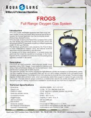
9PRODUCT OVERVIEWThis buoyancy jacket is specifically designed for military use with all types of back or chest worn breathingapparatus, including open circuit SCUBA, semi-closed circuit or closed circuit rebreathers.The <strong>MDB</strong> features a single air cylinder attachment that allows you to inflate the vest withcompressed breathing air. The air cylinder is equipped with a Groupe d' Etudes et de RecherchesSous-Marines (GERS M20) 90 degree connection for use on the jacket. Thebreathable inflator allows you to breathe from the bladder in an emergency situation.The distribution of the buoyancy chambers provides excellent safety performance, either duringbuoyant ascent (vertical stability) or at the surface (natural support position with head and shouldersout of the water). The bladder is constructed of heavy duty urethane coated 1000 denier blackmaterial which resists cuts, tears and abrasion and is impervious to sunlight and salt water. Twodrains with tethered caps on the bottom side makes draining fast and easy.The bag is sewn throughout with high strength nylon. A crotch harness with split strap design providesgreater comfort while maintaining ease of adjustment. In addition, it has two utility pocketson the left lobe.The <strong>MDB</strong> is suitable for all types of uses.SPECIAL FEATURES<strong>BC</strong> Air BreathingThe oral inflator is equipped with a breathing valve that allows the diver to breathe air from thebuoyancy compensator when inflated. This device is only to be used in case of an emergency.To breathe air from your <strong>BC</strong>, first slightly exhale through the oral inflator mouthpiece in order toremove excess water trapped in the mouthpiece’s body (Fig. 1). Then, inhale through the mouthpiece.This will activate the breathing valve and deliver air from the <strong>BC</strong>’s bladder. When doneinhaling, exhale through the mouthpiece. The breathing valve permits both inhaling and exhalingwithout any manipulation.Oral InflatorMouthpieceFig. 1PN 101239WARNING: Always keep in mind that breathing air from the <strong>BC</strong> also deflates the <strong>BC</strong>and changes your buoyancy. Always be prepared to add air in the <strong>BC</strong> from the emergencycylinder in order to get extra air to breathe and also extra buoyancy.Depending on the depth, the auxiliary cylinder will only provide a few minutes of air, so you must immediatelystart a controlled ascent to the surface.CAUTION: The inside of the bladder must be kept dry and clean of all contaminants.If not maintained properly, breathing from the <strong>BC</strong> in the case of an emergency couldcause suffocation or asphyxiation due to contamination.
113. Inspect the O-ring at the end of the fill adapter to make sure it is in good condition. Threadthe adapter onto the threaded outlet boss on the cylinder valve until finger tight (Fig. 3).CheckO-ringFig. 34. Loosen the yoke knob. While supporting the auxiliary cylinder in one hand, attach the adapterto a fully pressurized 200 BAR (2,900 PSI) scuba cylinder (Fig. 4).Relief Plug Yoke KnobFig. 45. Relief plug is fixed in the closed position on the GERS fill adapter when filling the auxiliarycylinder from a scuba cylinder.WARNING: DO NOT attempt to fill the auxiliary cylinder from a supply cylinder which containsmore than 200 BAR/ (2,900 PSI). Doing so may weaken and damage the cylinder.6. Open the handwheel on the auxiliary cylinder counterclockwise until the valve is completely open.7. VERY SLOWLY open the valve on the scuba cylinder.NOTE: Always fill the auxiliary cylinder as slowly as possible by turning the handwheel of thesupply valve slowly to control the rate of fill. Rapid filling will generate heat and will result inan incomplete fill after the cylinder cools. Make sure not to over-inflate or inflate too rapidly. Ifthe cylinder is warm to the touch afterward, the fill rate was too rapid.
12 <strong>MDB</strong> Technical Manual8. Close the valve of the supply cylinder and then the valve of the auxiliary cylinder. Slowly purgethe relief plug by depressing it down with your finger to relieve the high pressure air trapped inthe adapter.9. Loosen the yoke knob and remove the adapter from the supply cylinder. Unscrew the adapterfrom the auxiliary cylinder valve. Place the dust cap back in place and tighten the yoke knob.Attaching the Auxiliary Cylinder1. Before attaching the cylinder, inspect the o-ring located at the tip of the connector (Fig. 5).CheckO-ringFig. 52. Insert the cylinder into the retaining sleeve and align the threaded valve outlet with the cylinderconnector. Turn the knurled knob counterclockwise and thread the cylinder connector onto thevalve outlet until finger tight (Fig. 6).Fig. 6
13INFLATION METHODSUsing the Oral InflatorTo orally inflate your <strong>BC</strong> (Fig. 7), place your lips on the oral inflator mouthpiece (A) and exhale asmall amount of air into the mouthpiece to purge any water that may still be in the housing. Whilecontinuing to exhale into the mouthpiece, depress the oral inflator button (B) to inflate the <strong>BC</strong>.Immediately after exhaling, release the oral inflator button to prevent air from escaping.aFig. 7bUsing the Auxiliary Air CylinderTo inflate the <strong>BC</strong> using the auxiliary air cylinder, open the cylinder valve by turning the handwheelcounterclockwise. Close the cylinder valve when the bladder is adequately filled, otherwise, airwill escape from the over pressure relief valves.DEFLATION METHODSThroughout the course of a dive, it may be necessary to release air from the <strong>MDB</strong> using one ofthe two methods described in the following instructions. Each method uses a valve that is in a differentlocation. The method you choose at any time may depend on whether you are making yourinitial descent feet-first, head-first or maintaining neutral buoyancy underwater. Always rememberto utilize the valve that is at the highest point on the bladder (closest to the surface), dependingon your position in the water.Deflation via Oral InflatorTo deflate the <strong>MDB</strong> using the oral inflator, lift the inflator body to its highest possible position (abovethe head). Press the oral inflator button (See Fig. 7B) to start venting air. This method is most effectiveon the surface when starting the initial descent.NOTE: Depressing the oral inflator while the jacket is empty may cause water to enter theair bladder.
14 <strong>MDB</strong> Technical ManualDeflation via Dual Exhaust ValveInside the inflator’s corrugated hose is a nylon line that attaches the inflator to the dual valve atthe top of the airway assembly. You can vent air from the <strong>MDB</strong> by firmly pulling straight down onthe inflator. Once resistance is felt, only a pull of 7mm (.25 in) is required. The Rapid ExhaustValve (REV) provides an effective and convenient way to vent air from the <strong>BC</strong> while in either anupright or face down swimming position (Fig. 8). It also functions as an Over Pressure Relief Valve(OPRV) that will open automatically to relieve excessive air pressure. This feature is very criticalfor preventing stress or damage to the <strong>BC</strong>’s bladder (Fig. 9).Fig. 8Fig. 9CAUTION: The proper function of the overpressure relief valve is vital to preventdamage to the <strong>BC</strong> bladder. Unauthorized service or tampering may render thesevalves inoperable, and could cause the bladder to leak or burst. This type of damageis not repairable and is not covered under warranty.WARNING: Most training agencies recommend that you descend in an upright, feetfirstposition, in order to maintain a slower and more controlled descent. This is especiallytrue if you experience difficulty equalizing your ears or if you are descendingin low visibility conditions.
15DONNING & ADJUSTMENT PROCEDURESDonning1. One end of the crotch strap ( Fig. 10) has a singlemale quick-release buckle. The other end has twomale quick release buckles. Connect the single maleconnection to the female buckle located at the top ofthe <strong>MDB</strong> (A). Secure the excess webbing throughthe 3-bar slide (E).2. Ensure the rear lobe retaining strap male quickreleasebuckle is connected to the female quickreleasebuckle on the lower left lobe (B). Insert thefree end of the crotch strap through the sewn-in loopon the lobe retaining strap (C).3. Insert your arm through the straps as if youwere putting on a jacket. Reach back and hold theunconnected female buckle with one hand and insertthe male buckle with the other hand (D).BACEDFig. 104. Bring the free end of the crotch strap (Fig.11)between your legs and connect it to the two lowerfemale quick release-buckles at the front of the<strong>MDB</strong> (Fig 11A).AB5. Connect the female quick-release buckleto the male quick-release buckle at the front ofthe <strong>MDB</strong> just above where the crotch strap isattached (FIg 11B).Adjusting strap length1. The length of the straps may be adjusted byholding the strap and moving the 3-bar slide(Fig.10E) up or down the strap. After adjustingthe position of the 3-bar slide, readjust the strapthrough the quick release buckle.2. Once the straps are readjusted, don the <strong>MDB</strong> tomake sure the adjustments are correct.Fig. 11
16 <strong>MDB</strong> Technical ManualPRE-DIVE INSPECTIONWARNING: Before each use, the <strong>MDB</strong> must be given a thorough visual inspectionand functional test. NEVER dive with an <strong>MDB</strong> that shows signs of damage to itsbladder or valves until it has received a complete inspection and service from anauthorized repair technician.1. Orally inflate the <strong>MDB</strong> until the bladder is completely full. Manually pull down on the oral inflatorassembly to check the function of the REV, only a pull of 7mm (.25 in) is required once resistanceis felt (Fig. 12). Orally inflate the <strong>MDB</strong> again, squeeze the jacket until the OPRV opens to relieveexcess pressure (Fig. 13). Let go and verify it reseats and keeps the bladder fully inflated. Usecylinder air if required to activate OPRV.PULL DOWNON ORALINFLATORFig. 12 Fig. 132. Fully inflate the <strong>MDB</strong> once again and let it sit for 10 minutes to check for leaks and firmness(Fig. 14).WARNING: If you can hear any leaks or if the bladder begins to deflate within 10 minutes,DO NOT attempt to use the <strong>MDB</strong> until it has received service.Fig. 14
173. Inspect all quick release buckles (both male and female ends) that are attached at the top,sides and on the crotch strap of the <strong>MDB</strong> for cracks, breakage or general damage. Please referto the diagram in the donning and adjustment procedures section for specific quick release bucklelocations (Figs. 15-17).Fig.15 Fig. 16Fig. 174. Check stitching points on the cylinder retaining sleeve, quick release buckles, webbing, crotch& lobe retaining straps. Verify there is no excess wear to any of the sections of webbing on the<strong>MDB</strong> (Figs. 18-20).Fig. 18 Fig. 19Check stitching pointsFig. 20
18 <strong>MDB</strong> Technical Manual5. Verify all hook and loop material is not excessively worn and it is in good working condition (Fig. 21).Check Hook /Loop on PocketFig. 217. Check the dual valve connector, caps and cylinder connectors making sure they are sealedand no air is escaping (Figs. 22-24).Fig. 22 Fig. 23Fig. 246. Ensure that the auxiliary air cylinder has been completely filled to 200 BAR (2,900 PSI) (Fig. 25).Fig. 25
20 <strong>MDB</strong> Technical Manualc) Reinstall the drain caps, cylinder connectors and oral airway. Orally inflate the <strong>MDB</strong> until it ispartially inflated. Store the <strong>MDB</strong> partially inflated, away from direct sunlight and in a clean, dry area.Do not store in an enclosed space, such as a car trunk, where temperatures may fall below -18ºC(0ºF) or rise above 49ºC (120ºF).
21Note: Before performing any disassembly, refer to theexploded parts drawing which references all mandatoryreplacement parts. These parts should be replaced withnew and must not be reused under any circumstancesregardless of the age of the valve or how much use ithas received since it was last serviced.3. Pull back the hose (25) from the mouthpiece body (30). Pressthe pin (29) out from one side using a pin punch or similar tool torelease the braided nylon cord (24). Remove the hose (21) from thedual valve assembly, set the dual valve assembly to the side.CAUTION: Use only a plastic (pn 103102) or brass(pn 944022) o-ring removal tool when removing o-rings to prevent damage to the sealing surface.Even a small scratch across an o-ring sealing surfacecould result in leakage. Once an o-ring sealingsurface has been damaged, the part must bereplaced with new. DO NOT use a dental pick orany other steel instrument.ORAL INFLATORDisassemblyAirway MaintenanceProceduresAirway Disassembly1. Using the spanner wrench (pn 129198) to hold the push button(38), remove the nut (26) from the stem (34) with a 5.5mm nut driver.Use needle nose pliers to remove the washer (27) and the rubbervalve (28). Discard nut (26) and rubber valve (28).1. Turn the retaining collar and remove the dual valve assemblyfrom the connector. Remove the gasket (13) from the connector.2. Using a straight blade screwdriver, carefully lift out the fingers ofthe cage (39) and remove it from lower inflator housing (32).2. Using diagonal pliers (pn 9-45171), carefully remove the threeclamps (23) from the spiral hose (25) securing the inflator and dualvalve assemblies.CAUTION: Do not apply excessive force or pry againstthe housing/cage with the tip of the screwdriver.CAUTION: Do not cut the spiral hose while removingthe clamp.
22 <strong>MDB</strong> Technical Manual3. Remove the stem assembly and spring (33) through the front ofthe lower inflator housing (32). Remove the mouthpiece (31) fromthe mouthpiece body (30).Airway DisassemblyDUAL-VALVEDisassembly4. Using the spanner wrench (pn 129198), turn the push button (38)counterclockwise to loosen. It may be necessary to secure the stem(34) in a vise or a pair of soft jawed pliers to loosen the push button(38) as a small amount of Loctite 425 or 480 is used to secure thebutton. Ensure the stem is protected from damage.NOTE: The outer cap is bonded to the body of the dualvalve assembly with a non-permanent adhesive. It willbe necessary to separate this bond prior to performingfurther disassembly by carefully following the procedureoutline below.1. Locate the seam that runs along the circumference between thedual valve body (14) and the outer cap (18), where the cap is fastenedto the body. Using the plastic handle of a medium size screwdriveror similar lightweight blunt instrument, rap sharply against allpoints of the seam on the cap to break the adhesive bond.Seam5. Remove the push button (38), washer (37) and the inflatordiaphragm (36) from the stem (34). Next, remove the plastic valve(35) from the stem (30). It may be necessary to secure the stem ina vise or a pair of soft jawed pliers to remove the plastic valve asa small amount of Loctite 425 or 480 is used on the threads of thestem (30). Once removed, discard the push button (38), washer(37), inflator diaphragm (36) and plastic valve (35).CAUTION: Do not apply excessive force or use ahammer, mallet or other heavy instrument.2. While holding the dual valve assembly secure, firmly graspthe outer cap (18) and turn it counter-clockwise to loosen. Whilemaintaining slight inward pressure to counteract the spring pressureinside, continue turning the cap (18) until it has disengagedfrom the dual valve body (14). Remove the cap and the spring(17) beneath it. Closely examine the cap to check for any signs ofthread damage, distortion, cracking or chemical attack that mayindicate the use of excessive force or incorrect adhesive duringprevious service.6. Clean any residual Loctite from the large end of the stem (34).This Concludes Disassembly of the Oral InflatorBefore starting assembly, perform parts cleaningand lubrication in accordance with ProcedureA: Cleaning and Lubricating in the backof the manual.NOTE: If the cap cannot be turned, repeat step 1 tobreak the adhesive bond.
233. Remove the valve plate (16) with gasket (15) from the body (14)and remove the gasket from the valve plate. Discard the gasket andset the valve plate aside.NOTE: Before performing any assembly, it is importantto inspect all parts, both new and those that are beingreused, to ensure that every part and component is perfectlyclean and free of any dust, corrosion or blemishes.Before dressing each o-ring with Christo-Lube ® , check toensure it is clean, supple and free of any blemish.4. Locate the two holes on opposite sides of the barrel of the dualvalve body (14) which hold the arms of the poppet guide (22). Toremove the poppet guide and exhaust valve assembly from thedual valve body, press the arms of the poppet guide inward bysimultaneously inserting two small probes through the opposingholes in the barrel.WARNING: Use only genuine <strong>Aqua</strong> <strong>Lung</strong> ® parts subassembliesand components whenever assemblingany <strong>Aqua</strong> <strong>Lung</strong> ® product. DO NOT attempt to substitutean <strong>Aqua</strong> <strong>Lung</strong> ® part with another manufacturer’s,regardless of any similarity in shape, size or appearance.Doing so may render the product unsafeand could result in serious injury or death.Airway AssemblyORAL INFLATORAssembly5. When the arms of the poppet guide have disengaged from thebody, firmly grasp the braided nylon cord (24) and pull the exhaustvalve assembly straight out while holding the body secure. This willpull the poppet stem (20) out of the dump valve poppet (19). Removethe dump valve poppet and discard.1. Place the large end of the spring (33) into the lower inflatorhousing (32). Ensure the spring is oriented properly.6. Remove the braided nylon cord (24) from the poppet stem (20).Pull the poppet stem (20) and spring (21) straight out of the poppetguide (22).2. Place one small drop of Loctite 425 or 480 onto the base of thelarge diameter threads of the stem (34). Screw the plastic valve(35) onto the large diameter threads of the stem (34) until seatedhand tight. The taper of the plastic valve must face towards thecenter of the stem.Loctite425 or 480This Concludes Disassembly of the Dual ValveBefore starting assembly, perform parts cleaningand lubrication in accordance with ProcedureA: Cleaning and Lubricating in the backof the manual.
24 <strong>MDB</strong> Technical Manual3. Install the diaphragm (36) over the large threaded end of the stem(34) until it rests against the face of the plastic valve (35). Placethe washer (37) on top of the diaphragm (36) followed by one smalldrop of Loctite 425 or 480 onto the tip of the stem (large threads)and screw the button (38) onto the stem (34) until it bottoms outagainst the washer (37).6. Using needle nose pliers, place the rubber valve (28) flat end upover the small diameter threads of the stem (34). Install the washer(27) onto the small diameter thread end of the stem (34) so thatthe washer (27) is seated on top of the rubber valve (28). Place thelocknut (26) into a 5.5mm nut driver and engage the locknut ontothe stem assembly by turning clockwise.Loctite425 or 4804. Pass the stem assembly into the body, through the center of thespring (33). Ensure the stem assembly is centered properly.5. Set the cage (39) with the fingers facing out over the push button(38) of the assembly. Place the entire lower inflator assembly facedown on a clean surface against the cage (39). Secure the cage(39) to the lower inflator assembly by using an arbor press or gentlystriking with a rubber mallet. Check the assembly to ensure all ofthe fingers of the cage (39) are engaged in the internal groove ofthe lower inflator housing assembly.7. Insert the pin spanner (pn 129198) into the holes on the button.(38). Using the 5.5mm nut driver, turn the locknut (26) clockwiseuntil approximately 1/4 inch of the threads of the stem (34) areexposed opposite the locknut.8. Install mouthpiece (31) onto the mouthpiece body (30) with thecurved end facing out until the lower inflator housing seats into themouthpiece groove.CAUTION: Do not use excessive force while installingthe cage. Doing so could cause damage to the case orlower housing.This Concludes Assembly of the Oral Inflator.Please Refer to Final Assembly and Testing inthe back of the manual.
25Airway AssemblyDUAL-VALVEAssembly1. Dip the dump valve poppet (19) into soapy water and press securelyonto the barbed tip of the poppet stem (20). Slide the spring(21) onto the stem.3. Compress the poppet assembly with the forked end out ontothe poppet holding fixture. Using the inflator cord fixture, install thebraided nylon cord (24) through the hole in the poppet stem (20)and round the inflator cord post 2 times (Two loops around postand two passes through the stem). Tie a 2.5 cm (1 inch) loop onone end of the cord using a “Overhand Bow Knot”. Secure the cordby going through the open loop with the opposite cord end andtying three (3) “Half Hitches”. Trim the excess cord to 1/4 inch atboth knots and seal the cord ends using a propane lighter (fixturescan be locally manufactured).CAUTION: Do not damage the knots with the flame.2. Insert the poppet stem (20) through the flat end of the poppetguide (22).Distance between posts30.5 cm (12 inches)Overhand Bow Knot(3) Half Hitches4. Position the poppet guide assembly so that the larger rib facestoward the open side of the dual valve body (14), away from themanifold. Lubricate the dump valve poppet with a small amountof soapy water and align the arms of the poppet guide with thegrooves inside the barrel of the body. Insert the assembly into thebarrel only until the ears of the poppet guide rest above the rim.Large Rib
26 <strong>MDB</strong> Technical Manual5. Squeeze the arms of the poppet guide (22) so that the ears fitinside the barrel and press the poppet guide completely inwarduntil the ears snap into place inside their respective holes. Checkto ensure that the dump valve poppet (19) has passed through thetop of the barrel and remains properly seated over the end of thepoppet guide (22) inside the dual valve body (14).Airway Assembly1. Ensure the inside line of the bottom vent slot lines up with thecenter line of the dual valve body hose barb. Place the spiral hoseover the cord hook and compress it to expose the hook. Use thecord hook to pull the braided nylon cord through the spiral hose(small end of the hose).6. Install the gasket (15) onto the valve plate (16) and set the valveplate inside the dual valve body (14) with the gasket facing down.AlignHere2. Apply a small amount of Gasgacinch to the diameter of the dualvalve body (10), allow 15 seconds to get tacky. Slide the spiralhose (25) onto the dual valve body (14).GasgacinchHere7. Place the overpressure spring (17) directly in the center of thevalve plate (16), standing up.3. Lightly fasten a clamp (23) over the spiral hose (25) so that it isevenly seated near the end. Position the end of the clamp to eitherside and pull the end of the clamp sufficiently snug. Trim the excesslength with a pair of diagonal pliers (pn 9-45171).8. Carefully apply only one very small drop of Loctite brand, 425or 480 grade thread adhesive to the center thread of the outer cap(18). Position the cap directly over the spring and valve plate andpress down while turning clockwise to engage with the threads ofthe body. Continue turning clockwise by hand until snug.This Concludes Assembly of the Dual Valve.Please Refer to Final Assembly and Testing inthe back of the manual.
274. Insert retaining pin (29) half way into one hole of the mouthpiecebody (30). Capture both loop ends of the braided nylon cord (24)using your thumb and index finger facing up, slide the hose (25)back for clearance. Rotate your wrist pointing your thumb and indexfinger down to form a “Larks Head Knot” on both loop ends. Capturethe knot onto the pin (29) of the mouthpiece body.5. Press the pin (29) by hand until it engages equally into bothholes of the mouthpiece body (30). Apply a small amount of Gasgacinchto the diameter of the mouthpiece body hose barb. Allow15 seconds for the adhesive to get tacky and slide the hose ontothe mouthpiece body with the mouthpiece facing to the right handside of the user as worn.6. Secure each of the two clamps (23) to the spiral hose (25). Theoutside clamp head faces in line with the mouthpiece. Clamp edgedistance to the end of the hose is 3.18mm (1/8 inch). The otherclamp faces the opposite direction over the pin (29).Clamp 2Clamp 1This Concludes Assembly of the Airway.Please Refer to Final Assembly and Testing inthe back of the manual.
28 <strong>MDB</strong> Technical ManualNote: Before performing any disassembly, refer to theexploded parts drawing, which references all mandatoryreplacement parts. These parts should be replaced withnew and must not be reused under any circumstancesregardless of the age of the valve or how much use it hasreceived since it was last serviced.4. Remove the retaining ring (12) using reversible circlip pliers (pn111100) and discard the retaining ring. Remove the handwheel(11) and o-ring (8) from the connector (7). Discard o-ring (8).CAUTION: Use only a plastic (pn 103102) or brass (pn944022) o-ring removal tool when removing o-rings toprevent damage to the sealing surface. Even a smallscratch across an o-ring sealing surface could resultin leakage. Once an o-ring sealing surface has beendamaged, the part must be replaced with new. DO NOTuse a dental pick or any other steel instrument..90° Cylinder Valve ConnectorMaintenance ProceduresDisassembly5. Secure the connector (7) using soft jaw pliers. Use a 5mm hexkey adapter (pn 8367A23) and 3/8" flex handle drive (pn 9-44363)to turn the valve reducing connector (2) counterclockwise and removeit from the connector base (4). Remove the knurled nut (3)from the valve reducing connector (2) and set aside for reuse.1. Remove the cylinder connector (59) from the <strong>BC</strong> connector byunscrewing counterclockwise.Note: Loctite 414 superbonder is used to hold this part inplace in addition to the torque applied during assembly.2. Remove the gasket (13) and closely inspect it for damage, if damagedreplace the gasket. If any debris is found in the groove, use aclean cloth to remove. Examine the <strong>BC</strong> connector for any damage.6. Reinstall the valve reducing connector (2) into the connectorbase (4). Using soft jaw pliers, hold the connector (7) above theo-ring groove. Insert the 5mm hex key adapter (pn 8367A23) and3/8" flex handle drive into the valve reducing connector (2), so thatit is positioned horizontally and to the right. Turn the 3/8" flex handledrive counterclockwise to remove the connector base (4) fromthe connector (7). Unthread the valve reducing connector (2) fromthe connector base (4).3. Use the o-ring removal tool (pn 944022) to remove o-ring (1)from the valve reducing connector (2) and discard the o-ring.Note: Loctite 414 superbonder is used to hold this part inplace in addition to the torque applied during assembly.
297. Using a flat blade screwdriver, hold the sealing pin (10) in placeand unscrew the locknut (5) counterclockwise with a 5mm nutdriver, discard locknut. Remove the spring (5) from the sealing pin(9).NOTE: Before performing any assembly, it is importantto inspect all parts, both new and those that are beingreused, to ensure that every part and component is perfectlyclean and free of any dust, corrosion or blemishes.Before dressing each o-ring with Christo-Lube ® , check toensure it is clean, supple and free of any blemish.CAUTION: These components are under spring tension,use caution when removing.8. Remove the sealing pin (10) from the small end of the connector(7). Take the o-ring (9) off of the sealing pin (10), discard o-ring (9)and connector (7).AssemblyWARNING: Use only genuine <strong>Aqua</strong> <strong>Lung</strong> ® parts,sub-assemblies and components whenever assemblingany <strong>Aqua</strong> <strong>Lung</strong> ® product. DO NOT attempt tosubstitute an <strong>Aqua</strong> <strong>Lung</strong> ® part with another manufacturer’s,regardless of any similarity in shape, sizeor appearance. Doing so may render the product unsafeand could result in serious injury or death.90° Cylinder Valve ConnectorMaintenance Procedures1. Insert o-ring (9) onto sealing pin (10). Install the sealing pin (10)into the small end of the connector (7).9. Clean residual Loctite from the connector base (4) and valvereducing connector (2).Clean Residual LoctiteHere2. While holding the sealing pin (10) with a flat blade screwdriver,install the spring (6) onto the sealing pin (10), inside the connector(7). Place the locknut (5) into the 5mm nut driver and screw thelocknut (5) clockwise onto the sealing pin (10) until it is flush withthe end of the pin threads.HereHereThis Concludes Disassembly of the 90° CylinderValve ConnectorBefore starting assembly, perform parts cleaningand lubricating in accordance with ProcedureA: Cleaning and Lubricating in the backof the manual.
30 <strong>MDB</strong> Technical Manual3. Place one small drop of Loctite 414 Superbonder on the bottomthreads of connector base (4). Place the threaded opening of theconnector base (4) over the threaded end of the connector (7). Screwthe connector base (4) into the connector (7) handtight. Temporarilyinstall the valve reducing connector (2) into the connector base (4).Hold the connector (7) with soft jaw pliers. Insert the 5m hex keyadapter (pn 8367A23) and 3/8" flex handle drive (pn 9-44363) intothe valve reducing connector (2), so that it is positioned horizontallyand to the right. Tighten the connector base (4) into the connector(7) clockwise until handtight, then an additional 1/4 turn. Remove thevalve reducing connector (2) from the connector base (4).5. Install a new lubricated o-ring (8) onto the connector (7). Place thehandwheel (11) on the connector (7) and secure in place with a newretaining ring (12) using the reversible circlip pliers (pn 111100).NOTE: Ensure the retaining ring is properly orientedwhen installing (flat side up) back onto the connector.(1) Drop ofLoctite 414 SuperbonderCAUTION: Do not cross thread or overtighten theconnector base into the connector, this can causeirreversible damage to components.This Concludes Assembly of the 90° CylinderValve ConnectorPlease Refer to Final Assembly and Testing inthe back of the manual.4. Insert a new lubricated o-ring (1) onto the end of the valve reducingconnector (2) opposite the threads. Install the threaded end ofthe valve reducing connector (2) through the threaded end of theknurled nut (3). Place one small drop of Loctite 414 superbonderon the bottom threads of the valve reducing connector (2). Placethe threaded opening of the valve reducing connector (2) over thethreaded end of the connector base (4). Hold the connector (7)with soft jaw pliers. Using the 5mm hex key adapter (pn 8367A23)and 3/8" flex handle drive, tighten the valve reducing connector (2)clockwise into the connector base (4).(1) Drop ofLoctite 414 SuperbonderCAUTION: Do not cross thread or overtighten theconnector base into the connector, this can causeirreversible damage to components.NOTE: Excessive Loctite may cause the knurled nut tostick to the connector base or valve reducing connector.Rotate the knurled nut to free.CAUTION: Protective eyeware must be worn during installationof valve reducing connector into the connector.
31CYLINDER VALVE MAINTENANCEPROCEDURES3. Using the modified screwdriver (pn 941586), remove the handwheelnut (42), spring (43), handwheel (44) and washer (45) fromthe spindle (50).Note: Before performing any disassembly, refer to theexploded parts drawing, which references all mandatoryreplacement parts. These parts should be replacedwith new and must not be reused under any circumstances- regardless of the age of the valve or howmuch use it has received since it was last serviced.CAUTION: Use only a plastic (pn 103102) or brass(pn 944022) o-ring removal tool when removing o-rings to prevent damage to the sealing surface.Even a small scratch across an o-ring sealing surfacecould result in leakage. Once an o-ring sealingsurface has been damaged, the part must bereplaced with new. DO NOT use a dental pick orany other steel instrument.4. Remove the handwheel (44) and washer (45) from the spindle (50).Valve Disassembly1. Open cylinder valve counterclockwise and ensure cylinder (57)is fully depressurized. Secure cylinder in cylinder vise (pn 100397)and remove the cylinder valve from the cylinder by turning valvebody (55) counterclockwise with a 27mm (1-1/16 inch) crowfoot (pnFC34A) and 3/8" flex handle drive (pn 9-44363). When done, removecylinder from cylinder vise.5. Unscrew the valve seat adapter (53) from the body (55) usinga 3/8" flex handle drive (pn 9-44363) and 5mm hex key adapter(pn 8367A23).CAUTION: Loctite 242 is used to hold this part in placein addition to the torque applied during assembly.Note: If the valve seat adapter does not loosen, usea heat gun to heat up the body and adapter to loosenthe adhesive.CAUTION: Do not damage the internal surface ofthe valve seat adapter.2. Remove the o-ring (56) from the valve body (55). Use the appropriateo-ring tool (pn 944022). Discard o-ring.6. Remove the o-ring (54) from the valve seat adapter (53) anddiscard it.
32 <strong>MDB</strong> Technical Manual7. Holding the valve body assembly in a vise, use a 22mm (7/8inch) socket (pn 769354) and 3/8" flex handle drive (pn 9-44363) toremove the valve plug (46) from the body (55).This Concludes Disassembly of the Cylinder Valve.Before starting assembly, perform parts cleaningand lubrication in accordance with ProcedureA: Cleaning and Lubricating in the backof the manual.8. Remove the o-ring (47) from the valve plug (46) using the appropriateo-ring tool (pn 944022). Discard o-ring.9. Unscrew the valve seat (52) from the body (55) using the spindle(50) and oldham (51). Remove the oldham (51) and valve seat(52), discard the valve seat.10. Using your fingers, remove the washer (48) from the spindle (50).Take the brass o-ring tool (pn 944022) and remove the o-ring (49)from the groove in the spindle (50). Discard the o-ring and washer.Note: If the washer (48) does not come out on the spindle(50), check for it inside the valve plug (46).
34 <strong>MDB</strong> Technical Manual6. Apply a small amount of lubrication to the o-ring (54) and fit ontothe valve seat adapter (53). Apply one drop of Loctite 242 to thesmall threads and screw the valve seat adapter (53) into the body(55) hand tight. Using a Newton Meter torque wrench along witha 5mm hex key adapter (pn 8367A23), apply 10 Nm (89 in.lbs) oftorque to the valve seat adapter (53).FINAL ASSEMBLY AND TESTINGWARNING: Protective eyewear must be worn at alltimes during testing.1. Lay the gasket (13) flat inside the connector and mate the retainingcollar of the dual valve body (14) directly over it, onto the manifold.Gently turn the collar clockwise to engage the threads, being carefulto avoid cross threading and hold the airway in the desired positionwhile tightening the retaining collar by hand until snug.Loctite 242 hereNOTE: Ensure the dual valve body (14) sealing surfaceis properly aligned with the connector on the <strong>BC</strong> This isessential to achieve a proper seal.CAUTION: Do not lubricate threads of the valveseat adapter.7. Lubricate o-ring (56) and place it onto the body over the threadsand up on the shoulder. Lightly lubricate the threads of the body(55). Install cylinder (57) into cylinder vise (pn 100397) and screwthe body into the cylinder (57) until hand tight. Using a 27mm (1-1/16 inch) crowfoot (pn FC34A) and Newton Meter torque wrench,tighten valve assembly into cylinder to 30 Nm (22 ft.lbs).2. Lay the gasket (13) flat inside the connector and mate the retainingcollar of the 90° cylinder connector (59) directly over it, onto themanifold. Gently turn the collar clockwise to engage the threads,being careful to avoid cross threading and hold the 90° cylinderconnector in the desired position while tightening the retaining collarby hand until snug.This Concludes Assembly of the Cylinder ValveCylinder Valve Testing Procedure1. Fill cylinder to 34 BAR (500 PSI) and listen for audible leaks.Submerge in a fresh water supply and visually inspect valve for anyleaks that may be preset. If no leaks are detected, fill cylinder to200 BAR (2,900 PSI), again listen for audible leaks and submergein fresh water. If any leaks are detected, disassemble valve, replaceworn parts, rebuild and retest.CAUTION: Do not use tool to tighten the retaining collaronto the <strong>BC</strong> connector. Doing so may result in overtightening and /or cross threading and could causepermanent damage that will require replacement ofthe <strong>BC</strong> bladder.
353. While holding the dual valve assembly secure, firmly grasp theinflator assembly and pull it in a straight line directly away fromthe dual valve assembly. Check the attachment points of the spiralhose at both the dual valve assembly and the inflator assembly. Ifany signs of damage or decay can be detected, it is important toreplace the spiral hose before proceeding any further.6. Manually inflate the <strong>BC</strong> until it is taut and fully inflated. Press thepush button (38) and then pull down on the oral inflator to ensurea rapid and unobstructed exhaust using both methods of deflation.Fully inflate the <strong>BC</strong> once again and to listen closely for any signsof leakage.Push to DeflateNOTE: Ensure that cylinder connectors, dual valve/oralairway assembly and caps are secured to the <strong>BC</strong> prior tosubmerging. Failure to do so will cause water to enter theinternal bladder.Pull Down OnOral Inflator ToDeflate4. Immerse the inflator and surrounding area of the spiral hose infresh water to wet the lower portion of the airway assembly. Graspthe spiral hose approximately six inches above the inflator assemblyand pull the hose in a straight line away from the inflator withmoderate force while holding the inflator secure. Check to ensurethat no separation occurs at the attachment point and the hoseremains seated flush against the base of the inflator housing.7. Connect the cylinder to the 90° cylinder connector, turn thecylinder valve on to inflate the bladder until the overpressure reliefvalve (OPRV) releases the excess air from the bladder. Turn offcylinder and remove the cylinder from the <strong>BC</strong>. Check both caps(61), airway (58) and cylinder connector (59) for any signs ofleakage. If no leakage is detected, let bladder stand inflated forone hour. Check the firmness of the bladder after one hour haspassed. If the bladder has remained firm, no air loss has occurred.If the bladder has lost air, recheck all connections, inflate <strong>BC</strong>, submergeand check for leaks. If a continuous leak is detected, thecomponent must be disassembled and examined for damage orcontamination of the seals and seating surfaces.5. Finally, bend the spiral hose at a right angle. If the spiral hoseshows any sign of separating from the inflator assembly it is importantto replace the clamp.NOTE: If leakage is not immediately detected, allow the <strong>BC</strong>to stand for at least one hour to ensure that none exists.This Concludes The Testing Procedures ForThe Airway
36 <strong>MDB</strong> Technical Manual<strong>BC</strong> Patch Kit InstructionsWARNING: Do not attempt to perform these proceduresusing patches or adhesive other than thoseprovided in the <strong>BC</strong> Patch Kit pn 42611.3. Apply a generous coat of Weld-On 4784® adhesive to the materialof the <strong>BC</strong> surrounding the hole or tear. Allow this preliminarycoat to set for at least twenty four hours.WARNING: Do not attempt to patch a tear or puncturewhich is located directly over an internal baffle, within50mm (2 inches) of a seam or is larger than 13mm (1/2inch) in diameter or length.WARNING: Adhesive should only be applied in aroom with plenty of cross ventilation. Carefully readall cautions on the label of the adhesive and avoidinhaling vapors.<strong>BC</strong> Patch KitCAUTION: It is important to prevent any adhesion betweenthe internal surfaces of the bladder caused bythe entrance of adhesive through the hole or tear. Positionthe bladder as needed to maintain a separation ofthe bladder at the point of the hole or tear.4. After twenty four hours have elapsed, apply a generous secondcoat of adhesive to the material of the <strong>BC</strong> surrounding the holeor tear and to the glossy surface only of the patch. Wait exactlytwenty minutes.Glossy SideNon-Glossy Side1. Inspect the material of the <strong>BC</strong> surrounding the hole or tear toensure that it is perfectly clean and dry. Rinse and dry the <strong>BC</strong> toclean if necessary.5. After twenty minutes have elapsed, apply a third coat of adhesiveto the <strong>BC</strong> material, a second coat to the patch. Wait betweenfive to ten minutes for this coat to grow tacky and immediately applythe patch over the hole or tear, using a small roller to press outany pockets of air that may be present between the patch and <strong>BC</strong>material. Position a 2.27 kg (5 Lb.) weight directly over the patch toapply pressure and allow exactly one hour for the patch to set.2. Check to ensure that the patch extends at least twice the diameteror length of the hole or tear on all sides.NOTE: DO NOT allow the patch to set more than onehour before performing the next step.6. Partially inflate the <strong>BC</strong> no more than 1/2 full, causing the innersurface of the bladder to separate if adhesion has occurred. Applya final coat of adhesive over the entire patch area. Allow twentyfour hours to completely cure, an then fully inflate the <strong>BC</strong> to ensurethat leakage is no longer present. If the <strong>BC</strong> does not remaincompletely full for at least one hour, immerse it in fresh water todetermine the source of leakage and repair as needed.This Concludes <strong>BC</strong> Patch Kit Instructions
37Table 1: LIST OF TOOLSPART # DESCRIPTION APPLICATION129198 Adjustable FaceSpannerRemoval/Installation of Oral Inflator Push Button (38)101215 Tank FillAdapterCharging cylinder944022103102820466(2 oz.)O-ring Tool Kit(Brass)O-ring Tool(Plastic, 5 pk)Christo-LubeMCG 111Removal/Installation of O-ringsLubrication of O-rings/Parts820467(16 oz.)9-44363 Flex HandleDrive 3/8”Removal/Installation of Valve/Connector Parts111100 Circlip Pliers Removal/Installation of Circlip (12) on 90 Degree Connector100398 Vise Jaw Inserts for Cylinder( For Existing Shop Vise)Removal/Installation of Cylinder Valve100397 Table MountCylinder ViseSecures Cylinder (57) for Removal/Installation of CylinderValve9-45171 Diagonal Pliers(small)Removal/Installation of Clamps (23 & 41)941586 ModifiedScrewdriver(short)Removal/Installation of Handwheel Nut (42)8367A23 5mm Hex Key Adapter Removal/Installation of Valve Seat Adapter (53) and ValveReducing Connector (2)769354 22mm (7/8 inch)SocketRemoval/Installation of Valve Plug (46)
38 <strong>MDB</strong> Technical ManualTable 1: LIST OF TOOLS (continued)PART # DESCRIPTION APPLICATIONFC34A 27mm (1-1/16 inch) Crowfoot Removal/Installation of Valve Body (55)N/ACord Hook(Locally Manufactured)Installing Braided Nylon Cord (24) through Spiral Hose (25)N/APoppet Fixture(Locally Manufactured)Removal/Installation of Braided Nylon Cord (24)N/ACord Fixture(Locally Manufactured)Knot Tying Fixture for Braided Nylon Cord (24)N/A5.5mm Nut Driver5mm Nut DriverRemoval/Installation of Oral Inflator Locknut (26)Removal/installation of the Cylinder Connector Sealing PinNut (5)N/A Small Punch Removal/Installation of Poppet Guide (22) and Oral InflatorPin (29)N/A Pliers Removal/Installation of Oral Inflator Stem (34)N/AN/A3/8 Drive TorqueWrench; 0-15 Nm(0-132 in.lbs)Range3/8 Drive TorqueWrench; 0-110 Nm(0-81 ft.lbs)RangeTorquing of PartsTorquing of PartsN/A Screw Driver Removal/ Installation of Dual Valve Cap (18), ConnectorSealing Pin (10)N/A Soft Jaw Pliers Removal/Installation to Secure Connector (7)N/ANeedle NosePliersRemoval/Installation of Inflator parts
39Table 2: Torque SpecificationsPART # DESCRIPTION / KEY ITEM # TORQUE840923 Plug, valve (46) 15 Nm (133 in.lbs)840917 Body, valve (55) 30 Nm (22 ft.lbs)840919 Adapter, valve seat (53) 10 Nm (89 in.lbs)Table 3: Recommended Cleaners and LubricantsLUBRICANT/CLEANER APPLICATION SOURCEChristo-Lube MCG 111All o-rings<strong>Aqua</strong> <strong>Lung</strong>, PN 820466 orLubrication Technologies310 Morton StreetJackson, OH 45640(800) 477-8704CAUTION: Silicone rubber requires no lubrication or preservative treatment. DONOT apply grease or spray to silicone rubber parts. Doing so may cause a chemicalbreakdown and premature deterioration of the material.Oakite #31Acid bath for reusable stainless steel andbrass parts.Oakite Products, Inc.50 Valley RoadBerkeley Heights, NJ 07922CAUTION: Do not use muriatic acid for the cleaning of any parts. Even if stronglydiluted, muriatic acid can harm chrome plating and may leave a residue that isharmful to o-ring seals and other parts.White distilled vinegarNon-ionic Liquid dishwashingdetergent (diluted with warm water)Acid bath for reusable stainless steeland brass parts.Degreaser for brass and stainless steelparts; general cleaning solution for plasticand rubber.“Household” grade“Household” grade
40 <strong>MDB</strong> Technical ManualProcedure A: Cleaning and LubricatingCleaning Brass and Stainless Steel Parts1. Preclean in warm, soapy water* using a nylon bristle tooth brush.2. Thoroughly clean parts in an ultrasonic cleaner filled with soapy water. If there are stubborn deposits,household white distilled vinegar (acetic acid) in an ultrasonic cleaner will work well. DO NOTplace plastic, rubber or silicone parts in vinegar.3. Remove parts from the ultrasonic cleaner and rinse with fresh water. If tap water is extremely“hard,” place the parts in a bath of distilled water to prevent any mineral residue. Agitate lightly, andallow to soak for 5-10 minutes. Remove and blow dry with low pressure 1.7 BAR (25 PSI) filtered air.Inspect closely to ensure proper cleaning and like-new condition.Cleaning Plastic & Rubber PartsParts made of plastic or rubber may be soaked and cleaned in a solution of warm water mixed withmild dish soap. Use only a soft nylon toothbrush to scrub away any deposits. Rinse in fresh water andthoroughly blow dry, using low pressure filtered air.CAUTION: Do not place plastic and rubber parts in acid solutions. Doing somay alter the physical properties of the component, causing it to prematurelydegrade and/or break.Cleaning Hoses1. Hose fittings: Ultrasonically clean with soapy water*; vinegar is OK on tough corrosion (only hose ends).2. Run soapy water through hose if needed.3. Thoroughly rinse with fresh water (hang with hose ends down).4. Blow out hose before installing.Lubrication and DressingAll o-rings should be lubricated with Christo-Lube ® MCG 111. Dress the o-rings with a very light film ofgrease, and remove any visible excess by running the o-ring between thumb and forefinger. Avoid applyingexcessive amounts of Christo-Lube grease, as this will attract particulate matter that may causedamage to the o-ring.*Soapy water is defined as “household” grade liquid dishwashing detergent diluted in warm water.
41EXPLODED PARTS DIAGRAMS840558 Connector Assy, Bouee PolyvalenteKey # PN PN* Description Qty1 820038P 124704 O-ring (20 pk) 12 101028 N/A Connector, valve reducing,non-mag 13 101029 N/A Nut, knurled 14 840562 N/A Connector, base, non-mag 15 101335 N/A Locknut, 5mm 16 101332 840443 Spring 17 101334 850442 Connector 18 820089 N/A O-ring 19 820005 N/A O-ring 110 101328 N/A Pin, sealing, non-mag 111 101341 862476 Collar, swivel 112 101344 850443Retaining ring, non-mag15.7mm1*<strong>Aqua</strong> <strong>Lung</strong> France Part NumbersLoctite 414 Superbonder12 313 14Loctite 414Superbonder4567891024201921221523Loctite425 or 48016171811251241101239 Airway Complete4023Key # PN PN* Description Qty13 15309 N/A Gasket, connector seal 414 42742 N/A Dual valve body assembly, ACME 115 15714 N/A Gasket, REOP 116 15698 N/A Plate, valve 117 15643 N/A Spring, over pressure, non-mag 118 15707 N/A Cap, REOP 119 778559 N/A Poppet, dump valve 120 778556 N/A Stem, poppet, non-mag 121 15644 N/A Spring, pull dump, non-mag 122 15649 N/A Guide, poppet 123 15719 N/A Clamp, black, plastic tie 324 17523 N/A Cord, braided nylon (1 in) 56 in25 15149 N/A Hose, spiral 11.5 in 126 101267 116622 Locknut, non-mag 127 101247 N/A Washer, non mag 128 101226 840493 Valve, rubber 129 15645 N/A Pin, retaining, non-mag 130 101227 840211 Body, mouthpiece 131 101237 840477 Mouthpiece 132 101231 840482 Housing, lower inflator 133 101246 840490 Spring, non-mag 134 101248 N/A Stem, non-mag 135 101232 840486 Valve, plastic 136 101233 840487 Diaphragm, inflator MP 137 101234 840488 Washer 138 101222 840489 Push button 139 101236 840496 Cage 1Not included in the assembly40 762979 841106 Whistle, ball type 141 104913 N/A Clamp, strap black 1312930262728343335383637Loctite 414 Superbonder32Loctite 425 or 480*<strong>Aqua</strong> <strong>Lung</strong> France Part Numbers39
42 <strong>MDB</strong> Technical ManualEXPLODED PARTS DIAGRAMS15 Nm4243444546474849505152840970 .43L Cylinder w/Valve (export)Key # PN* Description Qty42 840922 Nut, handwheel 143 228121 Spring 144 228176 Handwheel 145 213421 Washer 146 840923 Plug, valve 147 850218 O-ring 148 840523 Washer 149 840163 O-ring 150 840921 Spindle 151 840199 Oldham 152 228365 Seat, valve 153 840919 Adapter, valve seat 154 850219 O-ring 155 840917 Body 156 850228 O-ring 157 840955 Cylinder .43L 220 BAR, black, alu 1*<strong>Aqua</strong> <strong>Lung</strong> France Part Numbers10 NmLoctite 2425530 Nm53545657
43<strong>MDB</strong> COMPONENTSFRONT581359136062a63BACK62b61 131361<strong>MDB</strong> Parts ListKey # PN Description Qty13 15309 Gasket, Connector seal 458 101239 Airway Complete, Atlantis, Non-mag 159 840558 Connector, Assy, Bouee Polyvalente 160 841335 Vest Only , <strong>MDB</strong>, Packaged 161 15665 Cap, Universal Connector 262a 762956 Removable Chest Strap, 1.0", Atlantis 162b 762957 Kit, Waist Strap, 1.5", Atlantis 163 840970 Cylinder, .43L w/ Valve (Export) 1
44 <strong>MDB</strong> Technical ManualOVERHAUL PARTS KITS840556 Kit, Cylinder ConnectorKey # PN PN* Description Qty1 820038 124704 O-ring 15 101335 840444 Locknut, 5mm 17 101334 850442 Connector 18 820089 718305 O-ring 19 820005 111336 O-ring 112 101344 850443 Retaining ring, non-mag 15.7mm 1101240 Kit, Oral Inflator, AtlantisKey # PN PN* Description Qty15 15714 N/A Gasket, REOP 119 778559 N/A Poppet, dump valve 123 15719 N/A Clamp, black, plastic tie 326 101267 116622 Locknut, non-mag 128 101226 840493 Valve, rubber 135 101232 840486 Valve, plastic 136 101233 840487 Diaphragm, inflator MP 137 101234 840488 Washer 138 101222 840489 Push button 1840971 Kit, Cylinder (Export)Key # PN* Description Qty47 850218 O-ring 148 840523 Washer 149 840163 O-ring 152 228365 Seat, valve 154 850219 O-ring 156 850228 O-ring 1*<strong>Aqua</strong> <strong>Lung</strong> France Part NumbersKey # PN PN* Description QtyN/A 42611 N/A Bladder Repair Kit 1*<strong>Aqua</strong> <strong>Lung</strong> France Part Numbers
45<strong>TECHNICAL</strong> DATAAnnual MaintenanceThe <strong>MDB</strong> is subject to annual maintenance. All parts listed in the overhaul parts kit must bereplaced annually, even if they appear to be in good condition.Composition•••••1 Vest only (Key #60) is constructed of heavy duty urethane coated 1000 denier black material.1 Airway complete (Key #58).1 90° Cylinder connector (GERS connection) (Key #59).2 Caps (located rear inside lobes Key #61).1 Auxiliary air cylinder, with valve (GERS connection) (Key # 63).Features• 1 Rapid exhaust valve (REV) is operated by an easily accessible cord, also acts as an over pressurerelief valve (OPRV). (Located top of the airway complete Key #58).(** Refer to <strong>MDB</strong> Components for specific locations)LIFT CAPACITY (Fresh Water) .........14L (33 lbs)CYLINDER CAPACITY ...............1 X .43LCYLINDER WORKING PRESSURE ....200 BAR (2,900 PSI)DUAL VALVE OPENING PRESSURE (non-mag) .09 - .16 BAR (1.3 - 2.3 PSI)OVER PRESSURE RELIEF VALVE OPENING PRESSURE (OPRV) (non-mag) .07 - .14 BAR (1 - 2 PSI)DUAL VALVE & OVER PRESSURE RELIEF VALVE (OPRV) CLOSING PRESSURE IS .07BAR (1 PSI) UNDER OPENING PRESSUREWEIGHT (with cylinder) .............3.0 kg (6.61 lbs)(without cylinder) ...........1.8 kg (3.9 lbs)PACKING (individual box) .............62.2 cm X 41 cm X 11.4 cm(24.5” X 16” X 4.5”)TOTAL PACKED WEIGHT. ............3.7 kg (8.1 lbs)References841345: <strong>MDB</strong> W/O cylinderAccessories:840970........0.43 L cylinder with valve (GERS connection)15665..........Cap, universal connector (for use without cylinder)15309..........Gasket, connector seal840817........ Adapter, tank fill, GERS
46 <strong>MDB</strong> Technical ManualMaintenance Notes
47WARRANTY INFORMATIONAll warranty transactions must be accompanied by proof of original purchase from an <strong>Aqua</strong> <strong>Lung</strong> ® authorizeddealer/agent. Be sure to save your sales receipt, and present it whenever returning your <strong>MDB</strong>for warranty service.The <strong>Aqua</strong> <strong>Lung</strong> ® One Year Limited Warranty <strong>Aqua</strong> <strong>Lung</strong> America warrants to the original purchaser for a period of one year from the date of purchasethat the product will be free from defects in material and workmanship; provided that it receives normaluse, proper care, and prescribed dealer service subject to those restrictions stated below. This limitedwarranty is extended only to the original purchaser for purchases made from an authorized <strong>Aqua</strong> <strong>Lung</strong> ®dealer, and is not transferable. This warranty is limited to repair or replacement only at the discretion of<strong>Aqua</strong> <strong>Lung</strong> America, Inc.ALL WARRANTIES, INCLUDING, BUT NOT LIMITED TO, IMPLIED WARRANTIES, ORMERCHANTABILITY AND FITNESS FOR A PARTICULAR PURPOSE ARE LIMITED INDURATION TO A PERIOD ENDING ONE YEAR FROM THE DATE OF PURCHASE.AQUA LUNG AMERICA DISCLAIMS AND EXCLUDES ANY LIABILITY FOR INCIDENTAL,OR CONSEQUENTIAL DAMAGES. SOME STATES DO NOT ALLOW EXCLUSIONS OFLIABILITY, SO THIS MAY NOT APPLY TO YOU.WARNING: It is dangerous for untrained and uncertified persons to usethe equipment covered by this warranty. Therefore, use of these productsby an untrained person renders any and all warranties null andvoid. Use of SCUBA equipment by anyone who is not a certified diver, orreceiving training through a recognized certification agency, shall rendervoid all warranties, expressed or implied.RestrictionsThe following restrictions apply to this warranty:• This warranty extends to inflator parts, and to the seams of the <strong>BC</strong> bladder. Factory prescribedannual service by a trained technician is required.• This warranty does not extend to abrasion, punctures, or tears of the bladder, or seam separationcaused by chemical attack; including prolonged exposure to chlorine.• This warranty does not extend to damages caused by improper use, impropermaintenance, neglect, unauthorized repairs, modifications, accidents, fire, or casualty.• Cosmetic damage, such as scratches, fraying, and nicks are not covered by this warranty.• This warranty covers products purchased in the United States. For warranties that may applyelsewhere, please contact your local representative.• Failure to meet any of the above requirements will render the warranty null and void.
<strong>MDB</strong><strong>Military</strong> <strong>BC</strong>2340 Cousteau Court • Vista, CA 92081Phone (760) 597-5000 • Fax (760) 597-4900www.aqualung.com/militaryandprofessional©2011 <strong>Aqua</strong> <strong>Lung</strong> InternationalLiterature PN 18205 Rev. 10/11