00-02-0660; revision date â 06/2010 - Murphy
00-02-0660; revision date â 06/2010 - Murphy
00-02-0660; revision date â 06/2010 - Murphy
- No tags were found...

Create successful ePaper yourself
Turn your PDF publications into a flip-book with our unique Google optimized e-Paper software.
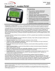
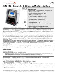
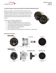
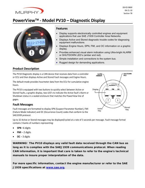
<strong>00</strong>‐<strong>02</strong>‐<strong>06</strong>6<strong>00</strong>6‐21‐10Section 78PowerView ‐ Model PV10 – Diagnostic DisplayProduct DescriptionFeatures• Display supports electronically controlled engines and equipmentapplications that use SAE J1939 Controller Area Networks.• Displays Active and Stored diagnostic trouble codes for diagnosingequipment malfunctions.• Displays Engine Hours, SPN, FMI, and OC information on a graphicdisplay.• Provides enhanced visual alarm indication using Ultra-bright ALARMor SHUTDOWN LED’s (amber and red).• Simple installation and connections to the system bus.• Rugged design for demanding applications.The PV10 Diagnostic display is a CAN device that receives data from a controlleror ECU and then displays Active and Stored Fault messages and Engine Hours.The default mode provides hourmeter data from the ECU for cumulative enginehours.The PV10 is equipped with two buttons to quickly select between Active orStored Faults, a graphic display, two LED's to indicate the Active fault's Alarm orShutdown status in a sealed enclosure that matches the PowerView line ofgages.Fault MessagesFault messages are formatted to display SPN (Suspect Parameter Number), FMI(Failure Mode Indicator) and OC (Occurrence Count) codes that conform to theSAEJ1939 protocol.Up to 32 Active or Stored messages may be displayed/cycled at a rate of 3 seconds per message. Fault message formatcontains 3 banks of numbers representing:• SPN –6 digits• FMI – 2 digits• OC – 3 digitsWARNING! The PV10 displays any valid fault data received through the CAN bus aslong as it is complies with the SAEJ1939 communications protocol. When readingCAN information, it is important that care is taken to refer to the engine’s technicalmanuals to insure proper interpretation of the data.For more specific information, contact the engine manufacturer or refer to the SAEJ1939 specifications at www.sae.org.
Display OperationUp to 32 diagnostic fault codes may be displayed for 3 second each. Whether in Active or Stored mode, pressing “!” or “i”respectively, will immediately advance to the next message. Holding down a key will quickly cycle through messages.Engine HoursBy default, the PV10 unit displays in hourmeter mode, indicated by a cursor above the wordHOURS. After viewing Active or Stored Faults, the screen will return to Engine Hours mode.PGN (Parameter Group Number) 65253, Engine Total Hours of OperationActive FaultsWhen the PV10 diagnostic display receives an Active Fault:• the LED Alarm will light• the cursor will indicate ‘Active’• all Active Fault code(s) will displayAfter scrolling through all the faults, the display returns to Engine Hours. After 3 secondsPV10 looks for the next Active Fault message and the process repeats.You may also display Active Faults at any time by pressing “!”.Stored FaultsPress “i” to display Stored Faults. Notice the cursor moves to the STORED indicator. Afterthe PV10 scrolls through all the Stored Faults, the device returns to Engine Hours.NOTE: If the LED Alarm lights up while displaying Stored Faults, you may press “!” toimmediately display the Active Faults. Otherwise, the PV10 will finish scrolling through theStored Fault codes, return to Engine Hours for 3 seconds, and then displays the Active Faults.Blank DisplayWhen all dashes are displayed in place of numbers, the PV10 received invalid or no data todisplay Engine Hours, Active or Stored Faults.Product Dimensions
Connection DetailTypical Wiring DiagramWARNING! READ NOTES below before installing the PV10.NoteUse resistor between CAN_H and CAN_L line near PowerView (included in some cables or factory purchased panels). Resistorcan be installed in the wire harness attached to Port A or a terminating resistor (<strong>Murphy</strong> P/N 78<strong>00</strong>480) can be attached to PortB. Do not connect a terminating resistor to Port A and B simultaneously. If PV10 is not the last device on the CAN bus, placeterminator resistor at last CAN device.Use SAE J1939 CAN compliant wiring.Only use 120 OHM characteristic impedance cable, ex. Belden 9841.CAN Shield connected to ECU end only.Do not connect to PV10 Port B other than to terminate CAN bus. See Note 1.Terminating resistor at ECU end of harness.WARNING: Two 120 Ohm resistors should be located at opposite ends of the J1939 CAN bus. Failure to comply will cause busfailures. Only two 120 Ohm resistors are allowed on the J1939 CAN bus. ECU terminating resistor is typically located in theharness, but can be located inside the ECU’s. For ECU resistor location check with OEM, equipment supplier, or ECUspecification.
SpecificationsOperating Voltage• 6.0 VDC minimum to 36 VDC maximumPower Supply Operating Current• 460mA max @ 12VDC• 810mA max @ 24VDCReversed Polarity: Withstands reversed battery terminal polarity.Environmental• Operating Temperature: -40°C to 70°C (-40°F to 158°F)• Storage Temperature: -55°C to 85°C (-67°F to 185°F)• Sealing: IP68CAN Bus: SAE J1939 compliantCase: Polycarbonate /PBT blendClamp: PBTConnectors:• 4-pin AMP “Mini-universal Mate-N-Lok“ connector• AMP Plug: P/N 172338-1• AMP Socket: P/N 171639-1 (4 each, assumes 18 gauge wire. See AMP Plug specificationto match socket and wire size.)Maximum Panel Thickness: 3/8 inch (9.6 mm)Shipping Weights (all models): 0.2 lb. (0.1 kg.)Shipping Dimensions (all models): 3‐7/8 x 2‐3/4 x 2‐3/4 in. (98.4 x 69.85 x 69.85 mm)AccessoriesWiring Harness, PVW‐PDA‐12 PowerView 10 CAN and Power (PN 78‐<strong>00</strong>‐<strong>06</strong>13)Wiring Harness, PA‐30 PowerView 10 Loose Wiring (PN 78‐<strong>00</strong>‐<strong>06</strong>14)Terminating Resistor, PVMJR (PN 78‐<strong>00</strong>‐0480)NOTE: For additional information on PV10 accessories and Quick Connect Diagram, visit ourwebsite: www.fwmurphy.com/pv10In order to consistently bring you the highest quality, full featured products, we reserve the right to change our specifications and designs at any time.MURPHY, the <strong>Murphy</strong> logo, <strong>Murphy</strong>Link and PowerView are registered and/or common law trademarks of <strong>Murphy</strong> Industries, Inc. This document,including textual matter and illustrations, is copyright protected by <strong>Murphy</strong> Industries, Inc., with all rights reserved. (c) <strong>2010</strong> <strong>Murphy</strong> Industries, Inc.