00-02-0660; revision date â 06/2010 - Murphy
00-02-0660; revision date â 06/2010 - Murphy
00-02-0660; revision date â 06/2010 - Murphy
- No tags were found...

Create successful ePaper yourself
Turn your PDF publications into a flip-book with our unique Google optimized e-Paper software.
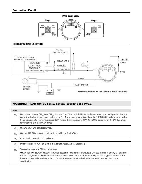
Connection DetailTypical Wiring DiagramWARNING! READ NOTES below before installing the PV10.NoteUse resistor between CAN_H and CAN_L line near PowerView (included in some cables or factory purchased panels). Resistorcan be installed in the wire harness attached to Port A or a terminating resistor (<strong>Murphy</strong> P/N 78<strong>00</strong>480) can be attached to PortB. Do not connect a terminating resistor to Port A and B simultaneously. If PV10 is not the last device on the CAN bus, placeterminator resistor at last CAN device.Use SAE J1939 CAN compliant wiring.Only use 120 OHM characteristic impedance cable, ex. Belden 9841.CAN Shield connected to ECU end only.Do not connect to PV10 Port B other than to terminate CAN bus. See Note 1.Terminating resistor at ECU end of harness.WARNING: Two 120 Ohm resistors should be located at opposite ends of the J1939 CAN bus. Failure to comply will cause busfailures. Only two 120 Ohm resistors are allowed on the J1939 CAN bus. ECU terminating resistor is typically located in theharness, but can be located inside the ECU’s. For ECU resistor location check with OEM, equipment supplier, or ECUspecification.