PowerFlex 4_40 with MicroLogix1100 on ModbusRTU_broadcast
PowerFlex 4_40 with MicroLogix1100 on ModbusRTU_broadcast
PowerFlex 4_40 with MicroLogix1100 on ModbusRTU_broadcast
You also want an ePaper? Increase the reach of your titles
YUMPU automatically turns print PDFs into web optimized ePapers that Google loves.
Overall Descripti<strong>on</strong><br />
<str<strong>on</strong>g>PowerFlex</str<strong>on</strong>g> 4 class drives can be c<strong>on</strong>trolled over Modbus RTU using the built-in serial interface (DSI<br />
c<strong>on</strong>nector) <strong>on</strong> the drive. This applicati<strong>on</strong> note details the Micrologix 1100 plc being used as Modbus<br />
RTU master to c<strong>on</strong>trol <str<strong>on</strong>g>PowerFlex</str<strong>on</strong>g> 4 class drives using <strong>broadcast</strong> c<strong>on</strong>trol.<br />
To c<strong>on</strong>trol a drive <strong>on</strong> Modbus RTU, each drive needs to use a seperate message (MSG) command for<br />
the Logic C<strong>on</strong>trol word, Speed Reference word, Logic Status word and Speed Feedback word. With a<br />
large number of drives <strong>on</strong> the network, it can take a significant period of time before the MSG instructi<strong>on</strong><br />
for the last drive to start, is executed. Modbus RTU supports a global <strong>broadcast</strong> feature, whereby <strong>on</strong>e<br />
MSG instructi<strong>on</strong> is used to write the same value to same register in every drive, by using the Modbus<br />
RTU command ‘16’ to the Modbus address ‘0’. This means that we could <strong>broadcast</strong> the Logic Command<br />
word to start /stop all the drives together, or provide a comm<strong>on</strong> speed reference to the drives. This could<br />
significantly reduce the time to c<strong>on</strong>trol a number of drives <strong>on</strong> the network.<br />
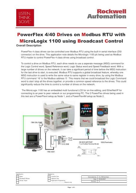
The MicroLogix 1100 has an embedded multi functi<strong>on</strong>al LCD for <strong>on</strong>-line editing, and EtherNet/IP for<br />
c<strong>on</strong>necting to an peer to peer network or our programming PC. The 2 <str<strong>on</strong>g>PowerFlex</str<strong>on</strong>g> drives being used in<br />
this test are a <str<strong>on</strong>g>PowerFlex</str<strong>on</strong>g>4 setup as Node 1, and a <str<strong>on</strong>g>PowerFlex</str<strong>on</strong>g>4M setup as Node 2.<br />
Distributi<strong>on</strong>: Related to:<br />
x Open x Inverter Use<br />
Rockwell Offices Opti<strong>on</strong>s Use<br />
Drives Team Applicati<strong>on</strong> Experience<br />
_________________(Name) <strong>on</strong>ly<br />
Page 1 of 6<br />
Generated by D.J.Withenshaw<br />
Date 05/09/2007<br />
Revisi<strong>on</strong> A<br />
!
Equipment used for test<br />
MicroLogix 1100 1763-L16AWA<br />
RSLogix500 CPR ver 7 and RSLinx ver 2.51<br />
The <str<strong>on</strong>g>PowerFlex</str<strong>on</strong>g> 4 class drives need a minimum firmware revis<strong>on</strong> to support Modbus RTU code ‘16’:<br />
<str<strong>on</strong>g>PowerFlex</str<strong>on</strong>g> 4 – frn 4.02<br />
<str<strong>on</strong>g>PowerFlex</str<strong>on</strong>g>4M – frn 1.01<br />
<str<strong>on</strong>g>PowerFlex</str<strong>on</strong>g><str<strong>on</strong>g>40</str<strong>on</strong>g> – frn 3.03<br />
<str<strong>on</strong>g>PowerFlex</str<strong>on</strong>g><str<strong>on</strong>g>40</str<strong>on</strong>g>P and <str<strong>on</strong>g>40</str<strong>on</strong>g>0 have not been tested<br />
1761-CBL-PM02 ser B, PC to MicroLogix programming cable<br />
1763-NC01 The phoenix plug pin c<strong>on</strong>nect<strong>on</strong>s are the same as the RS485 <strong>on</strong> the NET-AIC<br />
AK-U0-RJ45-TB2P 2 positi<strong>on</strong> terminal block<br />
Modbus RTU requires a 120 Ohm terminator at each end of the network. Putting a link between pins 1<br />
& 2 of the terminal block terminates <strong>on</strong>e end, and a 120 Ohm resistor is screwed into the 2 positi<strong>on</strong><br />
terminal block at the other end.<br />
Drive Parameter setup<br />
Drive parameters need to be setup as below. When para change complete, cycle the drive power.<br />
Parameter PF4,<br />
<str<strong>on</strong>g>40</str<strong>on</strong>g>, <str<strong>on</strong>g>40</str<strong>on</strong>g>P, <str<strong>on</strong>g>40</str<strong>on</strong>g>0<br />
Parameter PF4M Details Value<br />
P36 P106 Start source from Network 5<br />
P38 P108 Speed reference from network 5<br />
A103 C302 Comm data rate set at 19200kb 4<br />
A104 C303 Comm node address set to 1 1 & 2<br />
A107 C306 Comm format set to RTU 8-N-1 0<br />
MicroLogix Setup<br />
The MicroLogix 1100 needs to be setup first using the serial cable 1761-CBL-PM02 <strong>on</strong> channel 0.<br />
If when c<strong>on</strong>necting to the ML1100 an error is reported that it is not an SLC, then upgrade RSLogix to ver<br />
7 and RSLinx to ver 2.50.<br />
Startup RSLogix500 and create a new project <str<strong>on</strong>g>with</str<strong>on</strong>g> the Micrologix 1100<br />
Distributi<strong>on</strong>: Related to:<br />
x Open x Inverter Use<br />
Rockwell Offices Opti<strong>on</strong>s Use<br />
Drives Team Applicati<strong>on</strong> Experience<br />
_________________(Name) <strong>on</strong>ly<br />
Page 2 of 6<br />
Generated by D.J.Withenshaw<br />
Date 05/09/2007<br />
Revisi<strong>on</strong> A
Select channel c<strong>on</strong>figurati<strong>on</strong><br />
Setup Channel 1 EtherNet IP address and subnet. Make sure you uncheck the BootP enable, and then<br />
download to the c<strong>on</strong>troller.. To make the IP address stick, cycle the power <strong>on</strong> the ML1100.<br />
Now we have the IP address in the ML1100, then we can rec<strong>on</strong>figure our computer and go-line using<br />
the EtherNet c<strong>on</strong>necti<strong>on</strong>. This will allow us to remove the serial cable 1761-CBL-PM02 <strong>on</strong> channel 0,<br />
and use plug in the 1763-NC01 and rec<strong>on</strong>figure Channel 0 for Modbus RTU.<br />
Additi<strong>on</strong>ally ensure that the settings <str<strong>on</strong>g>with</str<strong>on</strong>g>in the ML1100 are setup <strong>on</strong> the LCD:<br />
ESC …. Scroll down ….. Advance Set …… DCOMM Cfg = disable<br />
Change to cable 1763-NC01, and select the channel c<strong>on</strong>figurati<strong>on</strong> as before.<br />
Setup channel 0 to be Modbus RTU master at 19200 <str<strong>on</strong>g>with</str<strong>on</strong>g> no parity<br />
Distributi<strong>on</strong>: Related to:<br />
x Open x Inverter Use<br />
Rockwell Offices Opti<strong>on</strong>s Use<br />
Drives Team Applicati<strong>on</strong> Experience<br />
_________________(Name) <strong>on</strong>ly<br />
Page 3 of 6<br />
Generated by D.J.Withenshaw<br />
Date 05/09/2007<br />
Revisi<strong>on</strong> A
Distributi<strong>on</strong>: Related to:<br />
x Open x Inverter Use<br />
Rockwell Offices Opti<strong>on</strong>s Use<br />
Drives Team Applicati<strong>on</strong> Experience<br />
_________________(Name) <strong>on</strong>ly<br />
Page 4 of 6<br />
Make sure you adjust the protocol c<strong>on</strong>trol<br />
from the default No handshaking to No<br />
handshaking (485 network) and the<br />
timeouts /delays to 20ms.<br />
Download c<strong>on</strong>figurati<strong>on</strong> to c<strong>on</strong>troller using<br />
the EtherNet c<strong>on</strong>necti<strong>on</strong>.<br />
Once the ML1100 is in run mode, both<br />
COMM0 and COMM1 will be flashing fast<br />
The ML1100 communicates <str<strong>on</strong>g>with</str<strong>on</strong>g> the drive using MSG instructi<strong>on</strong>s <strong>on</strong> Modbus RTU. So we create a<br />
number of MSG instructi<strong>on</strong>s for the Logic c<strong>on</strong>trol, reference , logic status and drive speed feedback..<br />
The MSG instructi<strong>on</strong>s are cascaded so that they all operate in sequence. This scheduling of MSG<br />
instructi<strong>on</strong>s is necessary to ensure that each instructi<strong>on</strong> receives its hand-shake and completes<br />
properly.<br />
Generated by D.J.Withenshaw<br />
Date 05/09/2007<br />
Revisi<strong>on</strong> A
The logic command data will be stored in N15:0, so c<strong>on</strong>figure the message to send N15:0 to the Modbus<br />
address for the logic command at 8192 (this means modbus sends to address 8193). Notice that we use<br />
the command ’16 Write Multiple Registers’, and the Slave node address is ‘0’.<br />
When the program is downloaded, we can go <strong>on</strong>line and change the logic word to start and stop the drive.<br />
Double click <strong>on</strong> the N15 data file, and change the value of N15:0 to 2. The drives will now start.<br />
Changing the value of N15:0 to 1 will stop the drives.<br />
The bits that are part of the Logic C<strong>on</strong>trol word are:<br />
Distributi<strong>on</strong>: Related to:<br />
x Open x Inverter Use<br />
Rockwell Offices Opti<strong>on</strong>s Use<br />
Drives Team Applicati<strong>on</strong> Experience<br />
_________________(Name) <strong>on</strong>ly<br />
Page 5 of 6<br />
Generated by D.J.Withenshaw<br />
Date 05/09/2007<br />
Revisi<strong>on</strong> A
The plc MSG 11:1 <strong>broadcast</strong>s the reference to all drives <strong>on</strong> address 8194 via N15:1. Therefore change<br />
the value of N15:1 between 0 to 500 = 50.0Hz.<br />
The <strong>broadcast</strong> message is a write MSG to all the drives <strong>on</strong> the network, typically used for the Logic<br />
C<strong>on</strong>trol and reference words. Other drive registers would be read <str<strong>on</strong>g>with</str<strong>on</strong>g> a single MSG ’03 Read Holding<br />
Register’ command.. The most important registers are:<br />
Address Read/Write Descripti<strong>on</strong><br />
8192 Write Logic Command<br />
8193 Write Reference 0 to 500 = 0-50.0Hz<br />
8448 Read Logic Status<br />
8449 Read Error codes<br />
8450 Read Frequency Command – Parameter 1<br />
8451 Read Output Frequency – Parameter 2<br />
Up to 8477 Read Step Logic status – Parameter 28<br />
Remember to add 1 to the address when used in the MSG setup screen.<br />
The program associated <str<strong>on</strong>g>with</str<strong>on</strong>g> this test is called<br />
MODBUS_RTU_WITH_MICROLOGIX_1100_AND_POWERFLEX_4_DRIVES_BROADCAST.RSS<br />
Distributi<strong>on</strong>: Related to:<br />
x Open x Inverter Use<br />
Rockwell Offices Opti<strong>on</strong>s Use<br />
Drives Team Applicati<strong>on</strong> Experience<br />
_________________(Name) <strong>on</strong>ly<br />
Page 6 of 6<br />
Generated by D.J.Withenshaw<br />
Date 05/09/2007<br />
Revisi<strong>on</strong> A


