IHE Patient Care Device Technical Framework
IHE Patient Care Device Technical Framework
IHE Patient Care Device Technical Framework
- No tags were found...

You also want an ePaper? Increase the reach of your titles
YUMPU automatically turns print PDFs into web optimized ePapers that Google loves.
10203040<strong>IHE</strong> <strong>Patient</strong> <strong>Care</strong> <strong>Device</strong> <strong>Technical</strong> <strong>Framework</strong>, Vol. 2: Transactions________________________________________________________________________Appendix B Common Message Segments for the <strong>Patient</strong> <strong>Care</strong> <strong>Device</strong> <strong>Technical</strong><strong>Framework</strong>............................................................................................................................. 30B.1 MSH - Message Header Segment................................................................................... 30B.2 MSA - Message Acknowledgement segment................................................................. 35B.3 ERR - Error segment ...................................................................................................... 36B.4 NTE - Notes and Comment segment.............................................................................. 36B.5 PID - <strong>Patient</strong> Identification segment .............................................................................. 37B.6 PV1 - <strong>Patient</strong> Visit Segment........................................................................................... 44B.7 OBR – Observation Request segment ............................................................................ 47B.8 OBX - Observation/Result segment ............................................................................... 49B.9 QPD – Query Parameter Definition segment ................................................................. 55B.10 RCP – Response Control Parameter segment ............................................................... 56Appendix C Common Data Types ............................................................................................ 57C.1 CE Data Type ................................................................................................................. 57C.2 CX Data Type................................................................................................................. 57C.3 EI Data Type................................................................................................................... 58C.4 HD Data Type................................................................................................................. 59C.5 PL Data Type.................................................................................................................. 59C.6 TS Data Type.................................................................................................................. 61C.7 XPN Data Type .............................................................................................................. 62C.8 XTN Data Type .............................................................................................................. 63Appendix D <strong>Device</strong> Content...................................................................................................... 63D.1 General device content considerations ........................................................................... 64D.1.1 Hierarchical containment tree information................................................................ 64D.1.2 <strong>Device</strong> semantics / controlled terminologies............................................................. 67D.1.3 Overview of the ISO/IEEE 11073 nomenclature/terminology.................................. 67D.1.4 Private terms & scope................................................................................................ 68D.1.5 New or non-specified terms....................................................................................... 69D.1.6 Episodic vs. periodic data updates............................................................................. 69D.1.7 Alternative Units of Measurement Mapping ............................................................. 71D.2 Alert and event semantics............................................................................................... 71D.3 Body site semantics ........................................................................................................ 73D.4 Basic data type specifications......................................................................................... 74D.5 MDS semantics............................................................................................................... 77D.6 VMD semantics.............................................................................................................. 78D.7 Channel semantics .......................................................................................................... 79D.8 <strong>Device</strong>: Infusion Pump .................................................................................................. 81D.8.1 Containment tree........................................................................................................ 81D.8.2 Channel: Source........................................................................................................ 81D.8.3 Channel: Delivery..................................................................................................... 82D.9 <strong>Device</strong>: Ventilator ......................................................................................................... 83D.9.1 Containment tree........................................................................................................ 83Rev. 1.1 TI: 2006-08-152Copyright © 2005-2006: ACC, ACCE, HIMSS, and RSNA
102030<strong>IHE</strong> <strong>Patient</strong> <strong>Care</strong> <strong>Device</strong> <strong>Technical</strong> <strong>Framework</strong>, Vol. 2: Transactions________________________________________________________________________D.9.2 Channel: Ventilator................................................................................................... 83D.9.3 Channel: Airway Pressure ........................................................................................ 84D.9.4 Channel: Airway Volume......................................................................................... 85D.9.5 Channel: Airway Breath Pattern............................................................................... 85D.10 Physiological Monitor .................................................................................................... 85D.10.1 Containment tree............................................................................................... 85D.10.2 Channel: Invasive Blood Pressure ................................................................... 86D.10.3 Channel: Blood Pressure – Non-Invasive...................................................... 86D.10.4 Channel: Blood Pressure – Pulse Rate........................................................... 87D.10.5 Channel: Temperature.................................................................................... 87D.10.6 Channel: Pulse Ox.......................................................................................... 87D.10.7 Channel: Pulse Rate Ox ................................................................................. 87D.10.8 Channel: ECG Monitoring............................................................................. 88D.10.9 Channel: ECG Resp ....................................................................................... 88D.10.10 Channel: Heart Rate....................................................................................... 88D.10.11 Channel: Arrhythmia ..................................................................................... 88D.10.12 Channel: Ischemia.......................................................................................... 89D.10.13 Channel: ECG Measurements........................................................................ 89D.10.14 Channel: Cardiac Output – Continuous ......................................................... 89D.10.15 Channel: Cardiac Output – Intermittent......................................................... 89D.10.16 Channel: Hemodynamics Calculator ............................................................. 90Appendix E Examples of messages .......................................................................................... 90E.1 Case C1: Communicate periodic data to CIS................................................................. 90E.1.1 Simple device – minimal context .............................................................................. 90E.1.2 Simple device............................................................................................................. 92Appendix F HL7 Message Profiling Convention ..................................................................... 95F.1 Static definition - Message level .................................................................................... 95F.2 Static definition – Segment level and Data Type level .................................................. 97Appendix G HL7 Implementation Notes................................................................................... 98G.1 Network Guidelines........................................................................................................ 98G.2 Acknowledgment Modes................................................................................................ 98G.3 Message granularity........................................................................................................ 99G.4 HL7 empty field convention........................................................................................... 99Appendix H <strong>IHE</strong> Integration Statements................................................................................... 99H.1 <strong>IHE</strong> Integration Statements ............................................................................................ 99H.2 Structure and Content of an <strong>IHE</strong> Integration Statement............................................... 100Appendix I <strong>Device</strong> Content.................................................................................................... 102Glossary ...................................................................................................................................... 103Rev. 1.1 TI: 2006-08-153Copyright © 2005-2006: ACC, ACCE, HIMSS, and RSNA
10203040<strong>IHE</strong> <strong>Patient</strong> <strong>Care</strong> <strong>Device</strong> <strong>Technical</strong> <strong>Framework</strong>, Vol. 2: Transactions________________________________________________________________________ForewordIntegrating the Healthcare Enterprise (<strong>IHE</strong>) is an initiative designed to stimulate theintegration of the information systems that support modern healthcare institutions. Itsfundamental objective is to ensure that, in the care of patients, all required informationfor medical decisions is both correct and available to healthcare professionals. The <strong>IHE</strong>initiative is both a process and a forum for encouraging integration efforts. It defines atechnical framework for the implementation of established messaging standards toachieve specific clinical goals. It includes a rigorous testing process for theimplementation of this framework and it organizes educational sessions and exhibits atmajor meetings of medical professionals to demonstrate the benefits of this frameworkand encourage its adoption by industry and users.The approach employed in the <strong>IHE</strong> initiative is not to define new integration standards,but rather to support the use of existing standards, HL7, IEEE, DICOM, IETF, andothers, as appropriate in their respective domains in an integrated manner, definingconfiguration choices when necessary. When clarifications or extensions to existingstandards are necessary, <strong>IHE</strong> refers recommendations to the relevant standards bodies.This initiative has numerous sponsors and supporting organizations in different medicalspecialty domains and geographical regions. In North America the primary sponsors arethe American College of Cardiology (ACC), the Healthcare Information andManagement Systems Society (HIMSS) the Radiological Society of North America(RSNA), and the American College of Clinical Engineers (ACCE). <strong>IHE</strong> Canada has alsobeen formed. <strong>IHE</strong> Europe (<strong>IHE</strong>-EUR) is supported by a large coalition of organizationsincluding the European Society of Cardiology (ESC), European Association of Radiology(EAR) and European Congress of Radiologists (ECR), the Coordination Committee ofthe Radiological and Electromedical Industries (COCIR), Deutsche Röntgengesellschaft(DRG), the EuroPACS Association, Groupement pour la Modernisation du Systèmed'Information Hospitalier (GMSIH), Société Française de Radiologie (SFR), and SocietàItaliana di Radiologia Medica (SIRM). In Japan <strong>IHE</strong>-J is sponsored by the Ministry ofEconomy, Trade, and Industry (METI); the Ministry of Health, Labor, and Welfare; andMEDIS-DC; cooperating organizations include the Japan Industries Association ofRadiological Systems (JIRA), the Japan Association of Healthcare Information SystemsIndustry (JAHIS), Radiological Society (JRS), Japan Society of Radiological Technology(JSRT), and the Japan Association of Medical Informatics (JAMI). Other organizationsrepresenting healthcare professionals are invited to join in the expansion of the <strong>IHE</strong>process across disciplinary and geographic boundaries.The <strong>IHE</strong> <strong>Technical</strong> <strong>Framework</strong>s for the various domains (IT Infrastructure, Cardiology,<strong>Patient</strong> <strong>Care</strong> <strong>Device</strong>, Laboratory, Radiology, etc.) define specific implementations ofestablished standards to achieve integration goals that promote appropriate sharing ofmedical information to support optimal patient care. They are expanded annually, after aperiod of public review, and maintained regularly through the identification andRev. 1.1 TI: 2006-08-154Copyright © 2005-2006: ACC, ACCE, HIMSS, and RSNA
1020<strong>IHE</strong> <strong>Patient</strong> <strong>Care</strong> <strong>Device</strong> <strong>Technical</strong> <strong>Framework</strong>, Vol. 2: Transactions________________________________________________________________________correction of errors. The current version for these <strong>Technical</strong> <strong>Framework</strong>s may be foundat www.ihe.net .The <strong>IHE</strong> <strong>Technical</strong> <strong>Framework</strong>s identify a subset of the functional components of thehealthcare enterprise, called <strong>IHE</strong> actors, and specify their interactions in terms of a set ofcoordinated, standards-based transactions. They describe this body of transactions inprogressively greater depth.The present volume, PCD TF-2, provides detailed technical descriptions of <strong>IHE</strong> <strong>Patient</strong><strong>Care</strong> <strong>Device</strong> transactions that support the <strong>IHE</strong> <strong>Patient</strong> <strong>Care</strong> <strong>Device</strong> Integration Profilesdefined in the <strong>IHE</strong> <strong>Patient</strong> <strong>Care</strong> <strong>Device</strong> <strong>Technical</strong> <strong>Framework</strong> Volume 1 (PCD TF-1).The other domains within the <strong>IHE</strong> initiative also produce <strong>Technical</strong> <strong>Framework</strong>s withintheir respective areas that together form the <strong>IHE</strong> <strong>Technical</strong> <strong>Framework</strong>. Currently, thefollowing <strong>IHE</strong> <strong>Technical</strong> <strong>Framework</strong>(s) are available:• <strong>IHE</strong> Cardiology <strong>Technical</strong> <strong>Framework</strong>• <strong>IHE</strong> IT Infrastructure <strong>Technical</strong> <strong>Framework</strong>• <strong>IHE</strong> Laboratory <strong>Technical</strong> <strong>Framework</strong>• <strong>IHE</strong> Radiology <strong>Technical</strong> <strong>Framework</strong>Where applicable, references are made to these other <strong>Technical</strong> <strong>Framework</strong>s. For theconventions on referencing these other <strong>Framework</strong>s, see Section 1.6.4 within PCD TF-1.This <strong>IHE</strong> <strong>Patient</strong> <strong>Care</strong> <strong>Device</strong> <strong>Technical</strong> <strong>Framework</strong> Year 1 is a working draft forpublic comment.Comments on this document can be submitted to the online discussion forums athttp://forums.rsna.org.Rev. 1.1 TI: 2006-08-155Copyright © 2005-2006: ACC, ACCE, HIMSS, and RSNA
<strong>IHE</strong> <strong>Patient</strong> <strong>Care</strong> <strong>Device</strong> <strong>Technical</strong> <strong>Framework</strong>, Vol. 2: Transactions________________________________________________________________________1 Introduction1.1 Overview of the <strong>Technical</strong> <strong>Framework</strong>1020This document, the <strong>IHE</strong> <strong>Patient</strong> <strong>Care</strong> <strong>Device</strong> <strong>Technical</strong> <strong>Framework</strong> Volume 2 (<strong>IHE</strong> PCDTF-2), defines specific implementations of established standards to achieve integrationgoals for the <strong>Patient</strong> <strong>Care</strong> <strong>Device</strong> domain. Such integration promotes appropriate sharingof medical information to support optimal patient care.The <strong>IHE</strong> PCD TF will be expanded annually, after a period of public review, andmaintained regularly through the identification and correction of errors.The PCD TF identifies a subset of the functional components of the healthcare enterprise,called <strong>IHE</strong> actors, and specifies their interactions in terms of a set of coordinated,standards-based transactions. It describes this body of transactions in progressivelygreater depth.The present volume (PCD TF-2) provides detailed technical descriptions of <strong>IHE</strong> <strong>Patient</strong><strong>Care</strong> <strong>Device</strong> transactions that support the <strong>IHE</strong> Pattient <strong>Care</strong> <strong>Device</strong> Integration Profilesdefined in the <strong>IHE</strong> <strong>Patient</strong> <strong>Care</strong> <strong>Device</strong> <strong>Technical</strong> <strong>Framework</strong> Volume 1.The PCD TF is part of a related set of <strong>IHE</strong> <strong>Technical</strong> <strong>Framework</strong>s, comprised of thefollowing domain-specific documents:• <strong>IHE</strong> Cardiology <strong>Technical</strong> <strong>Framework</strong>• <strong>IHE</strong> IT Infrastructure <strong>Technical</strong> <strong>Framework</strong>• <strong>IHE</strong> Laboratory <strong>Technical</strong> <strong>Framework</strong>• <strong>IHE</strong> <strong>Patient</strong> <strong>Care</strong> <strong>Device</strong> <strong>Technical</strong> <strong>Framework</strong>• <strong>IHE</strong> Radiology <strong>Technical</strong> <strong>Framework</strong>The <strong>IHE</strong> <strong>Patient</strong> <strong>Care</strong> <strong>Device</strong> Integration Profiles rely on, and reference, the transactionsdefined in those other <strong>IHE</strong> <strong>Technical</strong> <strong>Framework</strong> documents. For the conventions onreferencing these other <strong>Framework</strong>s, see Section 1.6.4 within PCD TF-1 of the <strong>IHE</strong><strong>Patient</strong> <strong>Care</strong> <strong>Device</strong> <strong>Technical</strong> <strong>Framework</strong>.1.2 Overview of Volume 230The remainder of Section 1 further describes the general nature, purpose and function ofthe <strong>Technical</strong> <strong>Framework</strong>. Section 2 presents the conventions used in this volume todefine <strong>IHE</strong> transactions.Sections 3- 3.2 define the transactions in detail, specifying the roles for each Actor, thestandards employed, the information exchanged, and in some cases, implementationoptions for the transaction.Rev. 1.1 TI: 2006-08-156Copyright © 2005-2006: ACC, ACCE, HIMSS, and RSNA
<strong>IHE</strong> <strong>Patient</strong> <strong>Care</strong> <strong>Device</strong> <strong>Technical</strong> <strong>Framework</strong>, Vol. 2: Transactions________________________________________________________________________The appendices following the main body of this volume provide technical detailsassociated with the transactions.1.3 AudienceThe intended audience of this document is:• IT departments of healthcare institutions• <strong>Technical</strong> staff of vendors planning to participate in the <strong>IHE</strong> initiative• Experts involved in standards development• Those interested in integrating healthcare information systems and workflows1.4 Relationship to Standards102030The <strong>IHE</strong> <strong>Technical</strong> <strong>Framework</strong> identifies functional components of a distributedhealthcare environment (referred to as <strong>IHE</strong> actors), solely from the point of view of theirinteractions in the healthcare enterprise. At its current level of development, it defines acoordinated set of transactions based on ASTM, DICOM, HL7, IEEE, IETF, ISO, OASISand W3C standards. As the scope of the <strong>IHE</strong> initiative expands, transactions based onother standards may be included as required.In some cases, <strong>IHE</strong> recommends selection of specific options supported by thesestandards; however, <strong>IHE</strong> does not introduce technical choices that contradictconformance to these standards. If errors in or extensions to existing standards areidentified, <strong>IHE</strong>’s policy is to report them to the appropriate standards bodies forresolution within their conformance and standards evolution strategy.<strong>IHE</strong> is therefore an implementation framework, not a standard. Conformance claims forproducts must still be made in direct reference to specific standards. In addition, vendorswho have implemented <strong>IHE</strong> integration capabilities in their products may publish <strong>IHE</strong>Integration Statements to communicate their products’ capabilities. Vendors publishing<strong>IHE</strong> Integration Statements accept full responsibility for their content. By comparing the<strong>IHE</strong> Integration Statements from different products, a user familiar with the <strong>IHE</strong> conceptsof actors and integration profiles can determine the level of integration between them.See Appendix H for the format of <strong>IHE</strong> PCD Integration Statements. <strong>IHE</strong> encouragesimplementers to ensure that products implemented in accordance with the <strong>IHE</strong> <strong>Technical</strong><strong>Framework</strong> also meet the full requirements of the standards underlying <strong>IHE</strong>, allowing theproducts to interact, although possibly at a lower level of integration, with products thathave been implemented in conformance with those standards, but not in full accordancewith the <strong>IHE</strong> <strong>Technical</strong> <strong>Framework</strong>.Rev. 1.1 TI: 2006-08-157Copyright © 2005-2006: ACC, ACCE, HIMSS, and RSNA
1020<strong>IHE</strong> <strong>Patient</strong> <strong>Care</strong> <strong>Device</strong> <strong>Technical</strong> <strong>Framework</strong>, Vol. 2: Transactions________________________________________________________________________1.5 Relationship to Real-world ArchitecturesThe <strong>IHE</strong> actors and transactions described in the <strong>IHE</strong> <strong>Technical</strong> <strong>Framework</strong> areabstractions of the real-world healthcare information system environment. While some ofthe transactions are traditionally performed by specific product categories (e.g. HIS,Clinical Data Repository, Radiology Information Systems, Clinical Information Systemsor Cardiology Information Systems), the <strong>IHE</strong> <strong>Technical</strong> <strong>Framework</strong> intentionally avoidsassociating functions or actors with such product categories. For each Actor, the <strong>IHE</strong><strong>Technical</strong> <strong>Framework</strong> defines only those functions associated with integratinginformation systems. The <strong>IHE</strong> definition of an Actor should therefore not be taken as thecomplete definition of any product that might implement it, nor should the frameworkitself be taken to comprehensively describe the architecture of a healthcare informationsystem.The reason for defining actors and transactions is to provide a basis for defining theinteractions among functional components of the healthcare information systemenvironment. In situations where a single physical product implements multiplefunctions, only the interfaces between the product and external functions in theenvironment are considered to be significant by the <strong>IHE</strong> initiative. Therefore, the <strong>IHE</strong>initiative takes no position as to the relative merits of an integrated environment based ona single, all-encompassing information system versus one based on multiple systems thattogether achieve the same end. To illustrate most dramatically the possibilities of the <strong>IHE</strong><strong>Technical</strong> <strong>Framework</strong>, however, the <strong>IHE</strong> demonstrations emphasize the integration ofmultiple vendors’ systems based on the <strong>IHE</strong> <strong>Technical</strong> <strong>Framework</strong>.1.6 Comments30HIMSS and RSNA welcome comments on this document and the <strong>IHE</strong> initiative. Theyshould be directed to the discussion server at http://ihe.rsna.org/ihetf/ or to:Chris CarrJoyce SensmeierDirector of InformaticsDirector of Professional Services820 Jorie Boulevard 230 East Ohio St., Suite 500Oak Brook, IL 60523 Chicago, IL 60611Email: ihe@rsna.orgEmail: ihe@himss.org1.7 Copyright PermissionHealth Level Seven, Inc. has granted permission to the <strong>IHE</strong> to reproduce tables from theHL7 standard. The HL7 tables in this document are copyrighted by Health Level Seven,Inc. All rights reserved.Use of copyrighted IEEE material in this technical framework from the ISO/IEEE 11073standards is covered by the IEEE-SA Royalty-free permission guidelines.Rev. 1.1 TI: 2006-08-158Copyright © 2005-2006: ACC, ACCE, HIMSS, and RSNA
<strong>IHE</strong> <strong>Patient</strong> <strong>Care</strong> <strong>Device</strong> <strong>Technical</strong> <strong>Framework</strong>, Vol. 2: Transactions________________________________________________________________________Material drawn from these documents is credited where used.Rev. 1.1 TI: 2006-08-159Copyright © 2005-2006: ACC, ACCE, HIMSS, and RSNA
<strong>IHE</strong> <strong>Patient</strong> <strong>Care</strong> <strong>Device</strong> <strong>Technical</strong> <strong>Framework</strong>, Vol. 2: Transactions________________________________________________________________________2 ConventionsThis document has adopted the following conventions for representing the frameworkconcepts and specifying how the standards upon which the <strong>IHE</strong> PCD <strong>Technical</strong><strong>Framework</strong> is based should be applied.2.1 The Generic <strong>IHE</strong> Transaction Model10Transaction descriptions are provided in Section 3. In each transaction description, theactors, the roles they play, and the transactions between them are presented as use cases.The generic <strong>IHE</strong> transaction description includes the following components:• Scope: a brief description of the transaction.• Use case roles: textual definitions of the actors and their roles, with a simplediagram relating them, e.g.:ActorActorTransaction• Referenced Standards: the standards (stating the specific parts, chapters orsections thereof) to be used for the transaction.• Interaction Diagram: a graphical depiction of the actors and messages that supportthe transaction, with related processing within an Actor shown as a rectangle andtime progressing downward, similar to:Rev. 1.1 TI: 2006-08-1510Copyright © 2005-2006: ACC, ACCE, HIMSS, and RSNA
<strong>IHE</strong> <strong>Patient</strong> <strong>Care</strong> <strong>Device</strong> <strong>Technical</strong> <strong>Framework</strong>, Vol. 2: Transactions________________________________________________________________________Actor Actor ActorMSG1MSG2MSG310The interaction diagrams used in the <strong>IHE</strong>-PCD <strong>Technical</strong> <strong>Framework</strong> are modeledafter those described in Grady Booch, James Rumbaugh, and Ivar Jacobson, TheUnified Modeling Language User Guide, ISBN 0-201-57168-4. Simpleacknowledgment messages are often omitted from the diagrams for brevity. Oneor more messages may be required to satisfy a transaction. Each message isrepresented as an arrow starting from the Actor initiating the message.• Message definitions: descriptions of each message involved in the transaction, theevents that trigger the message, its semantics, and the actions that the messagetriggers in the receiver.2.2 HL7 Profiling Conventions20HL7 messages are described in this document using message level and segment leveltables according to static definitions of “HL7 constrainable message profiles” (see HL7v2.5 section 2.12.6). For details of the HL7 message profiling conventions, the reader isreferred to Appendix F.A message level table represents one <strong>IHE</strong>-constrained message structure with its list ofusable segments. A segment level table represents the <strong>IHE</strong>-constrained content of onesegment with its usable fields:• Message level tables are included in message subsections within each transactionsection, and represent the static definition of the specified messages. A messagetable is followed by comments highlighting the segment usage. The subsectiondescribing a message also provides the descriptions of any segments that arespecific to this message.• Only the segments that have a usage code R, RE, C or CE in at least one messageare described. In other words, segments, which are always optional (O) or notsupported (X), are not described in the <strong>IHE</strong> PCD TF.Rev. 1.1 TI: 2006-08-1511Copyright © 2005-2006: ACC, ACCE, HIMSS, and RSNA
<strong>IHE</strong> <strong>Patient</strong> <strong>Care</strong> <strong>Device</strong> <strong>Technical</strong> <strong>Framework</strong>, Vol. 2: Transactions________________________________________________________________________• The common static definition of the HL7 acknowledgement (ACK) message isdescribed in Appendix G, “HL7 Implementation Notes”.• A number of detailed message examples are provided in Appendix E Examples ofmessages.2.3 Use of Coded Entities and Coding Schemes10<strong>IHE</strong> does not produce, maintain or otherwise specify a coding scheme or other resourcefor controlled terminology (coded entities). For the <strong>IHE</strong> PCD implementations shall usethe IEEE terms defined in Appendix D <strong>Device</strong> Content where defined. If an IEEE term isnot defined in Appendix D, then an alternative LOINC term from Appendix D shall beused if defined, if neither an IEEE nor a LOINC term is defined in Appendix D, then aterm mapped from the ISO/IEEE 11073 Nomenclature shall be used if defined. IF theterm is not defined in the ISO/IEEE 11073 Nomenclature then a LOINC term should beused if defined. If neither IEEE nor LOINC supports a term then coding schemesrequired by the HL7 standard take precedence. In the cases where such resources are notexplicitly identified by standards, implementations may utilize any resource (includingproprietary or local) provided any licensing/copyright requirements are satisfied.)2.4 Open Issues20301. The current balloted version of HL7 is 2.5. HL7 2.6 is currently in CommitteeBallot 3. There are specific instances where changes have been made to HL7V2.6 to support <strong>Patient</strong> <strong>Care</strong> <strong>Device</strong> communications. The PCD TF is based onHL7 2.5. Where specific elements of V2.6 are required they have been includedand the have been flagged as being dependent on V2.6 and may change in theballot process. One example is Observation Site (OBX-20), which supportsspecification of the body site(s) involved in a measurement.2. HL7 requires that OBR field OBR-2 Placer Order Number be valued if the ORCsegment is not present. The PCD TF does not use the ORC segment and, basedon the HL7 rules, the OBR-2 field must be valued. For the PCD TF the usualcase is that PCD data is the result of a “standing order” and there is not a uniqueorder associated with each instance of communication of PCD data. In general,there is not a Placer (ordering application). For this document therecommendation is to treat the <strong>Device</strong> Observation Reporter as the placer aswell as the filler. Need HL7 guideline for how to deal with case of standingorders.3. The ISO/IEEE 11073 uses the EUI-64 as a Universal Identifier. The EUI-64needs to be added to HL7 Table 0396. as a coding system.4. OBX-20 Observation Site. For the PCD TF this field, which has been definedfor HL7 V2.6, is required and has been added to the OBX segment. Since V2.6Rev. 1.1 TI: 2006-08-1512Copyright © 2005-2006: ACC, ACCE, HIMSS, and RSNA
1020<strong>IHE</strong> <strong>Patient</strong> <strong>Care</strong> <strong>Device</strong> <strong>Technical</strong> <strong>Framework</strong>, Vol. 2: Transactions________________________________________________________________________has not been through a final ballot there is a risk that changes could occur due tothe balloting. The PCD believes that this is preferable to specification of a Zsegment.5. Need to define the process for assigning the Z trigger for the conformancestatement for the PCD-02 transaction.6. Need to clarify the method for defining the interval for which a subscriptionapplies.7. There is an issue of “best effort” where the <strong>Device</strong> Observation Filter actor isable to provide more data than requested but not the minimum requested. Oneproblem with this approach is that the <strong>Device</strong> Observation Filter could claimconformance and just act as a direct pass through from the <strong>Device</strong> ObservationReporter. There is a need to clarify the notion of “best effort”8. For the QPD Input Parameter Field Description and Commentary theMessageQueryName refers to HL7 Table 0396. Do we need to add the <strong>IHE</strong> tothe recognized coding systems?9. More examples are needed to illustrate specific points regarding the TF-2 usecases.10. Value, Units, and Observation Status will be mapped to the OBX-17 or OBX-8.This is an Open Issue related to events.2.5 Closed Issues1. XDS will be considered in years 2-3.2. Version 2.X will be used for year 1. Unanimous decision of PCD.Rev. 1.1 TI: 2006-08-1513Copyright © 2005-2006: ACC, ACCE, HIMSS, and RSNA
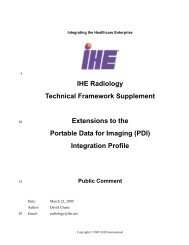
<strong>IHE</strong> <strong>Patient</strong> <strong>Care</strong> <strong>Device</strong> <strong>Technical</strong> <strong>Framework</strong>, Vol. 2: Transactions________________________________________________________________________3 Transactions3.1 PCD-01 Communicate PCD DataThis section corresponds to Transaction PCD-01 of the <strong>IHE</strong> <strong>Patient</strong> <strong>Care</strong> <strong>Device</strong><strong>Technical</strong> <strong>Framework</strong>. Transaction PCD-01 is used by the <strong>Device</strong> Observation Reporter,<strong>Device</strong> Observation Filter, and <strong>Device</strong> Observation Consumer actors.3.1.1 Scope10This transaction is used to communicate PCD Data from:• A <strong>Device</strong> Observation Reporter (DOR) to either a <strong>Device</strong> Observation Filter (DOF)or a <strong>Device</strong> Observation Consumer (DOC).• A <strong>Device</strong> Observation Filter (DOF) to a <strong>Device</strong> Observation Consumer (DOC).3.1.2 Use Case Roles<strong>Device</strong> Observation Consumer(DOC)CommunicatePCD Data<strong>Device</strong> Observation Filter(DOF)<strong>Device</strong> Observation Reporter(DOR)Figure 1 Communicate PCD Data Use CaseActor: <strong>Device</strong> Observation Reporter (DOR)Role: Sends PCD Data to DOF or to DOCActor: <strong>Device</strong> Observation Filter (DOF)Role: Receives PCD Data from DOR and sends PCD Data to DOC based on definedfilter predicates.Actor: <strong>Device</strong> Observation Consumer (DOC)14Rev. 1.1 TI: 2006-08-15Copyright © 2005-2006: ACC, ACCE, HIMSS, and RSNA
<strong>IHE</strong> <strong>Patient</strong> <strong>Care</strong> <strong>Device</strong> <strong>Technical</strong> <strong>Framework</strong>, Vol. 2: Transactions________________________________________________________________________Role: Receives PCD Data from DOR and/or DOF.3.1.3 Referenced Standards• HL7 - Health Level 7 Version 2.5 Ch7 Observation Reporting• ISO/IEEE 11073-10201 Domain Information Model• ISO/IEEE 11073-10101 Nomenclature3.1.4 Interaction DiagramsThe following interaction diagrams illustrate potential implementations.3.1.5 DOR communicates with DOC10The PCD-01 is used to communicate PCD data from: <strong>Device</strong> Observation Reporter(DOR) to a <strong>Device</strong> Observation Consumer (DOC).DOCDORPCD-01 Communicate PCD DataFigure 2 Communicate PCD Data Interaction Diagram3.1.6 Communicate Filtered PCD DataIn the communication of filtered PCD Data the DOF receives PCD data from the DORand communicates a selected set of the messages based upon a subscription which hasbeen set up as a result of a PCD-02: Subscribe to PCD Data transaction. The PCD-02transaction is shown for information in Figure 3 Communicate Filtered PCD Data and isdefined in section 3.2 Transaction PCD-02 Subscribe to PCD Data.Rev. 1.1 TI: 2006-08-1515Copyright © 2005-2006: ACC, ACCE, HIMSS, and RSNA
<strong>IHE</strong> <strong>Patient</strong> <strong>Care</strong> <strong>Device</strong> <strong>Technical</strong> <strong>Framework</strong>, Vol. 2: Transactions________________________________________________________________________DOCDOFDORPCD-02: Subscribeto PCD DataPCD-01CommunicatePCD DataPCD-01CommunicatePCD DataFigure 3 Communicate Filtered PCD Data3.1.7 PCD-01 Communicate PCD Data (ORU^R01^ORU_R01) staticdefinition10The PCD-01 Communicate PCD Data message is used to communicate PCD data• From a <strong>Device</strong> Observation Reporter (DOR) to a <strong>Device</strong> Observation Consumer(DOC).• From a <strong>Device</strong> Observation Reporter (DOR) to a <strong>Device</strong> Observation Filter(DOC).• From a <strong>Device</strong> Observation Filter (DOF) to a <strong>Device</strong> Observation Consumer(DOC).Common HL7 segments (MSH, MSA, ERR, NTE, PID, PV1, OBR, OBX, QPD, RCP,TQ1) and data types (CE, CQ,CX, EI, HD, PL, TS, XPN, XTN) used in <strong>IHE</strong> PCDtransactions are defined in Appendix B Common Message Segments for the <strong>Patient</strong> <strong>Care</strong><strong>Device</strong> <strong>Technical</strong> <strong>Framework</strong> and Appendix C Common Data Types.Table 1 ORU^R01^ORU_R01 static definitionSegment Meaning Usage Card. HL7 chapterMSH Message Header R [1..1] 2[{SFT}] Software Segment X [0..0] 2{ --- PATIENT_RESULT begin[ --- PATIENT beginPID <strong>Patient</strong> Identification R [1..1] 3[PD1] Additional Demographics X [0..0] 3..[{NTE}] Notes and Comments X [0 0] 216Rev. 1.1 TI: 2006-08-15Copyright © 2005-2006: ACC, ACCE, HIMSS, and RSNA
<strong>IHE</strong> <strong>Patient</strong> <strong>Care</strong> <strong>Device</strong> <strong>Technical</strong> <strong>Framework</strong>, Vol. 2: Transactions________________________________________________________________________..[{NK1}] Next of Kin/Associated Parties X [0..0] 3[ --- VISIT beginPV1 <strong>Patient</strong> Visit O [0..1] 3[PV2] <strong>Patient</strong> Visit – Additional Info X [0..0] 3] --- VISIT end] --- PATIENT end{ ---ORDER_OBSERVATION begin[ORC] Order Common X [0..0] 4OBR Observation Request R [1..1] 7[{NTE}] Notes and Comments O [0..1] 2[{ --- TIMING_QTY beginTQ1 Timing/Quantity O [0..1] 4[{TQ2}] Timing/Quantity Order Sequence X 4{] --- TIMING_QTY end[CTD] Contact Data X [0..0] 11[{ --- OBSERVATION beginOBX Observation Result R [1..1] 7[{NTE}] Notes and comments 2}] --- OBSERVATION end[{FT1}] Financial Transaction X [0..0] 6[{CTI}] Clinical Trial Identification X [0..0] 7[{ --- SPECIMEN beginSPM Specimen X [0..0] 7[{OBX}] Observation related to Specimen X [0..0] 7}] --- SPECIMEN end} --- ORDER_OBSERVATION end} --- PATIENT_RESULT end[DSC] Continuation Pointer X [0..0] 23.1.7.1 Trigger eventsThe ORU^R01_ORU_R01 message is an unsolicited update. An application whichimplements the DOR receives data from one or more PCDs using either standards basedor proprietary protocols which are outside the current scope of the <strong>IHE</strong> PCD TF.In general, the DOR sends periodic reports at a minimum interval of 10 seconds (highacuity) and a maximum interval of 24 hours (chronic, home health) with a typical intervalof 1 minute. The minimum and maximum intervals are configured at implementation.Rev. 1.1 TI: 2006-08-1517Copyright © 2005-2006: ACC, ACCE, HIMSS, and RSNA
<strong>IHE</strong> <strong>Patient</strong> <strong>Care</strong> <strong>Device</strong> <strong>Technical</strong> <strong>Framework</strong>, Vol. 2: Transactions________________________________________________________________________The DOR may also send aperiodic reports for "event type” information. The DOR doesnot do interpolation of data received from the PCD source.The DOF receives messages from the DOR and provides the same capabilities as theDOR regarding sending of reports. The DOR adds the service of filtering the messagestream based on a predicate negotiated at run-time.3.1.7.2 Message Semantics10Refer to the HL7 standard for the ORU message of HL7 2.5 Chapter 7 and the generalmessage semantics.The ORU^OR1^ORU_R01 message structure provides the mechanisms for mapping thehierarchical structure of an IEEE 11073 containment tree to a series of OBX messageseach of which is optionally qualified by an a note which immediately follows therespective OBX.See Appendix A ISO/IEEE Nomenclature mapping to HL7 OBX-3 for furtherinformation on the mapping rules.Examples of ORU^R01^ORU_R01 messages implemented in both HL7 ER and XMLare provided in Appendix E Examples of messages.3.1.7.3 Expected Action20The ORU^R01^ORU_R01 message is sent from the DOR to the DOC, DOF, or both.Upon receipt the DOC and DOF validate the message and respond with anacknowledgement as defined in Appendix G.2 Acknowledgment Modes.3.2 Transaction PCD-02 Subscribe to PCD Data30This section corresponds to Transaction PCD-02 of the <strong>IHE</strong> <strong>Patient</strong> <strong>Care</strong> <strong>Device</strong><strong>Technical</strong> <strong>Framework</strong>. Transaction PCD-02 is used by the <strong>Device</strong> Observation Filter, and<strong>Device</strong> Observation Consumer actors.Common HL7 segments (MSH, MSA, ERR, NTE, PID, PV1, OBR, OBX, QPD, RCP)and data types (CE, CX, EI, HD, PL, TS, XPN, XTN) used in <strong>IHE</strong> PCD transactions aredefined in Appendix B Common Message Segments for the <strong>Patient</strong> <strong>Care</strong> <strong>Device</strong><strong>Technical</strong> <strong>Framework</strong> and Appendix C Common Data Types.3.2.1 ScopeThis transaction is used by a <strong>Device</strong> Observation Consumer (DOC) to subscribe for PCDData from a <strong>Device</strong> Observation Filter (DOF).Rev. 1.1 TI: 2006-08-1518Copyright © 2005-2006: ACC, ACCE, HIMSS, and RSNA
<strong>IHE</strong> <strong>Patient</strong> <strong>Care</strong> <strong>Device</strong> <strong>Technical</strong> <strong>Framework</strong>, Vol. 2: Transactions________________________________________________________________________3.2.2 Use Case Roles<strong>Device</strong> Observation Consumer(DOC)Subscribe toPCD Data<strong>Device</strong> Observation Filter(DOF)Figure 4 Subscribe to PCD Data Use Case10Actor: <strong>Device</strong> Observation FilterRole: Receives subscription request from the DOC and sets up filtering such that onlythose PCD-01 messages which satisfy the filter predicates are communicated to the DOC.In the absence of any explicit predicates regarding starting and stopping, the DOF willstart as soon as the configuration of the predicate filters is completed and will continueuntil an explicit stop transaction is received. Each DOF is capable of supporting one ormore subscriptions from a DOC.Actor: <strong>Device</strong> Observation ConsumerRole: Subscribes to PCD data.3.2.3 Referenced Standards• HL7 - Health Level 7 Version 2.5 Ch5 Query and CH7 Observation Reporting• ISO/IEEE 11073-10201 Domain Information Model• ISO/IEEE 11073-10101 Nomenclature3.2.4 Interaction Diagram20The PCD-02 is used by a <strong>Device</strong> Observation Consumer (DOC) to subscribe for PCDData from a <strong>Device</strong> Observation Filter (DOF). The transaction is based on the HL7Publish and Subscribe Query model where the <strong>Device</strong> Observation Filter (DOF) plays therole of Publisher and the <strong>Device</strong> Observation Consumer (DOC) plays the role ofSubscriber. The DOF defines a stream of data, but also agrees to selectively subset theRev. 1.1 TI: 2006-08-1519Copyright © 2005-2006: ACC, ACCE, HIMSS, and RSNA
<strong>IHE</strong> <strong>Patient</strong> <strong>Care</strong> <strong>Device</strong> <strong>Technical</strong> <strong>Framework</strong>, Vol. 2: Transactions________________________________________________________________________message stream based on query-like data constraints. In the normal case, the right of theDOC to subscribe is decided at interface setup time. At runtime, the DOR controls thedata rules, based on the subscription, under which it sends messages. Prospective datamay be sent for a specified period of time, or for an open-ended period of time untilfurther notice. Specific messages have been defined for subscription and the canceling ofa subscription. See HL7 V2.5 Ch 5.7 for details of the Publish/Subscribe model.DOCDOFDORPCD-02: Subscribe toPCD DataPCD-01CommunicatePCD DataPCD-01CommunicatePCD DataFigure 5 Subscribe to PCD Data Interaction Diagram103.2.5 Message Static Definitions3.2.5.1 Conformance StatementThe HL7 Query model requires the definition of a Conformance Statement. Theconformance statement for the PCD-02 Subscribe to PCD Data transaction describedbelow is adapted from HL7 V2.5.Table 2 Conformance StatementPublication ID (Query ID=Z02):Type:Publication Name:Query Trigger (= MSH-9):Query Mode:Response Trigger (= MSH-9):Query Characteristics:Purpose:Z02Publish<strong>IHE</strong>PCD-02SubscribeToPCDDataQSB^Z02^QSB_Q16ImmediateORU^R01^ORU_R01 (PCD-01)Returns PCD data as defined by the query characteristicsCommunicate PCD data using the PCD-01 transaction, eitherRev. 1.1 TI: 2006-08-1520Copyright © 2005-2006: ACC, ACCE, HIMSS, and RSNA
<strong>IHE</strong> <strong>Patient</strong> <strong>Care</strong> <strong>Device</strong> <strong>Technical</strong> <strong>Framework</strong>, Vol. 2: Transactions________________________________________________________________________Publication ID (Query ID=Z02):Response Characteristics:Based on Segment Pattern:Z02filtered or unfiltered, as specified in the input parameters.PCD-01 ORU messages are returned corresponding to theconstraints expressed in the input parameters.The input parameters are ANDed when selecting data to bereturned. That is, all input parameters that are specified mustbe satisfied in order for a result report to be sent.Parameters that are left empty are ignored in defining thefilter criteriaR013.2.6 PCD-02 – QSB^Z02^QSB_Q16 static definitionCommon HL7 segments (MSH, MSA, ERR, NTE, PID, PV1, OBR, OBX, QPD, RCP,TQ1) and data types (CE, CQ,CX, EI, HD, PL, TS, XPN, XTN) used in <strong>IHE</strong> PCDtransactions are defined in Appendix B Common Message Segments for the <strong>Patient</strong> <strong>Care</strong><strong>Device</strong> <strong>Technical</strong> <strong>Framework</strong> and Appendix C Common Data Types.Table 3 PCD-02 - QSB^Z02^QSB_Q16 static definitionQSB^Z02^QSB_Q16 Query Grammar: QSB Message Usage Card. SectionRef.MSH Message Header Segment R [1..1] 2.15.9[{SFT}] Software Segment X [0..0] 2.15.12QPD Query Parameter Definition R [1..1] 5.5.4RCP Response Control Parameter R [1..1] Error!Referencesource notfound.[ DSC ] Continuation Pointer CE [0..1] 2.15.410The <strong>IHE</strong> PCD TF supports filtering based on the parameters defined in Table 4 QPDInput Parameter Specification and described in Table 5 QPD Input Parameter FieldDescripion and Commentary.Table 4 QPD Input Parameter SpecificationFieldSeq(QueryID=Z02)ColNameKey/SearchSortLEN DT OptRP/#MatchOpTBL #SegmentFieldNameServiceIdentifierCodeElementName1 MessageQueryName 60 CE R [1..1] MessageQueryNameRev. 1.1 TI: 2006-08-1521Copyright © 2005-2006: ACC, ACCE, HIMSS, and RSNA
<strong>IHE</strong> <strong>Patient</strong> <strong>Care</strong> <strong>Device</strong> <strong>Technical</strong> <strong>Framework</strong>, Vol. 2: Transactions________________________________________________________________________FieldSeq(QueryID=Z02)ColNameKey/SearchSortLEN DT OptRP/#MatchOpTBL #SegmentFieldNameServiceIdentifierCodeElementName2 QueryTag 32 ST R [1..1] QueryTag3 MRN CX O [0..20] PID.34 ActionCode ID O [0..1] 03235 <strong>Patient</strong>Location PL O [0..20] PV1.36 <strong>Device</strong>Class CE O [0..6] OBX.37 ParameterClass CE O [0..6] OBX.38 StartDateTime TS O [0..1] TQ1-79 EndDateTime TS O [0..1] TQ1-810 Interval CQ O [0..1] TQ1-5Input Parameter(Query ID=ZXX)Table 5 QPD Input Parameter Field Descripion and CommentaryComp.NameDTDescriptionMessageQueryName CE Must be valued Z02^PCD-02-Subscription.QueryTag ST Unique to each query message instance.MRN CX One or more patient identifiers may be sent. When a list is provided, resultswill be sent if any parameter matches any ID known for a patient. Sending novalue matches all patientsActionCode ID If the subscription is being modified, the desired action e.g., Add or Delete iscarried in this field. Must be ‘A’, ‘D’, or null.<strong>Patient</strong>Location PL When a list is provided, results will be sent if any parameter matches PV1.3for any result. Sending no value matches all results.<strong>Device</strong>Class IS When a list is provided, results will be sent if any parameter matches OBX.3for any result. Sending no value matches all results.ParameterClass CE When a list is provided, results will be sent if any parameter matches OBX.3for any result... Sending no value matches all results.StartDateTime TS The date/time at which the subscription is to start. If null subscription startsimmediatelyEndDateTime TS The date/time at which the subscription is to end. If null subscription startsimmediatelyInterval CQ The interval between observation reports.The <strong>IHE</strong> PCD TF supports the RCP response control parameters described in Table 6RCP Response Control Parameter Field Description and Commentary.Rev. 1.1 TI: 2006-08-1522Copyright © 2005-2006: ACC, ACCE, HIMSS, and RSNA
<strong>IHE</strong> <strong>Patient</strong> <strong>Care</strong> <strong>Device</strong> <strong>Technical</strong> <strong>Framework</strong>, Vol. 2: Transactions________________________________________________________________________Table 6 RCP Response Control Parameter Field Description and CommentaryFieldSeq(QueryID=Z99)NameComponentNameLEN DT Description1 Query Priority 1 ID I3 Response Modality 60 C RE3.2.6.1 Trigger eventsThe QSB^Z02^QSB_Q16 message is defined by the <strong>IHE</strong> PCD based on the rules definedin HL7 v2.5 Chapter 5.7 for Publish and Subscribe messages. The QSB^Z02^QSB_Q16is sent from a DOC to a DOF for the purpose of creating a new subscription or modifyingan existing subscription. Permission for a DOC to send the QSB^Z02^QSB_Q16 to aDOF is defined at implementation time.3.2.6.2 Message Semantics1020Refer to HL7 2.5 Chapter 5.4.4 for the general message semantics of the QSB messageand Chapter 5.7 for the details of Publish and Subscribe.The <strong>IHE</strong> PCD QSB^Z02^QSB_Q16 message defines the parameters which define thefilter to be applied to a stream of device observation messages. The current version of the<strong>IHE</strong> PCD TF provides facilities for selecting messages based on:• A list of one or more patients identified by a patient identifier• A list of one or more patient locations• A list of one or more device classes• A list of one of more specific device parameter classesThe <strong>IHE</strong> PCD QSB^Z02^QSB_Q16 also provides parameters which define the:• Date and time at which the subscription is to begin, the default is immediately.• Date and time at which the subscription is to end, the default is never.• The interval between periodic reports.The parameters of the QSB^Z02^QSB_Q16 are combined based on a logical AND todefine the overall query. For those parameters which define a list of one or more entriesthe elements of the list are combined based on a logical OR and satisfaction of anymember of the list satisfies the condition for the respective parameter.If the Action Code is set to A, the parameters are added to an existing subscription.If the Action Code is set to D, the parameters are deleted from an existing subscription.Rev. 1.1 TI: 2006-08-1523Copyright © 2005-2006: ACC, ACCE, HIMSS, and RSNA
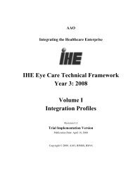
<strong>IHE</strong> <strong>Patient</strong> <strong>Care</strong> <strong>Device</strong> <strong>Technical</strong> <strong>Framework</strong>, Vol. 2: Transactions________________________________________________________________________3.2.6.3 Expected ActionUpon receipt of a QSB^Z02^QSB_Q16 the DOF establishes a subscription based on theparameters defined and communicates those messages satisfying the subscriptionpredicate using the PCD-01 transaction to the subscriber.1020Appendix AISO/IEEE 11073 Mapping to HL7IEEE 11073 defines PCD semantics in terms of an information model and anomenclature. The information model is defined in ISO/IEEE 11073-10201 HealthInformatics – Point-of-care medical device communication – Part 10201 : DomainInformation Model. The nomenclature is defined in ISO/IEEE 11073-10101 HealthInformatics – Point -of-care medical device communication – Part 10101: Nomenclature.Familiarity with these standards is necessary for implementers of the <strong>Device</strong> ObservationReporter and <strong>Device</strong> Observation Filter actors.HL7 V2.5 Chapter 7 Observation Reporting defines the syntax and coding requirementsused for PCD data communications in the PCD TF. Familiarity with HL7 Chapter 7 isnecessary for implementers of the PCD TF transactions.One of the key contributions of the PCD TF is the definition of common semantics forPCD data communication in the enterprise environment. This is accomplished by the<strong>Device</strong> Observation Reporter and <strong>Device</strong> Observation Filter actors through mapping ofthe IEEE 11073 semantics to equivalent elements of HL7.The purpose of this appendix is to describe the model which is used to map from IEEE11073 semantics to HL7.A.1 Mapping ISO/IEEE 11073 Domain Information Modelto HL7Figure 6 System Package Model represents the system level containment of the 11073DIM.Rev. 1.1 TI: 2006-08-1524Copyright © 2005-2006: ACC, ACCE, HIMSS, and RSNA
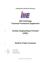
<strong>IHE</strong> <strong>Patient</strong> <strong>Care</strong> <strong>Device</strong> <strong>Technical</strong> <strong>Framework</strong>, Vol. 2: Transactions________________________________________________________________________Figure 6 System Package ModelMedicalPackageThe mapping from 11073 to HL7 will be described by focusing on the Medical Packagedefined by the Medical <strong>Device</strong> System shown in Figure 6 System Package Model andelaborated in Figure 7 Medical Package Model.Rev. 1.1 TI: 2006-08-1525Copyright © 2005-2006: ACC, ACCE, HIMSS, and RSNA
<strong>IHE</strong> <strong>Patient</strong> <strong>Care</strong> <strong>Device</strong> <strong>Technical</strong> <strong>Framework</strong>, Vol. 2: Transactions________________________________________________________________________10..nFigure 7 Medical Package Model10The HL7 OBX segment provides two fields which are used in mapping Figure 7 MedicalPackage Model, these are OBX-3 Observation Identifier and OBX-4 Observation Sub-Id.OBX-3 is expressed as an HL7 Coded Element (CE) datatype and the details of mappingthe 11073 MDC to the HL7 CE datatype are described in Appendix A.2 ISO/IEEENomenclature mapping to HL7 OBX-3.OBX-4 is used to express the containment level of a particular item expressed in OBX-3.This is done by defining the nodes of the hierarchy of the containment tree as a set of ordinal numbers expressed in a dottednotation such that each OBX-3 is expressed unambiguously in terms of its containment asdefined by OBX-4.Rev. 1.1 TI: 2006-08-1526Copyright © 2005-2006: ACC, ACCE, HIMSS, and RSNA
<strong>IHE</strong> <strong>Patient</strong> <strong>Care</strong> <strong>Device</strong> <strong>Technical</strong> <strong>Framework</strong>, Vol. 2: Transactions________________________________________________________________________SubjectContainment Tree Hierarchical LevelMedical:OBX-4Examples1Virtual (Medical)Ordinal11112Virtual (Medical)Ordinal11223Virtual (Medical)Ordinal1213Recommend that Ordinal value is unique among entire setFigure 8 Example of Mapping Containment to OBX-4For example the OBX-4 for the would be expressedas 1.2.1.3.10OBX-2 the valid HL7 types for the mapping are NM, ST, SN, CE, CF (String may havesome implied structure)The specification of the containment tree provides a mechanism to address dynamicconfiguration of a PCD. For example, a patient monitor may have one or more “plug-ins”which may be added to and removed from the patient monitor as the patient’s clinicalcondition changes. When a plug-in is removed the ordinal numbers previously assignedto that plug-in shall be reserved. Replacement of the plug-in shall result in the reassignmentof the reserved ordinal numbers to the plug-in which has been replaced.Addition of a new plug-in shall result in the assignment of ordinal numbers which havenot been reserved.A.2 ISO/IEEE Nomenclature mapping to HL7 OBX-320The ISO/IEEE Nomenclature provides an unambiguous coding which is mapped to HL7OBX-3 as follows:HL7 OBX-3 is of type CE consisting of:Rev. 1.1 TI: 2006-08-1527Copyright © 2005-2006: ACC, ACCE, HIMSS, and RSNA
<strong>IHE</strong> <strong>Patient</strong> <strong>Care</strong> <strong>Device</strong> <strong>Technical</strong> <strong>Framework</strong>, Vol. 2: Transactions________________________________________________________________________Table 7 HL7 Component Table - CE - Coded ElementSEQ LEN DT Usage Card. TBL# Component Comments SecNameRef1 20 ST R [1..1] Identifier Nomenclature 2.A.74Code2 199 ST R [1..1] Text Reference ID 2.A.743 20 ID R [1..1] 0396 Name of “MDC”2.A.35Coding System4 20 ST O [0..1] Alternate2.A.74Identifier5 199 ST O [0..1] Alternate Text 2.A.746 20 ID O [0..1] 0396 Name of2.A.35AlternateCoding System10Definition: This data type transmits codes and the text associated with the code.Maximum Length: 483Where:Nomenclature Code is the string representation of the decimal value corresponding to thecontext free 32 bit representation of the Nomenclature Code[context-free] Nomenclature Code == (Code Block number * 2 ** 16 ) + [contextsensitive],where [context-sensitive] is an offset, reflecting a particular variant of anassociated “discriminator”. The Reference ID is also modified to reflect the variant.For example, for the “<strong>Device</strong> Type” Nomenclature, the <strong>Device</strong> Type discriminator is asfollows:Ref ID variant Description Term CodeOffsetDEV Not-otherwise specified 0MDS Medical <strong>Device</strong> System 1VMD Virtual Medical <strong>Device</strong> 2CHAN Channel 3The context-free nomenclature code for a term in code block number 1 whose termcode=4104 is equal to (( 1 * 2 ** 16 ) + 4104) = 1*65536 + 4104 = 69640 (which uniquelyidentifies the SpO2 monitor term) with a Reference ID ofMDC_DEV_ANALY_SAT_O2. The context-sensitive form for the variant “MDS” isRev. 1.1 TI: 2006-08-1528Copyright © 2005-2006: ACC, ACCE, HIMSS, and RSNA
1020<strong>IHE</strong> <strong>Patient</strong> <strong>Care</strong> <strong>Device</strong> <strong>Technical</strong> <strong>Framework</strong>, Vol. 2: Transactions________________________________________________________________________“MDC_DEV_ANALY_SAT_O2_MDS (appending, of suffixing “MDS”), and the TermCode is 69640+1 = 69641 (adding the Term Code Offset to the base Term Code).The OBX-3 representation is “ 69641^MDC_DEV_ANALY_SAT_O2_MDS^MDC “The Virtual Medical <strong>Device</strong> variants are: MDC_DEV_ANALY_SAT_O2_VMD 69640,and “69642^ MDC_DEV_ANALY_SAT_O2_VMD^MDC” in OBX-3 representation.To distinguish between periodic and aperiodic data map from the IEEE 11073 MetricAccess to HL7 and code in OBX-17. This is used where you want to distinguish periodic,aperiodic etc. Metric Category also provides distinction between manual and automatic.MDS Status describes states - disconnected, configuring, operating, terminating,disassociated, reconfiguring. Relates to general question of alerts and events. Value,Units, and Observation Status will be mapped to the OBX-17 or OBX-8.MDS MODEL is used to provide device vendor/model and shall be mapped at the MDSlevel in the OBX with the value described by OBX-3.MDS DEVICE TYPE is used to describe the type of the PCD such as monitor, ventilator,infusion pump…and shall be mapped at the MDS level in the OBX with the valuedescribed by OBX-3.For PCDs with complex operation states such as an infusion pump with a set of states like"Stopped", "Infusing Primary", "Infusing Secondary", "Bolus", etc.. or a ventilator withstates "Standby", "Ventilating", etc. the <strong>Device</strong> Operational Status Enumeration Object ismapped to OBX-3.A.3 Mapping 11073 Value Types to HL7 OBX-2.There is an additional consideration when mapping 11073 units to HL7.HL7 OBX-2 defines the Value Type that is used to express the value in OBX-5 based onHL7 Table 0125.The PCD TF constrains the allowable value type to those shown in Table 8 PCDConstrained HL7 Table 0125Table 8 PCD Constrained HL7 Table 0125Value Description CommentCD Coded EntryCF Coded Element with Formatted ValuesDT DateED Encapsulated DataFT Formatted TextNM NumericPN Person NameRev. 1.1 TI: 2006-08-1529Copyright © 2005-2006: ACC, ACCE, HIMSS, and RSNA
<strong>IHE</strong> <strong>Patient</strong> <strong>Care</strong> <strong>Device</strong> <strong>Technical</strong> <strong>Framework</strong>, Vol. 2: Transactions________________________________________________________________________Value Description CommentSN Structured NumericST String DataTM TimeTS Time Stamp (Date and Time)XCN Extended Composite Name and Number forPersonsAppendix B Common Message Segments for the <strong>Patient</strong><strong>Care</strong> <strong>Device</strong> <strong>Technical</strong> <strong>Framework</strong>B.1 MSH - Message Header SegmentSee HL7 v2.5: chapter 2 (2.15 Message control)This segment defines the intent, source, destination, and some specifics of the syntax of amessage.Table 9 MSH - Message HeaderSEQ LEN DT Usage Card. TBL# ITEM# Element name1 1 ST R [1..1] 00001 Field Separator2 4 ST R [1..1] 00002 Encoding Characters3 227 HD R [1..1] 0361 00003 Sending Application4 227 HD ORE [0..1] 0362 00004 Sending Facility5 227 HD ORE [0..1] 0361 00005 Receiving Application6 227 HD ORE [0..1] 0362 00006 Receiving Facility7 26 TS R [1..1] 00007 Date/Time of Message8 40 ST X [0..0] 00008 Security9 15 MSG R [1..1] 00009 Message Type10 20 ST R [1..1] 00010 Message Control Id11 3 PT R [1..1] 00011 Processing Id12 60 VID R [1..1] 00012 Version ID13 15 NM RE [10..1] 00013 Sequence Number14 180 ST X [0..0] 00014 Continuation Pointer15 2 ID R [1..1] 0155 00015 Accept Acknowledgement Type16 2 ID R [1..1] 0155 00016 Application AcknowledgementType17 3 ID RE [0..1] 0399 00017 Country Code18 16 ID RE [0..1] 0211 00692 Character Set19 250 CE RE [0..1] 00693 Principal Language of Message20 20 ID X [0..0] 0356 01317 Alternate Character Set HandlingScheme21 427 EI R [1..1] 01598 Message Profile IdentifierRev. 1.1 TI: 2006-08-1530Copyright © 2005-2006: ACC, ACCE, HIMSS, and RSNA
<strong>IHE</strong> <strong>Patient</strong> <strong>Care</strong> <strong>Device</strong> <strong>Technical</strong> <strong>Framework</strong>, Vol. 2: Transactions________________________________________________________________________102030MSH-1 Field Separator, required:The <strong>IHE</strong> PCD <strong>Technical</strong> <strong>Framework</strong> requires that applications support HL7-recommended value that is | (ASCII 124).MSH-2 Encoding Characters, required:This field contains the four characters in the following order: the componentseparator, repetition separator, escape character, and subcomponent separator. The<strong>IHE</strong> PCD <strong>Technical</strong> <strong>Framework</strong> requires that applications support HL7-recommended values ^~\& (ASCII 94, 126, 92, and 38, respectively).MSH-3 Sending Application (HD), required:Components: ^ ^ First component (optional): Namespace ID. Locally unique name for applicationimplementing PCD actor(s).Second component (required): Universal ID expressed as string of hexadecimaldigits. Implementations of PCD actors shall use an EUI 64 identifier. The IEEEdefined 64-bit extended unique identifier (EUI-64) is a concatenation of the 24-bitcompany_id value by the IEEE Registration Authority and a 40-bit extensionidentifier assigned by the organization with that company_id assignment.Third component (required): EUI-64.MSH-4 Sending Facility (HD), required but may be empty:Components: ^ ^ For the <strong>IHE</strong> PCD <strong>Technical</strong> <strong>Framework</strong>, when populated, this field shall beimplemented as:First component (required): Namespace ID. The name of the organizational entityresponsible for the sending application.Second component (optional): The URI (OID) of the organizational entity responsiblefor the sending application.Third component (optional): The type of identification URI provided in the secondcomponent of this field. The codification of these three components is entirely sitedefined.It may be detailed in the national extensions of this framework.MSH-5 Receiving Application (HD), required but may be empty:Components: ^ ^ Rev. 1.1 TI: 2006-08-1531Copyright © 2005-2006: ACC, ACCE, HIMSS, and RSNA
102030<strong>IHE</strong> <strong>Patient</strong> <strong>Care</strong> <strong>Device</strong> <strong>Technical</strong> <strong>Framework</strong>, Vol. 2: Transactions________________________________________________________________________For the <strong>IHE</strong> PCD <strong>Technical</strong> <strong>Framework</strong>, when populated, this field shall beimplemented as:First component (required): Namespace ID. The name of the organizational entityresponsible for the receiving application.Second component (optional): The URI (OID) of the organizational entity responsiblefor the receiving application.Third component (optional): The type of identification URI provided in the secondcomponent of this field. The codification of these three components is entirely sitedefined.It may be detailed in the national extensions of this framework.MSH-6 Receiving Facility (HD), required but may be empty:Components: ^ ^ For the <strong>IHE</strong> PCD <strong>Technical</strong> <strong>Framework</strong>, when populated, this field shall beimplemented as:First component (required): Namespace ID. The name of the organizational entityresponsible for the receiving application.Second component (optional): The URI (e.g. OID) of the organizational entityresponsible for the receiving application.Third component (optional): The type of identification URI provided in the secondcomponent of this field. The codification of these three components is entirely sitedefined.It may be detailed in the national extensions of this framework.MSH-7 Date/Time of Message (TS), required:The <strong>IHE</strong> PCD TF requires this field be populated with:For the <strong>IHE</strong> PCD <strong>Technical</strong> <strong>Framework</strong>, when populated, this field shall beimplemented as:Format: YYYY[MM[DD[HH[MM[SS]]]]][+/-ZZZZ]Time zone qualification of the date/time is required.MSH-7 shall be used only to provide message created timeMSH-9 Message Type (MSG), required:Components: ^ ^ Definition: This field contains the message type, trigger event, and the messagestructure ID for the message. All three components are required.Its content is defined within each transaction-specific section of this document.Rev. 1.1 TI: 2006-08-1532Copyright © 2005-2006: ACC, ACCE, HIMSS, and RSNA
102030<strong>IHE</strong> <strong>Patient</strong> <strong>Care</strong> <strong>Device</strong> <strong>Technical</strong> <strong>Framework</strong>, Vol. 2: Transactions________________________________________________________________________MSH-10 Message Control Id (ST), required:Definition: This field contains a number or other identifier that uniquely identifiesthe message. Each message should be given a unique identifier by the sendingsystem. The receiving system shall echo this ID back to the sending system in theMessage Acknowledgment segment (MSA). The combination of this identifier andthe name of the sending application (MSH-3) shall be unique across the HealthcareEnterprise.MSH-11 Processing ID (PT), required:Components: ^ Definition: This data type indicates whether to process a message as defined in HL7Application (level 7) processing rules.The <strong>IHE</strong> PCD-TF requires the first component Processing ID be valued based onHL7 Table 0103. Use of the second component Processing Mode is optional but ifused is based on HL7 Table 0207.MSH-12 Version ID (VID), required:Components: ^ ^ Definition: This field is matched by the receiving system to its own version to be surethe message will be interpreted correctly.The PCD TF is based on HL7 V2.5. Where specific elements of V2.6 are requiredthey have been used and their usage flagged.Although HL7 allows international affiliate versions to be specified the <strong>IHE</strong> PCD-TFuses only the core version.MSH-13 Sequence Number (ID), required but may be empty:Definition: A non-null value in this field implies that the sequence number protocol isin use. This numeric field is incremented by one for each subsequent value.MSH-15 Accept Acknowledgement Type (ID), required:Definition: This field identifies the conditions under which accept acknowledgmentsare required to be returned in response to this message. Required for enhancedacknowledgment mode. Refer to HL7 Table 0155 - Accept/applicationacknowledgment conditions for valid values. The PCD TF requires that this field bevalued as NE.MSH-16 Application Acknowledgement Type (ID), required:Definition: This field identifies the conditions under which applicationacknowledgments are required to be returned in response to this message. RequiredRev. 1.1 TI: 2006-08-1533Copyright © 2005-2006: ACC, ACCE, HIMSS, and RSNA
10<strong>IHE</strong> <strong>Patient</strong> <strong>Care</strong> <strong>Device</strong> <strong>Technical</strong> <strong>Framework</strong>, Vol. 2: Transactions________________________________________________________________________for enhanced acknowledgment mode. Refer to HL7 Table 0155 - Accept/applicationacknowledgment conditions for valid values. The PCD TF requires that this field bevalued as AL.Note that the combination of MSH-16 valued as AL and MSH-15 valued as NE isconsistent with the original acknowledgement rules used in other <strong>IHE</strong> TFs.MSH-17 Country Code (ID), required but may be empty:Definition: This field contains the country of origin for the message. It will be usedprimarily to specify default elements, such as currency denominations. The values tobe used are those of ISO 3166,.5. The ISO 3166 table has three separate forms of thecountry code: HL7 specifies that the 3-character (alphabetic) form be used for thecountry code.2030Note that the combination of MSH-16 valued as AL and MSH-15 valued as NE isconsistent with the original acknowledgement rules used in other <strong>IHE</strong> TFs.MSH-18 Character Set (ID), required but may be empty:Definition: This field contains the character set for the entire message. Refer to HL7Table 0211 - Alternate character sets for valid values.An HL7 message uses field MSH-18-character set to specify the character set(s) inuse. Valid values for this field are specified in HL7 Table 0211, "Alternate CharacterSets". MSH-18-character set may be left blank, or may contain a single value. If thefield is left blank, the character set in use is understood to be the 7-bit ASCII set,decimal 0 through decimal 127 (hex 00 through hex 7F). This default value may alsobe explicitly specified as ASCII.Any encoding system, single-byte or multi-byte, may be specified as the defaultcharacter encoding in MSH-18-character set. If the default encoding is other than 7-bit ASCII, sites shall document this usage in the dynamic conformance profile orother implementation agreement. This is particularly effective in promotinginteroperability between nations belonging to different HL7 Affiliates, while limitingthe amount of testing required to determine the encoding of a message.By using built-in language functions for string and character manipulation, parsersand applications need not be concerned whether a single or double byte character setis in use, provided it is applied to the entire message. Using a built in function toextract the fourth CHARACTER will always yield the field separator character,regardless of coding set. On the other hand, if the parser looks at the fourth BYTE, itis then limited to single byte character sets, since the fourth byte would contain thelow order 8 bits of the character S in a double-byte system.See HL7 V2.5 for the semantics for alphabetic languages other than English(2.15.9.18.1) and for non-alphabetic languages (2.15.9.18.2)Rev. 1.1 TI: 2006-08-1534Copyright © 2005-2006: ACC, ACCE, HIMSS, and RSNA
1020<strong>IHE</strong> <strong>Patient</strong> <strong>Care</strong> <strong>Device</strong> <strong>Technical</strong> <strong>Framework</strong>, Vol. 2: Transactions________________________________________________________________________The PCD TF requires this field to be valued if the character set is other than ASCII. Ifthe character set is ASCII the field may be null or have the value of ASCII. A singlecharacter set is required for a given message.MSH-19 Principal Language of Message (RE), required but may be empty:Components: ^ ^ ^ ^ ^ Definition: This field contains the principal language of the message. Codes comefrom ISO 639.The PCD uses a default of EN^English^ISO659 if the field is empty.MSH-21 Message Profile Identifier (EI), required:Components: ^ ^ ^For PCD TF, this field is required. It is proposed that PCD message profiles beregistered with HL7 and that the appropriate ID be used here in conformant messagesWhen multiple message profiles are listed in this field they should be (vendorspecific, country specific) constraints of the PCD Profile. Note that the overriding ofPCD Profile constraints is only allowed in national extensions to this framework.The details for profile identification for Publish/Subscribe profiles are provided inSection 3.2 Transaction PCD-02 Subscribe to PCD DataB.2 MSA - Message Acknowledgement segmentHL7 v2.5: chapter 2 (2.15 Message control)This segment contains information sent while acknowledging another message.Table 10 MSA - Message AcknowledgementSEQ LEN DT Usage Card. TBL# ITEM# Element name1 2 ID R [1..1] 0008 00018 Acknowledgement code2 20 ST R [1..1] 00010 Message Control Id3 80 ST X [0..0] 00020 Text Message5 1 ID X [0..0] 00022 Delayed Acknowledgment Type6 250 CE X [0..0] 0357 00023 Error ConditionMSA-1 Acknowledgment Code (ID), required:Rev. 1.1 TI: 2006-08-1535Copyright © 2005-2006: ACC, ACCE, HIMSS, and RSNA
<strong>IHE</strong> <strong>Patient</strong> <strong>Care</strong> <strong>Device</strong> <strong>Technical</strong> <strong>Framework</strong>, Vol. 2: Transactions________________________________________________________________________The <strong>IHE</strong> PCD <strong>Technical</strong> <strong>Framework</strong> authorizes only one of the three values below,taken from HL7 table 0008 - Acknowledgement code:Table 11: HL7 table 0008 - Acknowledgement codeValue Description CommentAAAEAROriginal mode: ApplicationAcceptOriginal mode: ApplicationErrorOriginal mode: ApplicationRejectThe message has been accepted and integrated by the receivingapplicationThe sender should try again to send the message laterThe message has been rejected by the receiving applicationMSA-2 Message Control ID (ST), required:Definition: This field contains the message control ID from the MSH-10 - MessageControl ID of the incoming message for which the acknowledgement is sent.MSA-3 Text Message (ST), not supported:See the ERR segment.10B.3 ERR - Error segmentHL7 v2.5 : chapter 2 (2.15 Message control)This segment is used to add error comments to acknowledgment messages.Table 12 ERR - Error segmentSEQ LEN DT Usage Card. TBL# ITEM# Element name1 493 ELD RE [0..1] 00024 Error Code and Location3 705 CWE R [1..1] 0357 01813 HL7 Error Code4 2 ID R [1..1] 0516 01814 SeverityNotes: ERR-1 is included in HL7 v2.5 for backward compatibility only. Within the context of <strong>IHE</strong> PCD, thisfield shall not be used.ERR-3 and ERR-4 are required by HL7 v2.5B.4 NTE - Notes and Comment segment20HL7 v2.5 : chapter 2 (2.15 Message control)This segment is used for sending notes and comments.The <strong>IHE</strong> PCD <strong>Technical</strong> <strong>Framework</strong> limits the use of this segment to only onepurpose: To comment the observations and the orders. Therefore, in the messages ofthis Integration Profile, NTE segments appear only following either OBR or OBXsegments.Rev. 1.1 TI: 2006-08-1536Copyright © 2005-2006: ACC, ACCE, HIMSS, and RSNA
<strong>IHE</strong> <strong>Patient</strong> <strong>Care</strong> <strong>Device</strong> <strong>Technical</strong> <strong>Framework</strong>, Vol. 2: Transactions________________________________________________________________________Information that can be coded in OBX segments or OBR segments shall not be sent ina NTE segment.Detail of the fields used by the NTE segment in the PCD Observation Message isgiven in Error! Reference source not found.Table 13 NTE - Notes and Comment segmentSEQ LEN DT Usage Card. TBL# ITEM# Element name1 4 SI R [1..1] 00096 Set ID – NTE2 8 ID X [0..0] 00097 Source of Comment3 65536 FT RE [0..1] 00098 Comment4 250 CE X [0..0] 01318 Comment Type10NTE-1 Set ID - NTE (SI), required:NTE-3 Comment (FT), required but may be empty:This field contains the text of the comment. This text may be formatted. In order todelete an existing comment, the field shall contain empty quotation marks: “” .Comment text of identical type and source shall be included in the same occurrenceof an NTE segment, and not be split over multiple segments.B.5 PID - <strong>Patient</strong> Identification segmentHL7 v2.5 : chapter 3 (3.4.2)The PID segment is used by all applications as the primary means of communicatingpatient identification information. This segment contains permanent patient identifyingand demographic information that, for the most part, is not likely to change frequently.Table 14 PID - <strong>Patient</strong> Identification segmentSEQ LEN DT Usage Card. TBL# ITEM# Element name1 4 SI X [0..0] 00104 Set ID - PID2 20 CX X [0..0] 00105 <strong>Patient</strong> ID3 250 CX R [1..6] 00106 <strong>Patient</strong> Identifier List4 20 CX X [0..0] 00107 Alternate <strong>Patient</strong> ID - PID5 250 XPN R [1..6] 00108 <strong>Patient</strong> Name6 250 XPN RE [0..1] 00109 Mother’s Maiden Name7 26 TS RE [0..1] 00110 Date/Time of Birth8 1 IS RE [0..1] 0001 00111 Administrative Sex9 250 XPN X [0..0] 00112 <strong>Patient</strong> Alias10 250 CE RE [0..1] 0005 00113 Race11 250 XAD RE [0..1] 00114 <strong>Patient</strong> AddressRev. 1.1 TI: 2006-08-1537Copyright © 2005-2006: ACC, ACCE, HIMSS, and RSNA
<strong>IHE</strong> <strong>Patient</strong> <strong>Care</strong> <strong>Device</strong> <strong>Technical</strong> <strong>Framework</strong>, Vol. 2: Transactions________________________________________________________________________SEQ LEN DT Usage Card. TBL# ITEM# Element name12 4 IS RE [0..1] 0289 00115 County Code13 250 XTN RE [0..2] 00116 Phone Number - Home14 250 XTN X [0..1] 00117 Phone Number - Business15 250 CE RE [0..1] 0296 00118 Primary Language16 250 CE RE [0..1] 0002 00119 Marital Status17 250 CE RE [0..0] 0006 00120 Religion18 250 CX RE [0..1] 00121 <strong>Patient</strong> Account Number19 16 ST X [0..1] 00122 SSN Number - <strong>Patient</strong>20 25 DLN RE [0..1] 00123 Driver's License Number -<strong>Patient</strong>21 250 CX RE [0..1] 00124 Mother's Identifier22 250 CE RE [0..1] 0189 00125 Ethnic Group23 250 ST RE [0..1] 00126 Birth Place24 1 ID RE [0..1] 0136 00127 Multiple Birth Indicator25 2 NM RE [0..1] 00128 Birth Order26 250 CE RE [0..1] 0171 00129 Citizenship27 250 CE RE [0..1] 0172 00130 Veterans Military Status28 250 CE RE [0..1] 0212 00739 Nationality29 26 TS RE [0..1] 00740 <strong>Patient</strong> Death Date and Time30 1 ID RE [0..1] 0136 00741 <strong>Patient</strong> Death Indicator31 1 ID RE [0..1] 0136 01535 Identity Unknown Indicator32 20 IS RE [0..1] 0445 01536 Identity Reliability Code33 26 TS RE [0..1] 01537 Last Update Date/Time34 241 HD RE [0..1] 01538 Last Update Facility35 250 CE RE [0..1] 0446 01539 Species Code36 250 CE C [0..0] 0447 01540 Breed Code37 80 ST C [0..1] 01541 Strain38 250 CE RE [0..2] 0429 01542 Production Class Code39 250 CWE RE [0..1] 0171 01840 Tribal CitizenshipThe following describes the <strong>IHE</strong> PCD usage of those fields which have a usage otherthan X in the above table.PID-3 <strong>Patient</strong> Identifier List (CX), required:Definition: This field contains the list of identifiers (one or more) used by thehealthcare facility to uniquely identify a patient (e.g., medical record number, billingnumber, birth registry, national unique individual identifier, etc.). In Canada, theCanadian Provincial Healthcare Number shall be sent in this field.Rev. 1.1 TI: 2006-08-1538Copyright © 2005-2006: ACC, ACCE, HIMSS, and RSNA
102030<strong>IHE</strong> <strong>Patient</strong> <strong>Care</strong> <strong>Device</strong> <strong>Technical</strong> <strong>Framework</strong>, Vol. 2: Transactions________________________________________________________________________Subfields CX-1 “ID number”, CX-4 “Assigning authority”, and CX-5 “IdentifierType Code” are required for each identifier. See Appendix C.2 CX Data Type forfurther details.The workflow and mechanism by which patient identification is bound to the datafrom a particular PCD device is outside of the scope of this version of the <strong>IHE</strong> PCD<strong>Framework</strong>. Common implementations employ either automated or manual entrybased on information provided by an authoritative source of patient identity. Theworkflow and transactions to bind patient identity are included on the <strong>IHE</strong> PCDRoadmap for consideration in future versions of the <strong>IHE</strong> PCD <strong>Framework</strong>.The <strong>IHE</strong> PCD recognizes that for some use cases, such as medication administration,additional identification information or other patient demographic information isrequired in addition to an organizationally assigned unique identifier. <strong>Patient</strong> name,date of birth, gender, and other information are commonly used to provide theadditional patient identification context for these use cases. Additional patientdemographic information is provided by the fields of the PID segment and the patientlocation, which is often a key element in PCD communications, is provided in thePV1-3 element.PID-5 <strong>Patient</strong> Name (XPN), required:Definition: This field contains the names of the patient, the primary or legal name ofthe patient is reported first. Therefore, the name type code in this field should be “L -Legal”. Refer to Error! Reference source not found. for valid values. Note that “lastname prefix” is synonymous to “own family name prefix” of previous versions ofHL7, as is “second and further given names or initials thereof” to “middle initial orname”. Multiple given names and/or initials are separated by spaces.For animals, if a Name Type of “R” is used, use “Name Context” to identify theauthority with which the animal’s name is registered.The workflow and mechanism by which patient name is bound to the data from aparticular PCD device is outside of the scope of this version of the <strong>IHE</strong> PCD<strong>Framework</strong>. Common implementations employ either automated or manual entrybased on information provided by an authoritative source of patient identity. Theworkflow and transactions to bind patient name are included on the <strong>IHE</strong> PCDRoadmap for consideration in future versions of the <strong>IHE</strong> PCD <strong>Framework</strong>.See Appendix C.7 Type for further information.Table 15 HL7 Table 0200 - Name TypeValue Description CommentA Alias NameB Name at BirthC Adopted NameRev. 1.1 TI: 2006-08-1539Copyright © 2005-2006: ACC, ACCE, HIMSS, and RSNA
<strong>IHE</strong> <strong>Patient</strong> <strong>Care</strong> <strong>Device</strong> <strong>Technical</strong> <strong>Framework</strong>, Vol. 2: Transactions________________________________________________________________________D Display NameI Licensing NameL Legal NameM Maiden NameN Nickname /”Call me” Name/Street NameP Name of Partner/Spouse - obsolete Deprecated in V2.4R Registered Name (animals only)S Coded Pseudo-Name to ensure anonymityT Indigenous/Tribal/Community NameU Unspecified10PID-6 Mother’s Maiden Name (XPN), required but may be empty:Definition: This field contains the family name under which the mother was born(i.e., before marriage). It is used to distinguish between patients with the same lastname.See Appendix C.7 Type for further information.PID-7 Date/Time of Birth (TS), required but may be empty:For the <strong>IHE</strong> PCD <strong>Technical</strong> <strong>Framework</strong>, when populated, this field shall beimplemented as:Format: YYYY[MM[DD[HH[MM[SS]]]]][+/-ZZZZ]See Appendix C.6 TS Data Type for further information.PID-8: Administrative Sex (IS), required but may be empty:Definition: This field contains the patient’s sex. Refer to HL7 User-defined Table0001 - Administrative Sex for suggested values.Table 16 HL7 User Defined Table 0001 - Administrative SexValue Description CommentFMOANFemaleMaleOtherAmbiguousNot applicablePID-10: Race (CE), required but may be empty:Definition: This field refers to the patient’s race. Refer to User-defined Table 0005 -Race for suggested values. The second triplet of the CE data type for race (alternateidentifier, alternate text, and name of alternate coding system) is reserved forgovernmentally assigned codes.Rev. 1.1 TI: 2006-08-1540Copyright © 2005-2006: ACC, ACCE, HIMSS, and RSNA
<strong>IHE</strong> <strong>Patient</strong> <strong>Care</strong> <strong>Device</strong> <strong>Technical</strong> <strong>Framework</strong>, Vol. 2: Transactions________________________________________________________________________Table 17 HL7 User Defined Table 0005 - RaceValue Description Comment1002-5 American Indian of Alaska Native2028-9 Asian2054-5 Black or African American2076-8 Native Hawaiian of Other Pacific Islander2106-3 White2131-1 Other Race1020PID-11: <strong>Patient</strong> Address (XAD), required but may be empty:Components: ^ ^ ^ ^ ^ ^ ^ ^ ^ ^ ^ ^ ^ Subcomponents for Street Address (SAD): & & Subcomponents for Address Validity Range (DR): &Subcomponents for Range Start Date/Time (TS): & Subcomponents for Range End Date/Time (TS): & Subcomponents for Effective Date (TS): & Subcomponents for Expiration Date (TS): & Definition: This field contains the mailing address of the patient. Address type codesare defined by HL7 Table 0190 - Address Type. The PCD only requires the first,third, fourth, and fifth components to be valued with the mailing address and theAddress Type to be valued as M.PID-13: Phone Number – Home, required but may be empty:Definition: This field contains the patient’s personal phone numbers. This data type isusually in a repeatable field, to allow a list of numbers. The PCD requires thesequence to be the primary number (for backward compatibility). The PCD constrainsthis field to 2 repetitions to allow for a phone number and an email address.See Appendix C.8 XTN Data Type for further information.Rev. 1.1 TI: 2006-08-1541Copyright © 2005-2006: ACC, ACCE, HIMSS, and RSNA
102030<strong>IHE</strong> <strong>Patient</strong> <strong>Care</strong> <strong>Device</strong> <strong>Technical</strong> <strong>Framework</strong>, Vol. 2: Transactions________________________________________________________________________PID-15: Primary Language required but may be empty:See HL7 V2.5 Section 3.4.2.15 for details. The PCD TF requires the use of ISO639for the codes.PID-16: Marital StatusSee HL7 V2.5 Section 3.4.2.16 for details. The PCD TF does not further constrainthis field.PID-17: ReligionSee HL7 V2.5 Section 3.4.2.17 for details. The PCD TF does not further constrainthis field.PID-18: <strong>Patient</strong> Account Number (CX), required but may be empty:See HL7 V2.5 Section 3.4.2.18 for details. The PCD TF does not further constrainthis field. Additional requirements may be documented in Regional or Nationalappendices to the <strong>IHE</strong> PCD <strong>Technical</strong> <strong>Framework</strong>.PID-20: Driver’s License Number – <strong>Patient</strong> (CX), required but may be empty:See HL7 V2.5 Section 3.4.2.20 for details. The PCD TF does not further constrainthis field.PID-21: Mother’s Identifier (CX), required but may be empty:See HL7 V2.5 Section 3.4.2.21 for details. The PCD TF does not further constrainthis field.PID-22: Ethnic Group (CE), required but may be empty:See HL7 V2.5 Section 3.4.2.22 for details. The PCD TF does not further constrainthis field.PID-23: Birth Place (ST), required but may be empty:See HL7 V2.5 Section 3.4.2.23 for details. The PCD TF does not further constrainthis field.PID-24: Multiple Birth Indicator (ID), required but may be empty:See HL7 V2.5 Section 3.4.2.24 for details. The PCD TF does not further constrainthis field.PID-25: Birth Order (NM), required but may be empty:See HL7 V2.5 Section 3.4.2.25 for details. The PCD TF does not further constrainthis field.PID-26: Citizenship (CE), required but may be empty:Rev. 1.1 TI: 2006-08-1542Copyright © 2005-2006: ACC, ACCE, HIMSS, and RSNA
102030<strong>IHE</strong> <strong>Patient</strong> <strong>Care</strong> <strong>Device</strong> <strong>Technical</strong> <strong>Framework</strong>, Vol. 2: Transactions________________________________________________________________________See HL7 V2.5 Section 3.4.2.26 for details. The PCD TF does not further constrainthis field.PID-27: Veterans Military Status (CE), required but may be empty:See HL7 V2.5 Section 3.4.2.27 for details. The PCD TF does not further constrainthis field.PID-28: Nationality (CE), required but may be empty:See HL7 V2.5 Section 3.4.2.28 for details. The PCD TF does not further constrainthis field.PID-29: <strong>Patient</strong> Death Date and Time (TS), required but may be empty:Definition: This field contains the date and time at which the patient death occurred.See Appendix C.6 TS Data Type for PCD constraints.PID-30: <strong>Patient</strong> Death Indicator (ID), required but may be empty:See HL7 V2.5 Section 3.4.2.30 for details. The PCD TF does not further constrainthis field.PID-31: Identity Unknown Indicator (ID), required but may be empty:See HL7 V2.5 Section 3.4.2.31 for details. The PCD TF does not further constrainthis field.PID-32: Identity Reliability Code (IS), required but may be empty:See HL7 V2.5 Section 3.4.2.32 for details. The PCD TF does not further constrainthis field.PID-33: Last Update Date/Time (TS), required but may be empty:Definition: This field contains the last update date and time for the patient’s/person’sidentifying and demographic data, as defined in the PID segment. Receiving systemswill use this field to determine how to apply the transaction to their systems. If thereceiving system (such as an enterprise master patient index) already has a record forthe person with a later last update date/time, then the EMPI receiving system coulddecide not to apply the patient’s/person’s demographic and identifying data from thistransaction.See Appendix C.6 TS Data Type for PCD constraints.PID-34: Last Update Facility (HD), required but may be empty:See HL7 V2.5 Section 3.4.2.34 for details. The PCD TF does not further constrainthis field.PID-35: Species Code (CE), required but may be empty:Rev. 1.1 TI: 2006-08-1543Copyright © 2005-2006: ACC, ACCE, HIMSS, and RSNA
10<strong>IHE</strong> <strong>Patient</strong> <strong>Care</strong> <strong>Device</strong> <strong>Technical</strong> <strong>Framework</strong>, Vol. 2: Transactions________________________________________________________________________See HL7 V2.5 Section 3.4.2.35 for details. The PCD TF does not further constrainthis field.PID-36: Breed Code (CE), conditional.See HL7 V2.5 Section 3.4.2.36 for details. The PCD TF does not further constrainthis field.PID-37: Strain (ST), conditional.See HL7 V2.5 Section 3.4.2.37 for details. The PCD TF does not further constrainthis field.PID-38: Production Class Code (CE), required but may be empty:See HL7 V2.5 Section 3.4.2.38 for details. The PCD TF does not further constrainthis field.PID-39: Tribal Citizenship (CWE), required but may be empty:See HL7 V2.5 Section 3.4.2.39 for details. The PCD TF does not further constrainthis field.B.6 PV1 - <strong>Patient</strong> Visit Segment2030See HL7 V2.5 Section 3.4.3 for details.The PV1 segment is used by Registration/<strong>Patient</strong> Administration applications tocommunicate information on an account or visit-specific basis. The default is to sendaccount level data. To use this segment for visit level data PV1-51 - Visit Indicator mustbe valued to ‘V’. The value of PV-51 affects the level of data being sent on the PV1,PV2, and any other segments that are part of the associated PV1 hierarchy (e.g. ROL,DG1, or OBX).The facility ID, the optional fourth component of each patient location field, is a HD datatype that is uniquely associated with the healthcare facility containing the location. Agiven institution, or group of intercommunicating institutions, should establish a list offacilities that may be potential assignors of patient locations. The list will be one of theinstitution’s master dictionary lists. Since third parties other than the assignors of patientlocations may send or receive HL7 messages containing patient locations, the facility IDin the patient location may not be the same as that implied by the sending and receivingsystems identified in the MSH. The facility ID must be unique across facilities at a givensite. This field is required for HL7 implementations that have more than a singlehealthcare facility with bed locations, since the same ^ ^ combination may exist at more than one facility.Details of the PV1 segment as used in the <strong>IHE</strong> PCD <strong>Technical</strong> <strong>Framework</strong> are given inError! Reference source not found..Rev. 1.1 TI: 2006-08-1544Copyright © 2005-2006: ACC, ACCE, HIMSS, and RSNA
<strong>IHE</strong> <strong>Patient</strong> <strong>Care</strong> <strong>Device</strong> <strong>Technical</strong> <strong>Framework</strong>, Vol. 2: Transactions________________________________________________________________________Table 18 HL7 Attribute Table - PV1 - <strong>Patient</strong> VisitSEQ LEN DT Usage Card. TBL# ITEM# Element name1 4 SI X [0..0] 00131 Set ID - PV12 1 IS R [1..1] 0004 00132 <strong>Patient</strong> Class3 80 PL RE [0..1] 00133 Assigned <strong>Patient</strong> Location4 2 IS X [0..0] 0007 00134 Admission Type5 250 CX X [0..0] 00135 Preadmit Number6 80 PL X [0..0] 00136 Prior <strong>Patient</strong> Location7 250 XCN X [0..0] 0010 00137 Attending Doctor8 250 XCN X [0..0] 0010 00138 Referring Doctor9 250 XCN X [0..0] 0010 00139 Consulting Doctor10 3 IS X [0..0] 0069 00140 Hospital Service11 80 PL X [0..0] 00141 Temporary Location12 2 IS X [0..0] 0087 00142 Preadmit Test Indicator13 2 IS X [0..0] 0092 00143 Re-admission Indicator14 6 IS X [0..0] 0023 00144 Admit Source15 2 IS X [0..0] 0009 00145 Ambulatory Status16 2 IS X [0..0] 0099 00146 VIP Indicator17 250 XCN X [0..0] 0010 00147 Admitting Doctor18 2 IS X [0..0] 0018 00148 <strong>Patient</strong> Type19 250 CX RE [0..1] 00149 Visit Number20 50 FC X [0..0] 0064 00150 Financial Class21 2 IS X [0..0] 0032 00151 Charge Price Indicator22 2 IS X [0..0] 0045 00152 Courtesy Code23 2 IS X [0..0] 0046 00153 Credit Rating24 2 IS X [0..0] 0044 00154 Contract Code25 8 DT X [0..0] 00155 Contract Effective Date26 12 NM X [0..0] 00156 Contract Amount27 3 NM X [0..0] 00157 Contract Period28 2 IS X [0..0] 0073 00158 Interest Code29 4 IS X [0..0] 0110 00159 Transfer to Bad Debt Code30 8 DT X [0..0] 00160 Transfer to Bad Debt Date31 10 IS X [0..0] 0021 00161 Bad Debt Agency Code32 12 NM X [0..0] 00162 Bad Debt Transfer Amount33 12 NM X [0..0] 00163 Bad Debt Recovery Amount34 1 IS X [0..0] 0111 00164 Delete Account Indicator35 8 DT X [0..0] 00165 Delete Account Date36 3 IS X [0..0] 0112 00166 Discharge Disposition37 47 DLD X [0..0] 0113 00167 Discharged to LocationRev. 1.1 TI: 2006-08-1545Copyright © 2005-2006: ACC, ACCE, HIMSS, and RSNA
<strong>IHE</strong> <strong>Patient</strong> <strong>Care</strong> <strong>Device</strong> <strong>Technical</strong> <strong>Framework</strong>, Vol. 2: Transactions________________________________________________________________________SEQ LEN DT Usage Card. TBL# ITEM# Element name38 250 CE X [0..0] 0114 00168 Diet Type39 2 IS X [0..0] 0115 00169 Servicing Facility40 1 IS X [0..0] 0116 00170 Bed Status41 2 IS X [0..0] 0117 00171 Account Status42 80 PL X [0..0] 00172 Pending Location43 80 PL X [0..0] 00173 Prior Temporary Location44 26 TS X [0..0] 00174 Admit Date/Time45 26 TS X [0..0] 00175 Discharge Date/Time46 12 NM X [0..0] 00176 Current <strong>Patient</strong> Balance47 12 NM X [0..0] 00177 Total Charges48 12 NM X [0..0] 00178 Total Adjustments49 12 NM X [0..0] 00179 Total Payments50 250 CX X [0..1] 0203 00180 Alternate Visit ID51 1 IS RE [0..1] 0326 01226 Visit Indicator10PV1-2: <strong>Patient</strong> Class (IS), requiredDefinition: This field is used by systems to categorize patients by site. It does nothave a consistent industry-wide definition. It is subject to site-specific variations.Refer to HL7User-defined Table 0004 - <strong>Patient</strong> Class for <strong>IHE</strong> PCD suggested values.Table 19 HL7 User-defined Table 0004 - <strong>Patient</strong> ClassValue Description CommentEIOPRBUEmergencyInpatientOutpatientPreadmitRecurring patientObstetricsUnknownPV1-3: Assigned Location (PL), required but may be empty:<strong>IHE</strong> PCD definition: This field contains the patient’s initial assigned location or thelocation to which the patient is being moved. The first component may be the nursingstation for inpatient locations, or clinic or department, for locations other thaninpatient.For <strong>IHE</strong> PCD usage see Appendix C.5 PL Data Type.PV1-19: Visit Number (CX), required but may be empty:<strong>IHE</strong> PCD definition: This field contains the unique number assigned to each patientvisit.For <strong>IHE</strong> PCD usage see Appendix C.2 CX Data TypeRev. 1.1 TI: 2006-08-1546Copyright © 2005-2006: ACC, ACCE, HIMSS, and RSNA
<strong>IHE</strong> <strong>Patient</strong> <strong>Care</strong> <strong>Device</strong> <strong>Technical</strong> <strong>Framework</strong>, Vol. 2: Transactions________________________________________________________________________PV1-51: Visit Indicator (IS), required but may be empty:HL7 definition: This field specifies the level on which data are being sent. It is theindicator used to send data at two levels, visit and account. <strong>IHE</strong> PCD implementationsshall send an ‘A’ or no value when the data in the message are at the account level, or ‘V’to indicate that the data sent in the message are at the visit level.The value of this element affects the context of data sent in PV1, PV2 and any associatedhierarchical segments (e.g. DB1, AL1, DG1, etc.).B.7 OBR – Observation Request segment1020In the reporting of clinical data, the Observation Request Segment (OBR) serves as thereport header. It identifies the observation set represented by the following atomicobservations. It includes the relevant ordering information when that applies and manyof the attributes that apply to all of the following observations.Use as specified in HL7 – place here all header information for report content – asdistinct from MSH above which covers both patient and report info. Details of the OBRfields used in the <strong>IHE</strong> PCD <strong>Technical</strong> <strong>Framework</strong> are given in Error! Reference sourcenot found..Details of the fields used in the <strong>Patient</strong> <strong>Care</strong> <strong>Device</strong> Observation Message are given inError! Reference source not found..Table 20 OBR segmentSEQ LEN DT Usage Card. TBL# ITEM# Element name1 4 SI R [1..1] 00237 Set ID OBR2 427 EI R [1..1] 00216 Placer Order Number3 427 EI R [1..1] 00217 Filler Order Number4 250 CE R [1..1] 00238 Universal Service Identifier5 2 ID X [0..0] 00239 Priority - OBR6 26 TS X [0..0] 00240 Requested Date/Time7 26 TS RE [0..1] 00241 Observation Date/TimeOBR-1: Set ID OBR (SI), required:Definition: For the first order transmitted, the sequence number shall be 1; for thesecond order, it shall be 2; and so on.OBR-2: Placer Order Number (EI), required:Definition: This field is a case of the Entity Identifier data type. The first componentis a string that identifies an individual order (e.g., OBR). It is assigned by the place(ordering application). It identifies an order uniquely among all orders from aparticular ordering application. The second through fourth components contain theapplication ID of the placing application in the same form as the HD data type. TheRev. 1.1 TI: 2006-08-1547Copyright © 2005-2006: ACC, ACCE, HIMSS, and RSNA
10203040<strong>IHE</strong> <strong>Patient</strong> <strong>Care</strong> <strong>Device</strong> <strong>Technical</strong> <strong>Framework</strong>, Vol. 2: Transactions________________________________________________________________________second component, namespace ID, is a user-defined coded value that will be uniquelyassociated with an application. A given institution or group of intercommunicatinginstitutions should establish a unique list of applications that may be potential placersand fillers and assign unique application IDs. The components are separated bycomponent delimiters.The PCD TF does not use the ORC segment and, based on the HL7 rules, the OBR-2field must be valued. For the PCD TF the usual case is that PCD data is the result of a“standing order” and there is not a unique order associated with each instance ofcommunication of PCD data. In general, there is not a Placer (ordering application).The PCD TF requires the first and second components be valued. and recommendsthat the second component shall refer to the locally unique application identifierassigned to the <strong>Device</strong> Observation Reporter or <strong>Device</strong> Observation Filterapplications implementing <strong>IHE</strong> PCD actors which fill the role of an orderingapplication such as the DOR and DOF. The PCD TF requires that the thirdcomponent be valued with the EUI-64 code for the respective <strong>Device</strong> ObservationReporter or <strong>Device</strong> Observation Filter application implementing the respective <strong>IHE</strong>PCD actors which fill the role of an ordering application and the coding scheme beidentified as EUI-64. The PCD specifies the length of the OBR-2 as 427 which isconsistent with the defined length of the EI data type and with the OBR-2 lengthrecommended in HL7 V2.6.See Appendix C.3 EI Data Type for further information.OBR-3: Filler Order Number (EI), required:Definition: This field is the order number associated with the filling application. Thisis a permanent identifier for an order and its associated observations. It is a specialcase of the Entity Identifier data type. The first component is a string that identifies anorder detail segment (e.g., OBR). It is assigned by the order filler (receiving)application. This string must uniquely identify the order (as specified in the orderdetail segment) from other orders in a particular filling application (e.g., clinicallaboratory). This uniqueness must persist over time. The second through fourthcomponents contain the filler application ID, in the form of the HD data type. Thesecond component is a user-defined coded value that uniquely defines the applicationfrom other applications on the network. The second component of the filler ordernumber always identifies the actual filler of an order.The PCD TF requires the first and second components be valued and recommendsthat the second component refer to the locally unique application identifier assignedto the application implementing <strong>IHE</strong> actors supporting the role of an order filler suchas the DOR and DOF. <strong>Device</strong> Observation Reporter or <strong>Device</strong> Observation Filter.The PCD TF requires that the third component be valued with the EUI-64 code forthe respective <strong>Device</strong> Observation Reporter or <strong>Device</strong> Observation Filter and thecoding scheme be identified as EUI-64. The PCD specifies the length of the OBR-2Rev. 1.1 TI: 2006-08-1548Copyright © 2005-2006: ACC, ACCE, HIMSS, and RSNA
1020<strong>IHE</strong> <strong>Patient</strong> <strong>Care</strong> <strong>Device</strong> <strong>Technical</strong> <strong>Framework</strong>, Vol. 2: Transactions________________________________________________________________________as 427 which is consistent with the defined length of the EI data type and with theOBR-2 length recommended in HL7 V2.6.See Appendix C.3 EI Data Type for further information.OBR-4: Universal Service ID (CE), required:Definition: This field contains the identifier code for the requestedobservation/test/battery. This can be based on local and/or “universal” codes. Werecommend the “universal” procedure identifier.In general PCD communications occur as a result of “standing orders” and thespecific clinical reason for a particular PCD measurement is not known to the <strong>Device</strong>Observation Reporter or <strong>Device</strong> Observation Filter actor. In this case the PCD<strong>Framework</strong> recommends this field to be mapped at the highest level of containmentwithout additional specification for the system which is the source of the relatedOBXs.See Appendix A ISO/IEEE 11073 Mapping to HL7 for further details.See HL7 V2.5 Section 7.4.1.4 for details related to OBR-4.OBR-7: Observation Date/Time (TS), required:Time zone qualification of the date/time is optional. If the time zone is omitted fromthe message, ‘local time’ (time zone where the <strong>Device</strong> is located) is assumed.Local time is assumed to be valid.Resolution to seconds allows neonatal and OR messages at 10 second frequency,most other uses are not more than 60 second frequency.Format: YYYY[MM[DD[HH[MM[SS]]]]][+/-ZZZZ] where the time zone isoptional.For the DEC Profile PCD messages should be sent at a frequency of not more than onevery 10 seconds.See Appendix C.6 TS Data Type for further details.B.8 OBX - Observation/Result segment30Refer to HL7 v2.5: Section 7.4.2The HL7 OBX segment is used to transmit a single observation or observation fragment.Details of the fields used by the OBX segment in the PCD Observation/Result Messageare given in Error! Reference source not found..It is important to note that the values used for the OBX fields depend upon if the OBX isbeing used to provide information about the device(s) from which measurements arederived or to provide information related to the measurement metrics and relatedRev. 1.1 TI: 2006-08-1549Copyright © 2005-2006: ACC, ACCE, HIMSS, and RSNA
<strong>IHE</strong> <strong>Patient</strong> <strong>Care</strong> <strong>Device</strong> <strong>Technical</strong> <strong>Framework</strong>, Vol. 2: Transactions________________________________________________________________________information. Where this is the case the <strong>IHE</strong> PCD TF defines the appropriate coding forusage in a device related or metric related context. Each OBX shall be coded for aspecific context – device related or metric related.Table 21 OBX segmentSEQ LEN DT Usage Card. TBL# ITEM# Element name1 4 SI R [1..1] 00569 Set ID – OBX2 2 ID C [0..1] 0125 00570 Value Type3 250 CE R [1..1] 00571 Observation Identifier4 20 ST R [1..1] 00572 Observation Sub-ID5 99999 Varies C [0..1] 00573 Observation Value6 250 CE C [0..1] 00574 Units7 60 ST CE [0..1] 00575 References Range8 5 IS CE [0..1] 0078 00576 Abnormal Flags9 5 NM X [0..0] 00577 Probability10 2 ID CE [0..1] 0080 00578 Nature of Abnormal Test11 1 ID R [1..1] 0085 00579 Observation Result Status12 26 TS X [0..0] 00580 Effective Date of Reference Range13 20 ST X [0..0] 00581 User Defined Access Checks14 26 TS RE [0..1] 00582 Date/Time of the Observation15 250 CE RE [0..1] 00583 Producer's ID16 250 XCN RE [0..1] 00584 Responsible Observer17 250 CE RE [0..1] 00936 Observation Method18 22 EI RE [0..1] 01479 Equipment Instance Identifier19 26 TS CE [0..1] 01480 Date/Time of the Analysis20 705 CWE RE [0..*] 0163 02179 Observation Site10OBX-1 Set ID - OBX (SI), required:This field contains the sequence number of the OBX in this message; i.e. 1 st OBX SetID = 1, 2 nd OBX set_ID = 2, etc., regardless of whether the OBX refers to a device ora metric value.OBX-2 Value Type (ID), required:Condition Predicate: must be valued if the value of OBX-11 is not X.The Value Type field shall be filled according to HL7 Version 2.5 standard (table0125). For example, if the result is ">300" the Value Type "SN" (StructuredNumeric) SHALL be used instead of the "ST" (String) value type that was used inprevious versions of HL7. See the details and the examples in the HL7 V2.5 (7.4.2).For an observation that consists of a time measurement (e.g. bleeding time) the TMValue Type is preferred to NM but this is not made mandatory.Refer to TF-3 for details of the data types used in the mappings.Rev. 1.1 TI: 2006-08-1550Copyright © 2005-2006: ACC, ACCE, HIMSS, and RSNA
102030<strong>IHE</strong> <strong>Patient</strong> <strong>Care</strong> <strong>Device</strong> <strong>Technical</strong> <strong>Framework</strong>, Vol. 2: Transactions________________________________________________________________________OBX-3 Observation Identifier (CE), required:Identifies the type of device providing the related values. This is required ifstructured device (and if relevant, subdevice) identification is provided in themessage. For the PDC TF This shall be used for all devices capable of providingstructured device information. The preferred format is an MDC value, secondly aLOINC value.See Appendix A ISO/IEEE 11073 Mapping to HL7 for further details.OBX-4 Observation Sub-ID (ST), required:Condition predicate: This field shall be used to distinguish between multiple OBXsegments by providing an unambiguous mapping from the IEEE 11073 containmenttree. For device related data this field is used to group devices hierarchically. Formetric related data this field is used to associate metrics to devices hierarchically, andto each other. The dotted notation provided for in HL7 Ch7, 7.4.2.4, Fig 4 shall beused as follows: ... .See Appendix A ISO/IEEE 11073 Mapping to HL7 for further details.OBX-5 Observation Value (varies), conditional.Definition: This field contains the value observed by the observation producer. OBX-2-value type contains the data type for this field according to which observation valueis formatted. It is not a required field because some systems will report only thenormalcy/abnormalcy (OBX-8), especially in product experience reporting. Thelength of the observation field is variable, depending upon OBX-3-value type. Thisfield may repeat for multipart, single answer results with appropriate data types, e.g.,CE, TX, and FT data types.For the PCD TF this field is required for metric related segments and is null fordevice related segments. The preferred format, if valued, is an MDC value, secondlya LOINC value.OBX-6 Units (CE), conditionalSee HL7 2.5 Section 7.4.2.6 for further information.For the PCD TF:Condition predicate: If OBS-5 is populated then populate. For <strong>Device</strong> Related ifOBX-7 is being used for operating range then populate.The preferred format is an MDC value, secondly a LOINC value. however, othercoding systems or local names may be used.OBX-7 References Range (ST), required if available.For the PCD TF the preferred format is an MDC value, secondly a LOINC value. Fordevice related segments although not strictly a reference range this may be used toRev. 1.1 TI: 2006-08-1551Copyright © 2005-2006: ACC, ACCE, HIMSS, and RSNA
1020<strong>IHE</strong> <strong>Patient</strong> <strong>Care</strong> <strong>Device</strong> <strong>Technical</strong> <strong>Framework</strong>, Vol. 2: Transactions________________________________________________________________________provide the device measurement range capability – NOT the metric value ‘alarm’ranges which shall be in the appropriate observed value metric OBX. For metricrelated segments although not strictly a reference range in the sense of the examplesgiven in HL7 this should be used to provide the value ‘alarm’ ranges set with respectto the observed value metric in this OBX.OBX-8 Abnormal Flags (IS), required but may be empty:For the PCD TF the preferred format is an MDC value, secondly a LOINC value.This represents a PCD TF recommendation for HL7 User Table 0078. For devicerelated segments use for device status alerts – not the value “alert” flags which shouldbe in the appropriate observed metric value OBX. For Metric related segments use forobserved value metric status alerts with respect to the observed value metric in thisOBX.OBX-11 Observation Result Status (ID), required:This field should be filled according to HL7 Table 0085 described in Chapter 7 ofHL7. For the <strong>IHE</strong> PCD TF, the possible values for this field for this profile are shownin Error! Reference source not found.. The value of X is used for device relatedsegments where OBX-7 is not used to express the device measurement rangecapability.Table 22 HL7 Table 0085 selected valuesValue Description CommentC Record coming over is a correction andthus replaces a final resultD Deletes the OBX recordF Final results; Can only be changed witha corrected result.P Preliminary resultsR Results entered -- not verifiedS Partial resultsU Results status change to final withoutretransmitting results already sent as‘preliminary.’W Post original as wrong, e.g., transmittedfor wrong patientX Results cannot be obtained for thisobservationOBX-14 Date/Time of the Observation (TS), required but may be empty:For the PCD TF the value is the same as OBX19, but should be used in preference toOBX19 if time is relevant. Information may be duplicated in OBX19 if local needsdictateOBX-16 Responsible Observer (XCN), required but may be empty:Rev. 1.1 TI: 2006-08-1552Copyright © 2005-2006: ACC, ACCE, HIMSS, and RSNA
10<strong>IHE</strong> <strong>Patient</strong> <strong>Care</strong> <strong>Device</strong> <strong>Technical</strong> <strong>Framework</strong>, Vol. 2: Transactions________________________________________________________________________For the PCD TF:The identifier values for the Operator ID field may null, if unknown or unspecified atthe sending device.This field should be sent at the highest level of device related OBX possible: i.e.MDS, then VMD, and then Channel. Inheritance should be assumed; i.e. formultivalued results from the same <strong>Device</strong>, this field is required only in the first OBXsegment.For device related segments this should only be sent if no device related OBXsprecede this metric OBX.Table 23 extended composite ID number and name for personsSEQ LEN DT Usage Card. TBL# Component name1 15 ST R [1.1]2 194 FN RE [0..1]3 30 ST RE [0..1]2030OBX-17 Observation Method (CE), conditional:For the PCD TF:For device related segments observation methods are explicit in MDCRef_ID/codes; use of OBX17 is superfluous in device related OBX. Although notstrictly a reference range in the sense of the examples given in HL7 this should beused to provide the value ‘alarm’ ranges set with respect to the observed valuemetric in this OBX.For metric related segments observation methods are explicit in device relatedMDC Ref_ID/codes; use of OBX17 is superfluous if given there. However, ifobservation method is needed and no device detail is shown then the method shallbe given here.The preferred format is an MDC value, secondly a LOINC value.OBX-18 Equipment Instance Identifier (EI), required but may be empty:For the PCD TF:The preferred format is an EUI64 <strong>Device</strong> ID. The <strong>Device</strong> Identifier should beglobally unique.Every device be should identified by a universally unique identifier in the formatspecified by IEEE for the EUI64 identifier (e.g., “1234567890ABCDEF”). Toallow the Observation Reporting interface to be employed with ‘legacy’ <strong>Device</strong>s,this field may also be populated by a combination of <strong>Device</strong> name and serialnumber. If the EUI64 identifier is available, it should be recorded in the ‘universalID’ component of this field. If it is not available, the manufacturer’s <strong>Device</strong>Rev. 1.1 TI: 2006-08-1553Copyright © 2005-2006: ACC, ACCE, HIMSS, and RSNA
102030<strong>IHE</strong> <strong>Patient</strong> <strong>Care</strong> <strong>Device</strong> <strong>Technical</strong> <strong>Framework</strong>, Vol. 2: Transactions________________________________________________________________________identifier (e.g., serial number) should be recorded in ‘universal ID’ component,with the <strong>Device</strong> or manufacturer name in ‘universal ID type’ component.Should be sent at the highest level of device related OBX possible: i.e. MDS, thenVMD, and then Channel. Inheritance should be assumed; i.e. for multivaluedresults from the same <strong>Device</strong>, this field is required only in the first OBX segment.For metric related data this field is not required – unless no device hierarchy, andtherefore related OBXs, is being declared; in which case the device ID should beprovided here if available. Inheritance should be assumed; i.e. for multivaluedresults from the same <strong>Device</strong>, this field is required only in the first OBX segmentOBX-19 Date/Time of the Analysis (TS), conditional may be empty:Conditional Predicate : May be used if duplicate of OBX-14For the PCD TF use OBX-14 preferentially if device time is relevant. Information inOBX-14 may be duplicated here if local needs dictate.OBX-20 Observation Site (CWE), required may be empty:Components: ^ ^ ^ ^ ^ ^ ^ ^ For the PCD TF this field, which has been defined for HL7 V2.6, is required andhas been added to the OBX segment. Since V2.6 has not been through a finalballot there is a risk that changes could occur due to the balloting. The PCDbelieves that this is preferable to specification of a Z segment. Comment isinvited.Definition: This field typically contains the body site(s) where the measurement beingreported was obtained. This field should not be used for a specimen source orspecimen collection site.This information is of particular importance if the clinical meaning of a value ismodified either directly by the site (for example, is the temperature central orperipheral?) or if the site of one measurement impacts the value of anothermeasurement (for example, is the finger SpO2 probe on the same arm as the NIBPcuff?). In most cases these observations are performed directly upon the patient anddo not involve a specimen.Any nationally recognized coding system might be used for this field includingSNOMED or MDC; alternatively the HL7 Table 0163 may be used. Veterinarymedicine may choose the tables supported for the components of this field as decidedby their industry.Rev. 1.1 TI: 2006-08-1554Copyright © 2005-2006: ACC, ACCE, HIMSS, and RSNA
<strong>IHE</strong> <strong>Patient</strong> <strong>Care</strong> <strong>Device</strong> <strong>Technical</strong> <strong>Framework</strong>, Vol. 2: Transactions________________________________________________________________________B.9 QPD – Query Parameter Definition segmentThe QPD segment defines the parameters of the query.Table 24 HL7 Attribute Table - QPD - Query Parameter DefinitionSEQ LEN DT Usage Card TBL# ITEM# ELEMENT Value for PCD-021 250 CE R [1..1] 0471 01375 ZXX^PCD-02 Subscription^2 32 ST C [0..1] 00696 Query Tag3 256 varies R [1..*] 01435 User Parameters (in successivefields)QPD-1 Message Query Name (CE) 01375Components: ^ ^ ^ ^ ^ 1020Definition: This field contains the name of the query. These names are assigned bythe function-specific chapters of the HL7 V2.5 specification. It is one to one with theconformance statement for this query name, and it is in fact an identifier for thatconformance statement. Site-specific query names begin with the letter “Z.” Refer toHL7 User defined table 0471 - Query name for suggested values.Table 25 HL7 User-defined Table 0471 - Query nameValue Description CommentZXX PCD-02 Subscription Used for <strong>IHE</strong> PCD-02transactionQPD-2 Query Tag (ST) 00696Definition: This field may be valued by the initiating system to identify the query,and may be used to match response messages to the originating query. If this field isvalued, the responding system is required to echo it back as the first field in the queryacknowledgement segment (QAK).This field differs from MSA-2-Message control ID in that its value remains constantfor each message (i.e. all continuation messages) associated with the query, whereasMSA-2-Message control ID may vary with each continuation message, since it isassociated with each individual message, not the query as a whole.Implementation considerations: It is not necessary to value this field inimplementations where the only return message on the socket will be the response tothe query that was just sent. Conversely, in an “asynchronous” implementation wheremany queries, responses, and other messages may be communicated bidirectionallyover the same socket, it is essential that this field be valued so that the Client knowsto which query the Server is responding.QPD-3 User Parameters (Varies) 01435Rev. 1.1 TI: 2006-08-1555Copyright © 2005-2006: ACC, ACCE, HIMSS, and RSNA
10<strong>IHE</strong> <strong>Patient</strong> <strong>Care</strong> <strong>Device</strong> <strong>Technical</strong> <strong>Framework</strong>, Vol. 2: Transactions________________________________________________________________________Definition: These successive parameter fields hold the values that the Client passes tothe Server.The client data is presented as a sequence of HL7 fields. Beginning at QPD-3-Userparameters, the remaining fields of the QPD segment carry user parameter data.Each QPD user parameter field corresponds to one parameter defined in theConformance Statement, where each name, type, optionality, and repetition of eachparameter has been specified. While these parameters are understood to be usually“and ed” together, the user must inspect the required Conformance Statement toproperly understand each.For the PCD-TF each parameter field is specified in the Conformance Statement to bea segment group (ID) fieldParameter fields in the QPD segment appear in the same order as in the ConformanceStatement.B.10 RCP – Response Control Parameter segment20The RCP segment is used to restrict the amount of data that should be returned inresponse to query.Table 26 HL7 Attribute Table – RCP – Response Control ParameterSEQ LEN DT Usage Card TBL# ITEM# ELEMENT NAME1 1 ID R 0091 00027 Query Priority2 10 CQ X 0126 00031 Quantity Limited Request3 250 CE R 0394 01440 Response Modality4 26 TS X 01441 Execution and Delivery Time5 1 ID X 0395 01443 Modify Indicator6 512 SRT X Y 01624 Sort-by Field7 256 ID X Y 01594 Segment group inclusionRCP-1 Query Priority (ID) 00027Definition: This field contains the time frame in which the response is expected.Refer to HL7 Table 0091 - Query priority for valid values. Table values andsubsequent fields specify time frames for response.Table 27 HL7 Table 0091 - Query PriorityValue Description CommentD Deferred Not used for PCD-TFI Immediate Required for PCD-TFRCP-3 Response Modality (CE) 01440Components: ^ ^ ^ ^ ^ Rev. 1.1 TI: 2006-08-1556Copyright © 2005-2006: ACC, ACCE, HIMSS, and RSNA
<strong>IHE</strong> <strong>Patient</strong> <strong>Care</strong> <strong>Device</strong> <strong>Technical</strong> <strong>Framework</strong>, Vol. 2: Transactions________________________________________________________________________Definition: This field specifies the timing and grouping of the response message(s).Refer to HL7 Table 0394 – Response modality for valid values.HL7 Table 0394 – Response modalityValue Description CommentR Real Time Required for PCD TFTBolus (a series of responses sent at thesame time without use of batch formatting)Not Used for PCD TFB Batch Not Used for PCD TFAppendix CCommon Data TypesThis section describes PCD constraints of commonly used HL7 data types.C.1 CE Data Type10Table 28 CE: Coded ElementSEQ LEN DT Usage Card. TBL# Component name1 20 ST R [1..1] Identifier2 199 ST R [1..1] Text3 20 ID RE [0..1] 0396 Name of Coding System4 20 ST RE [0..1] Alternate Identifier5 199 ST RE [0..1] 0396 Alternate Text6 20 ID RE [0..1] Name of Alternate CodingSystemDefinition: This data type transmits codes and the text associated with the code.C.2 CX Data TypeTable 29 CX: Extended Composite ID with check digitSEQ LEN DT Usage Card. TBL# Component name1 15 ST R [1..1] ID Number2 1 ST RE [0..1] Check Digit3 3 ID RE [0..1] 0061 Check Digit Scheme4 227 HD R [1..1] 0363 Assigning Authority5 5 ID RE [0..1] 0203 Identifier Type CodeRev. 1.1 TI: 2006-08-1557Copyright © 2005-2006: ACC, ACCE, HIMSS, and RSNA
<strong>IHE</strong> <strong>Patient</strong> <strong>Care</strong> <strong>Device</strong> <strong>Technical</strong> <strong>Framework</strong>, Vol. 2: Transactions________________________________________________________________________SEQ LEN DT Usage Card. TBL# Component name6 227 HD RE [0..1] Assigning Facility7 8 DT RE [0..1] Effective Date8 8 DT RE [0..1] Expiration Date9 705 CWE RE [0..1] Assigning Jurisdiction10 705 CWE RE [0..1] Assigning Agency or DepartmentThe constraints above particularly apply to the <strong>Patient</strong> Identifiers carried in the PIDsegment.The data type has been constrained because the PCD <strong>Framework</strong> regards the AssigningAuthority and the Identifier Type Code as essential components.A common value of the Identifier Type Code for a <strong>Patient</strong> Identifier assigned by thehealthcare organization (PID-5) is “PI”. Other values are defined in Table 0203 of HL72.5 section 2.A.14.5Example: 12345^^^Saint-John Hospital^PIC.3 EI Data Type1020Table 30 EI: Entity IdentifierSEQ LEN DT Usage Card. TBL# Component name1 16 ST R [1..1] Entity Identifier2 20 IS RE [0..1] 0363 Namespace ID3 199 ST RE [0..1] Universal ID4 6 ID RE [0..1] 0301 Universal ID TypeComponent 1 is required. Either component 2 or both components 3 and 4 are required.Components 2, 3 and 4 may be all present.The EI is appropriate for machine or software generated identifiers. The generatedidentifier goes in the first component. The remaining components, 2 through 4, areknown as the assigning authority; they can also identify the machine/system responsiblefor generating the identifier in component 1.Example 1: AB12345^RiversideHospitalExample 2: AB12345^^1.2.840.45.67^ISOExample 3: AB12345^RiversideHospital^1.2.840.45.67^ISO<strong>IHE</strong> constrains the length of the first component to 16 characters. National extensions canextend this length up to a maximum of 199.<strong>IHE</strong> recommends that Component 2, “Namespace ID,” always be populated. Particularlywhen there are several concurrent assigning authorities within the healthcare enterprise,Rev. 1.1 TI: 2006-08-1558Copyright © 2005-2006: ACC, ACCE, HIMSS, and RSNA
<strong>IHE</strong> <strong>Patient</strong> <strong>Care</strong> <strong>Device</strong> <strong>Technical</strong> <strong>Framework</strong>, Vol. 2: Transactions________________________________________________________________________this Namespace ID will indicate which assigning authority provided the identifier inComponent 1.1020C.4 HD Data TypeTable 31 HD: Hierarchic designatorSEQ LEN DT Usage Card. TBL# Component name1 20 IS R [1..1] 0300 Namespace ID2 199 ST RE [0..1] Universal ID3 6 ID RE [0..1] 0301 Universal ID TypeThe PCD TF requires that a field of Data Type HD be populated with:• Either the first component “Namespace ID” alone, which in this case contains alocal identifier of the object.• Or with all three components, “Namespace ID” containing the name of the object,“Universal ID” containing its universal OID, and “Universal ID Type” containingthe value ISO.This data type is particularly used in this profile to identify facilities, applications andassigning authorities: sending and receiving applications, sending and receiving facilities,last update facility, assigning authority of an identifier, etc.C.5 PL Data TypeTable 32 PL: Person LocationSEQ LEN DT Usage Card. TBL# Component name1 20 IS RE [0..1] 0302 Point of <strong>Care</strong>2 20 IS RE [0..1] 0303 Room3 20 IS RE [0..1] 0304 Bed4 227 HD RE [0..1] Facility5 20 IS RE [0..1] 0306 Location Status6 20 IS CE [0..1] 0305 Person Location Type7 20 IS RE [0..1] 0307 Building8 20 IS RE [0..1] 0308 Floor9 199 ST RE [0..1] Location Description10 427 EI RE [0..1] Comprehensive LocationIdentifier11 227 HD RE [0..1] Assigning Authority for Location<strong>IHE</strong> PCD Definition: This data type is used to specify a patient location within ahealthcare institution. Which components are valued depends on the needs of the site. Forexample for a patient treated at home, only the person location type is valued.Component 1: Point of <strong>Care</strong> (IS), required but may be empty:HL7 definition: This component specifies the code for the point where patient care isadministered. It is related to PL.6 Person Location Type (e.g., nursing unit ordepartment or clinic). After floor, it is the most general patient location designation.Rev. 1.1 TI: 2006-08-1559Copyright © 2005-2006: ACC, ACCE, HIMSS, and RSNA
1020<strong>IHE</strong> <strong>Patient</strong> <strong>Care</strong> <strong>Device</strong> <strong>Technical</strong> <strong>Framework</strong>, Vol. 2: Transactions________________________________________________________________________HL7 user-defined table 0302 does not suggest any values. The codification of pointsof care will be defined at the site level in acute care settings.Component 2: Room (IS), required but may be empty:HL7 definition: This component specifies the code for the patient's room. After pointof care, it is the most general person location designation.HL7 user-defined table 0303 does not suggest any values. The codification of roomsshall be defined at the site level in acute care settings.Component 3: Bed (IS), required but may be empty:HL7 definition: This component specifies the code for the patient's bed. After room, itis the most general person location designation.HL7 user-defined table 0304 does not suggest any values. The codification of bedsshall be defined at the site level in acute care settings.Component 4: Facility (HD), required but may be empty:HL7 definition: This component is subject to site interpretation but generallydescribes the highest level physical designation of an institution, medical center orenterprise. It is the most general person location designation.The codification of facilities shall be defined at the highest level, according to thecontext of use of the PCD profile (acute care setting, ambulatory domain, etc.).Component 6: Person Location Type (IS), conditional but may be empty:<strong>IHE</strong> PCD condition: PL.6 is only populated if none of the other components of the PLdata type are populated.HL7 definition: Person location type is the categorization of the person’s locationdefined by facility, building, floor, point of care, room or bed. Although not arequired field, when used, it may be the only populated field. It usually includesvalues such as nursing unit, department, clinic, SNF, physician’s office. Refer to HL7User-defined Table 0305 - Person location type for suggested values.Table 33 HL7 User Defined Table 0305 - Person Location TypeValue Description CommentC ClinicD DepartmentH HomeN Nursing UnitO Provider’s OfficeP PhoneS SNFNational extensions of this profile may further constrain on extend this table.Component 7: Building (IS), required but may be empty:Rev. 1.1 TI: 2006-08-1560Copyright © 2005-2006: ACC, ACCE, HIMSS, and RSNA
1020<strong>IHE</strong> <strong>Patient</strong> <strong>Care</strong> <strong>Device</strong> <strong>Technical</strong> <strong>Framework</strong>, Vol. 2: Transactions________________________________________________________________________HL7 definition: This component specifies the code for the building where the personis located. After facility, it is the most general person location designation.HL7 user-defined table 0307 does not suggest any values. The codification ofbuildings shall be defined at the site level in acute care settings.Component 8: Floor (IS), required but may be empty:HL7 definition: This component specifies the code for the floor where the person islocated. After building, it is the most general person location designation.HL7 user-defined table 308 does not suggest any values. The codification of floorsshall be defined at the site level in acute care settings.Component 9: Location description (ST), required but may be empty:HL7 definition: This component describes the location in free text.Component 10: Comprehensive Location Identifier (EI), required but may be empty:HL7 definition: The unique identifier that represents the physical location as a wholewithout regard for the individual components. This accommodates sites that may havea different method of defining physical units or who may code at a less granular level.For example, point of care, room, and bed may be 1 indivisible code.Component 11: Assigning Authority for Location (HD), required but may be empty:HL7 definition: The entity that creates the data for the individual physical locationcomponents. If populated, it should be the authority for all components populated.Refer to HL7 User-defined Table 0363 - Assigning authority for suggested values forthe first sub-component of the HD component, .By site agreement, implementers may continue to use HL7 User-defined Table 0300 -Namespace ID for the first sub-component.C.6 TS Data Type30Table 34 TS: Time StampSEQ LEN DT Usage Card. TBL# Component name1 24 DTM R [1..1] Time2 1 ID X [0..0] 0529 Degree of PrecisionThe first subfield is required. It specifies a point in time.Maximum length: 24.HL7 Format: YYYY[MM[DD[HH[MM[SS[.S[S[S[S]]]]]]]]][+/-ZZZZ]Constrained format in this PCD profile: YYYY[MM[DD[HH[MM[SS]]]]][+/-ZZZZ]Rev. 1.1 TI: 2006-08-1561Copyright © 2005-2006: ACC, ACCE, HIMSS, and RSNA
<strong>IHE</strong> <strong>Patient</strong> <strong>Care</strong> <strong>Device</strong> <strong>Technical</strong> <strong>Framework</strong>, Vol. 2: Transactions________________________________________________________________________The least precise date possible is YYYY (only the year).The most precise date possible is YYYYMMDDHHMMSS (up to the second).The time zone (+/-ZZZZ) is represented as +/-HHMM offset from Coordinated UniversalTime (UTC), (formerly Greenwich Mean Time (GMT)), where +0000 or -0000 bothrepresent UTC (without offset).Note that if the time zone is not included, the time zone defaults to the local time zone ofthe sender.The second subfield is deprecated in HL7 v2.5, therefore not supported by this PCDprofile.10C.7 XPN Data TypeTable 35 XPN: Extended Person NameSEQ LEN DT Usage Card. TBL# Component name1 194 FN RE [0..1] Family Name2 30 ST RE [0..1] Given Name3 30 ST RE [0..1] Second and Further GivenNames or Initials Thereof4 20 ST RE [0..1] Suffix (e.g., JR or III)5 20 ST RE [0..1] Prefix (e.g., DR)6 6 IS X [0..0] 0360 Degree (e.g., MD)7 1 ID R [1..1] 0200 Name Type Code8 1 ID RE [0..1] 0465 Name Representation Code9 483 CE RE [0..1] 0448 Name Context10 53 DR X [0..0] Name Validity Range11 1 ID RE [0..1] 0444 Name Assembly Order12 26 TS RE [0..1] Effective Date13 26 TS RE [0..1] Expiration Date14 199 ST RE [0..1] Professional SuffixThis data type is usually in a repeatable field, to allow a list of names. Examples: Legalname, display name.Subfield 1 “Family Name” is required if known to the sender.Subfield 7 “Name Type Code” is required. The PAM profile allows these values fromHL7 Table 0200 – Name type:Table 36 HL7 Table 0200 - Name TypeValue Description CommentA Alias NameB Name at BirthC Adopted NameD Display NameI Licensing NameRev. 1.1 TI: 2006-08-1562Copyright © 2005-2006: ACC, ACCE, HIMSS, and RSNA
<strong>IHE</strong> <strong>Patient</strong> <strong>Care</strong> <strong>Device</strong> <strong>Technical</strong> <strong>Framework</strong>, Vol. 2: Transactions________________________________________________________________________Value Description CommentL Legal NameM Maiden NameN Nickname /”Call me” Name/Street NameR Registered Name (animals only)S Coded Pseudo-Name to ensure anonymityT Indigenous/Tribal/Community NameU UnspecifiedThis table may be further defined and restrained in national extensions of this profile.Subfields 6 (Degree) and 10 (Name Validity Range) are deprecated in HL7 v2.5,therefore not supported by the PCD profile.C.8 XTN Data Type10Table 37 XTN: Extended Telecommunication NumberSEQ LEN DT Usage Card. TBL# Component name1 199 ST X Telephone Number2 3 ID R [0..1] 0201 Telecommunication Use Code3 8 ID R [0..1] 0202 Telecommunication EquipmentType4 199 ST RE [0..1] Email Address5 3 NM RE [0..1] Country Code6 5 NM RE [0..1] Area/City Code7 9 NM RE [0..1] Local Number8 5 NM RE [0..1] Extension9 199 ST RE [0..1] Any Text10 4 ST RE [0..1] Extension Prefix11 6 ST X [0..1] Speed Dial Code12 199 ST X [0..1] Unformatted Telephone numberSubfield 2 “Telecommunication Use Code” is required and is valued as either PRN“Primary Residence Number” or NET “Network (email) address. See HL7 Table 201.Subfield 3 “Telecommunication Equipment Type” is required and is valued as PH“Telephone”, Internet “Internet Address: Use Only If Telecommunication Use Code IsNET”, or X.400 “X.400 email address: Use Only If Telecommunication Use Code IsNET”. See HL7 Table 202.Appendix D<strong>Device</strong> ContentThough the transactions and messages defined in this TF-2 provide for syntacticinteroperability, in order to achieve semantic interoperability, each class of device mustuse the same terminology and data organization or modeling for common information.This appendix defines common abstract semantics or content profiles for patient caredevices that fall within this domain. The semantics are based on the ISO/IEEE 11073-Rev. 1.1 TI: 2006-08-1563Copyright © 2005-2006: ACC, ACCE, HIMSS, and RSNA
10<strong>IHE</strong> <strong>Patient</strong> <strong>Care</strong> <strong>Device</strong> <strong>Technical</strong> <strong>Framework</strong>, Vol. 2: Transactions________________________________________________________________________10101 nomenclature/terminology and the ISO/IEEE 11073-10201 domain informationmodel, with additional semantics systems specified as appropriate (e.g., LOINC orSNOMED-CT), either as mappings to ISO/IEEE concepts or independently for nonmappableconcepts. Other sections of the PCD <strong>Technical</strong> <strong>Framework</strong> define the mappingof these semantics to the information technologies defined for each transaction (forexample, section on ISO/IEEE 11073 Mapping to HL7).Note that this content specification is not intended to be exhaustive – the referencedstandards should be consulted for more complete information.In general, if a concept is not specified in this content profile nor in the base standards,the standards develop pent organizations (“SDOs”) responsible for the appropriatecontrolled content should be contacted regarding addition of the additional concepts.Typically, this may be accomplished without significant delays, and if necessary,temporary term codes provided. See discussions below for additional information.D.1 General device content considerationsThis section addresses those issues that are transitive across all device types. Subsequentsections integrate these considerations as applicable to specific device specializations.20D.1.1Hierarchical containment tree informationEach data item associated with a device specialization is specified within the context ofits “containment tree” – all parameters are formalized either as attributes of a givenobject, or as instances of data objects that are contained within other objects inaccordance to the following basic hierarchy 1 :1 See ISO/IEEE 11073-10201 Domain Information Model for complete details on these and other objects.Rev. 1.1 TI: 2006-08-1564Copyright © 2005-2006: ACC, ACCE, HIMSS, and RSNA
<strong>IHE</strong> <strong>Patient</strong> <strong>Care</strong> <strong>Device</strong> <strong>Technical</strong> <strong>Framework</strong>, Vol. 2: Transactions________________________________________________________________________Medical <strong>Device</strong> System (MDS)0..*11Virtual Medical <strong>Device</strong> (VMD)*1Channel (Chan)*1MetricNumeric*EnumerationFigure 9 Basic ISO/IEEE 11073 Containment Tree10There are many additional objects defined in the ISO/IEEE 11073 information model(e.g., waveform and alarm / alert monitoring objects); however, for the purposes of thistechnical framework, only the above objects are utilized. Each object provides thefollowing:Medical <strong>Device</strong> System Top level object that establishes the overall contextfor all device data. In addition to a basic devicename (e.g., Ventilator), this object includesattributes for a unique identifier (e.g., ,EUI-64),manufacturer and model, subcomponent serialnumbers, device date and time, A/C power status,battery charge level, locale, etc. Note that an MDSmay contain additional MDS objects. This wouldbe the case when, for example, a physiologicalmonitor integrates additional devices such asexternal infusion pumps and ventilators. 22 Note that not show here are the 4 MDS specializations: Simple MDS (contains a single VMD instance),Hydra MDS (contains multiple VMD instances); Composite Single Bed MDS (contains embedded MDSsfor a single patient); and Composite Multi Bed MDS (multiple MDSs for multiple patients). None of theseRev. 1.1 TI: 2006-08-1565Copyright © 2005-2006: ACC, ACCE, HIMSS, and RSNA
102030<strong>IHE</strong> <strong>Patient</strong> <strong>Care</strong> <strong>Device</strong> <strong>Technical</strong> <strong>Framework</strong>, Vol. 2: Transactions________________________________________________________________________There are many additional objects defined in the ISO/IEEE 11073 information model(e.g., waveform and alarm / alert monitoring objects); however, for the purposes of thistechnical framework, only the above objects are utilized. Each object provides thefollowing:Medical <strong>Device</strong> SystemVirtual Medical <strong>Device</strong>ChannelMetricNumericTop level object that establishes the overall contextfor all device data. In addition to a basic devicename (e.g., Ventilator), this object includesattributes for a unique identifier (e.g., ,EUI-64),manufacturer and model, subcomponent serialnumbers, device date and time, A/C power status,battery charge level, locale, etc. Note that an MDSmay contain additional MDS objects. This wouldbe the case when, for example, a physiologicalmonitor integrates additional devices such asexternal infusion pumps and ventilators. 3Supports a particular device specialization that maycontain multiple channels and reflects a basicdevice building block. For example, an airwayVMD may contain channels for pressure, flow,volume, and breath metrics. For devices with pluginmodules, each component is typically formalizedby a VMD instance.Provides for the aggregation of closely related dataobjects. For example, an infusion pump VMD maycontain multiple fluid source channels, each with itsown parameters for delivery rate, volume to beinfused (“VTBI”), volume infused, drug label, etc.This abstract class (it is only inherited by thespecialization objects and may not be instantiatedalone) provides a basic set of attributes for all thespecialization objects. For example, status (e.g.,available, disabled, etc.), body site list,measurement start/stop time, label, etc.Supports values that are represented as a numericquantity (e.g., a set breath rate). Attributes includevalue, units, time stamp, ranges, resolution, etc.specialization objects add any attribution – they only reflect the relationships between the MDS and otherobjects (namely, other MDSs, VMDs, and <strong>Patient</strong> Demographics).Rev. 1.1 TI: 2006-08-1566Copyright © 2005-2006: ACC, ACCE, HIMSS, and RSNA
102030<strong>IHE</strong> <strong>Patient</strong> <strong>Care</strong> <strong>Device</strong> <strong>Technical</strong> <strong>Framework</strong>, Vol. 2: Transactions________________________________________________________________________Compound values are supported where multiplevalues are realized in a single numeric (e.g.,diastolic and systolic blood pressure is typicallyrepresented as a compound numeric value).EnumerationSupports parameters that are typically representedby a set of specified values. For example, adevice’s operational mode may be represented byone of a finite set (e.g., for a ventilator the modemay be CPAP, SIMV, assist, etc.).Though the sequential ordering of objects and attributes are typically not important (e.g.,information from multiple VMDs in an MDS may be communicated in any order), thecontainment associations must be maintained. For example, multiple channels may havethe same “infusion rate” parameter – if they are not properly associated to the rightchannel, then the information will not be correctly interpreted. Additionally, containmentis strictly enforced (e.g., an Enumeration instance may not be contained directly under aVMD or MDS without a Channel).For each of the device specializations specified below, the containment tree associatedwith each device and parameter is specified sufficiently to ensure proper communicationwhen the information is exchanged in a transaction. It should be noted that for somedevices, though the containment relationships are specified, they may not be necessary(save the top level MDS that identifies the device source). In these cases, the actualinformation communicated by a given transaction may be limited to the individualparameters grouped together in a single medical device system containment.D.1.2<strong>Device</strong> semantics / controlled terminologiesSpecific device semantics are formalized as a combination of terminology / vocabularycodes organized according to a common information model. The containment treediscussion above presented the basic ISO/IEEE 11073 information model used toorganize and associate various device parameters. Terminologies are required, through,to represent each concept that is communicated. For example, an infusion rate may becommunicated as “100 mL/Hr”. At least two terms are required, one for the parametername (“infusion rate”) and one for the units of measurement (“mL/Hr”). In the devicespecialization sections below, all of the required semantics are specified, so as to ensurethat the same term set is used for a given class of device.D.1.3 Overview of the ISO/IEEE 11073nomenclature/terminologyThe ISO/IEEE 11073-10101 (and related) nomenclature is optimized for medical device(esp. acute care) semantics, containing an extensive set of term codes supporting theRev. 1.1 TI: 2006-08-1567Copyright © 2005-2006: ACC, ACCE, HIMSS, and RSNA
102030<strong>IHE</strong> <strong>Patient</strong> <strong>Care</strong> <strong>Device</strong> <strong>Technical</strong> <strong>Framework</strong>, Vol. 2: Transactions________________________________________________________________________information model, device parameters, units of measurement, body sites, alert events,etc.. Each term in this system is formalized as a text-based Reference Identifier and a 16-bit or 32-bit numeric code. The 16-bit code is “context sensitive” in that it may be usedwhen you know the class of information that it represents. For example, if in a message afield is being processed that represents Units of Measurement, then the 16-bit numericcode may be used, given that the semantic context has been established. The 32-bit codeis “context free” in that it is guaranteed to be unique across the entire terminology.All text-based Reference ID’s are formalized as a continugous string of either capitalizedletters or underscores (“_”). For example, MDC_RESP_RATE or MDC_PULS_RATE.Note that the prefix “MDC” stands for medical device communication, and is often usedto identify this nomenclature (e.g., “MDC” is used in HL7 to identify terms from thisstandard).By convention, this <strong>Technical</strong> <strong>Framework</strong> will specify 11073 terms using the followingformat: (::)For example, the two terms above would be specified as follows:MDC_RESP_RATE (2::20490)MDC_PULS_RATE (2::18442)To determine the 32-bit value: * 2^16 + . So the pulserate code above would have a 32-bit representation of 18444 (or hex 0x0002480A). Themapping rules for a given transaction technology shall indicate whether the textualReference ID, 32-bit, or 16-bit codes may be used and how to properly encoded the terms(e.g., whether the numeric codes are formatted as text or binary values).If additional or alternative terms are needed from other systems, such as LOINC orSNOMED-CT, they will be specified as well.D.1.4Private terms & scopeSome devices communicate concepts that are either not standardized (in any terminologysystem) or are private and should only be recognized by applications that are aware ofthis device’s specific semantics. In this case, the 11073 terminology provides for“private” sections of the terminology where manufacturers may define these semanticswithout worry of overlapping other terms already assigned. The 16-bit range from0xF000 to 0xFFFF (hex) for each code block is reserved for private terms. If an entireprivate block of terms (65536 items) is required, the partition 1024 may be used.4 Note: Partition numbers are defined in ISO/IEEE 11073-10101, section B.1.2, or in ISO/IEEE 11073-10201, type NomPartition definition.Rev. 1.1 TI: 2006-08-1568Copyright © 2005-2006: ACC, ACCE, HIMSS, and RSNA
<strong>IHE</strong> <strong>Patient</strong> <strong>Care</strong> <strong>Device</strong> <strong>Technical</strong> <strong>Framework</strong>, Vol. 2: Transactions________________________________________________________________________In complex environments, though, where multiple devices are connected to a singlepatient and where two or more vendors may define terms with the same private codes(i.e., even the 32-bit identifier may not be unique), it is necessary to ensure properscoping of these terms to ensure there are no collisions. To accomplish this, the scopeassociated with any private codes is defined by the containing VMD. This allows formodular systems where different plug-in components may be from differentmanufacturers.102030D.1.5New or non-specified termsAdditional terminology not contained in the device specializations below may: Exist in a terminology and simply hasn’t been included in this version of the<strong>Framework</strong>, or Be a new concept that should be standardized (e.g., resulting from a new devicemodality), or Is a private or custom term that is particular to a single manufacturer’s device andshould not necessarily be standardizedIn the first case, change requests may be submitted to this <strong>Technical</strong> <strong>Framework</strong> to havethe needed semantics added. In general, if the semantics exist (either as terms and/orattributes in the Domain Information Model, they may be used in transactions withoutbeing added to this content specification; however, in order to achieve semanticinteroperability and heterogeneity with a class of device, there must be agreementregarding the way a given concept is represented.In the second case, new terms may be submitted to the relevant standard group forconsideration. For these, either a pre-assigned term may be used or a private term untilstandardization is complete. 5In the third case, a private code should be used and is out-of-scope for inclusion in thiscontent specification.D.1.6Episodic vs. periodic data updates<strong>Device</strong> information is typically reported in a manner appropriate for the given parameterand consuming application. Data reporting modes include: Periodically – for parameters that change or are updated regularly. For example,the volume delivered on an infusion pump changes regularly based on the fluiddelivery rate.5 Note: The ISO/IEEE 11073 group has indicated that it will make a best effort to address all newterm requests as quickly as possible and where appropriate to provide rapid assignment of ReferenceIDs and term codes.Rev. 1.1 TI: 2006-08-1569Copyright © 2005-2006: ACC, ACCE, HIMSS, and RSNA
1020<strong>IHE</strong> <strong>Patient</strong> <strong>Care</strong> <strong>Device</strong> <strong>Technical</strong> <strong>Framework</strong>, Vol. 2: Transactions________________________________________________________________________ Periodically High-Frequency – for data that is reported periodically but at highdata rates. For example, physiological waveforms. 6 Episodically – for parameters that change infrequently or based on an externalevent. For example, an operational setting is modified by the clinician or a breathor heart beat has been detected. Snap-shot – for those applications that only request the current value of a device’sinformation at infrequent intervals. For example, once every 10 minutes or anhour.Where appropriate, the device parameter specifications below shall indicate whether aparticular item is updated periodically or episodically. In the ISO/IEEE 11073information model, the Metric::MetricRelevance and Metric::MetricAccess provide thisinformation.In the ISO/IEEE 11073 information model, provision for creating data updates or “eventreports” for these various methods fall to a number of “extended services” objects such asan episodic scanner, periodic scanner, or fast periodic scanner. Each instance of theseobjects “scans” a configured list of data items and when changes are detected, generatesan update including those parameters. For example, a “breath” episodic scanner instancewould report all breath-to-breath related parameters (e.g., I:E ratio, inspiratory time, peakinspiratory pressure, etc.) whenever a breath completion has been detected.Depending on the transaction profile conveying the device data, identification of theseupdate classes may be supported. If so, the following terms should be used todifferentiate the update type being reported:Update Report Type IdentificationUpdate TypeTerm CodeEpisodic Update MDC_NOTI_UNBUF_SCAN_RPT (1:: 3350)Periodic Update MDC_NOTI_BUF_SCAN_RPT (1:: 3331)6 For the <strong>IHE</strong> PCD TF Year 1, real-time waveform communication is out-of-scope.Rev. 1.1 TI: 2006-08-1570Copyright © 2005-2006: ACC, ACCE, HIMSS, and RSNA
<strong>IHE</strong> <strong>Patient</strong> <strong>Care</strong> <strong>Device</strong> <strong>Technical</strong> <strong>Framework</strong>, Vol. 2: Transactions________________________________________________________________________10D.1.7Alternative Units of Measurement MappingThough the basic units of measurement specified in this technical framework are from theISO/IEEE 11073-10101 Units of Measurement partition, mappings to alternativeterminology systems may be required for some implementations of this technicalframework. For each parameter in the device specializations that includes a unit ofmeasurement specification, the ISO/IEEE term is called out. The following tableprovides a summary of all the units of measurement terms utilized by this framework andprovides for their mapping to alternative systemsISO/IEEE 11073 Alternative Units MappingISO/IEEE 11073 UCUM LOINC SNOMED-CT DiscussionMDC_DIM_CM_H2O (4::3904)MDC_DIM_MICRO_G_PER_HR(3379)MDC_DIM_MICRO_G_PER_MIN(3347)MDC_DIM_MILLI_G_PER_HR (3378)MDC_DIM_MILLI_G_PER_MIN(3346)MDC_DIM_MILLI_L (4::1618)MDC_DIM_MIN (4:2208)MDC_DIM_PERCENT (4::544) %cmH 2 OµG/hrµG/minmG/hrmG/minmLminutesMDC_DIM_RESP_PER_MIN(4::2784)MDC_DIM_SEC (4::2176)MDC_DIM_X_INTL_UNIT_PER_HR(5696)MDC_DIM_X_L_PER_MIN (4::3072)rpmsecondsi.u./hrL/minD.2 Alert and event semanticsMost medical devices provide indications of event or alert conditions. These aretypically technical (e.g., a sensor needs to be calibrated or has been detached from thedevice), or physiological (e.g., a patient’s spontaneous breath rate is too high). There isalso a prioritization associated with alert conditions (low, medium and high), and eachRev. 1.1 TI: 2006-08-1571Copyright © 2005-2006: ACC, ACCE, HIMSS, and RSNA
10<strong>IHE</strong> <strong>Patient</strong> <strong>Care</strong> <strong>Device</strong> <strong>Technical</strong> <strong>Framework</strong>, Vol. 2: Transactions________________________________________________________________________device specifies the prioritization within a given class (e.g., if a device has 10 highpriority alerts, and three are active, which is the highest priority of the three?). 7Additionally, an alert condition may be associated with the entire device (e.g., lowbattery), a particular channel (e.g., occlusion on infusion channel #2), or a specificparameter (e.g., heart rate too high). When communicated, the alert conditions should beassociated with the appropriate device scope or entity within the device’s informationcontainment tree or hierarchy. When associated with a given parameter (e.g., amonitored temperature or pressure reading), generic event codes are preferred over morespecific terms. For example, “low” or “high” or “irregular” as associated with amonitored heart rate parameter vs.” high beat rate” and “low beat rate”, etc. In mostcases, though, specific codes must be used, such as “gas contaminated” or “asystole”.Though some of these semantics are particular to a specific device, most are general andmay be applied to multiple devices. The following table provides examples of commonalert semantics that may be used in this TF 8 :<strong>Device</strong> Alert Event SemanticsDescriptionTerm CodeGeneral EventsAlarm MDC_EVT_ALARM (3::8)Disconnected MDC_EVT_DISCONN (3:22)Empty MDC_EVT_EMPTY (3::26)Error MDC_EVT_ERR (3::30)Failure MDC_EVT_FAIL (3::38)High MDC_EVT_HI (3::40)High – Greater than set limit MDC_EVT_HI_GT_LIM (3::42)INOP (device is inoperable) MDC_EVT_INOP (3::52)Low MDC_EVT_LO (3::62)Low – Less than set limit MDC_EVT_LO_LT_LIM (3::64)Occlusion MDC_EVT_OCCL (3::80)Range Error MDC_EVT_RANGE_ERR (3::164)Door / Handle Position Problem MDC_EVT_DOOR_OR_HANDLE_POSN_PROB (3::234)Fluid Line Problem MDC_EVT_FLUID_LINE_PROB (3::252)Gas is contaminated MDC_EVT_GAS_CONTAM (3::256)Lead is off / disconnected MDC_EVT_LEAD_OFF (3::272)Sensor problem MDC_EVT_SENSOR_PROB (3::312)Low signal level MDC_EVT_SIG_LO (3::380)Timeout MDC_EVT_TIMEOUT (3::584)Physiological/Medical EventsApnea MDC_EVT_APNEA (3::3072)7 Note: For <strong>IHE</strong> PCD TF Year 1, real-time alert communication and monitoring is out of scope.8 For a more complete listing of device alert semantics, see ISO/IEEE 11073-10101 section A.9Nomenclature, data dictionary, and codes for alerts (Block E), or Annex B.4 in the same standard.Rev. 1.1 TI: 2006-08-1572Copyright © 2005-2006: ACC, ACCE, HIMSS, and RSNA
<strong>IHE</strong> <strong>Patient</strong> <strong>Care</strong> <strong>Device</strong> <strong>Technical</strong> <strong>Framework</strong>, Vol. 2: Transactions________________________________________________________________________<strong>Device</strong> Alert Event SemanticsDescriptionTerm CodeAsystole MDC_EVT_ECG_ASYSTOLE (3::3076)Sustained Bradycardia MDC_EVT_ECG_BRADY_SUST (3::3088)Tachycardia MDC_EVT_ECG_TACHY (3::3120)Arrhythmia MDC_EVT_ECG_ARRHY (3::3266)<strong>Technical</strong> EventsBattery failed MDC_EVT_BATT_FAIL (3::192)Low Battery MDC_EVT_BATT_LO (3::194)Battery Malfunction MDC_EVT_BATT_MALF (3::196)Pressure cuff leak MDC_EVT_CUFF_LEAK (3::228)Pressure cuff position error MDC_EVT_CUFF_POSN_ERR (3::430)Pump in Free Flow MDC_EVT_PUMP_FLOW_FREE (3::598)General Status EventsAlarming Turned Off MDC_EVT_STAT_AL_OFF (3::6144)Alarming Turned On MDC_EVT_STAT_AL_ON (3::6146)Battery Charging MDC_EVT_STAT_BATT_CHARGING (3::6150)Standby Mode MDC_EVT_STAT_STANDBY_MODE (3::6166)Alarm Silence MDC_EVT_STAT_AL_SILENCE (3::6214)Door Open MDC_EVT_STAT_DOOR_OPEN (3::6220)Door Closed DC_EVT_STAT_DOOR_CLOS (3::6244)Advisory EventsCheck <strong>Device</strong> MDC_EVT_ADVIS_CHK (3::6658)Check Settings MDC_EVT_ADVIS_SETTINGS_CHK (3::6668)Replace Battery MDC_EVT_ADVIS_BATT_REPLACE (3::6678)Replace Syringe Warning MDC_EVT_ADVIS_PUMP_SYRINGE_REPLACE_WARN (3::6712)Check Ventilator Air Supply MDC_EVT_ADVIS_VENT_AIR_SUPP_CHK (3::6728)Note: Private event codes may be used to define non-standardized events that are notcontained in the table above or in the base ISO/IEEE 11073-10101 standard. Any use ofprivate event codes should be clearly described in the device’s documentation.D.3 Body site semantics10One or more body sites may be associated with a given device parameter. For example, atemperature may have the same term codes, but are differentiated by the location of thewhere the temperature is taken. Other parameters (especially EEG and BISmeasurements) are derived from signals from multiple sites. The ISO/IEEE 11073Metric object includes an attribute listing body sites, either from the base 11073-10101terminology or from other vocabularies. The following table provides some examples ofbody sites that may be associated with a device parameter:Rev. 1.1 TI: 2006-08-1573Copyright © 2005-2006: ACC, ACCE, HIMSS, and RSNA
<strong>IHE</strong> <strong>Patient</strong> <strong>Care</strong> <strong>Device</strong> <strong>Technical</strong> <strong>Framework</strong>, Vol. 2: Transactions________________________________________________________________________Body Site TermsDescription 9Term CodeLeft ear (theta 120, phi 180) MDC_HEAD_EAR_L (7::1289)Right ear (theta 120, phi 0) MDC_HEAD_EAR_R (7::1290)Electrode 1 cm above the right eye onthe eyebrow, in the middle betweenthe center point of the eye and thelateral canthus.Subarachnoid, Left [T-X1502-LFT](for neurological measurements anddrainage)MDC_EYE_CANTH_LAT_ABOVE_R (7::1362)MDC_BRAIN_SUBARACHNOIDAL (7::1412)Left Atrium [T-32300] MDC_HEART_ATR_L (7::1429)Right Ventricle [T-32500] MDC_HEART_VENT_R (7::1442)Umbilical Artery [T-88810] MDC_ART_UMBILICAL (7::1480)Lower extremity, Great toe [T-Y9810] MDC_LOEXT_TOE_GREAT (7::1620)Upper extremity, Ring finger, NOS[T-Y8840]Vena umbilicalis [T-49062] (child)(e.g., for fluid therapy)D.4 Basic data type specificationsMDC_UPEXT_FINGER_RING (7::1764)MDC_VEIN_UMBILICAL_CHILD (7::1808)10All communicated information must conform to common abstract data typespecifications. The ISO/IEEE 11073-10201 standard defines data types for each objectattribute using ASN.1 specification. The following listing identifies the data types usedin this <strong>Technical</strong> <strong>Framework</strong>. When appropriate, the definition includes the analogousC/C++ constructs:AbsoluteTimeBatMeasureDate / Time specification as follows (BCD digits):struct AbsoluteTime {UInt8 century;UInt8 year;UInt8 month;UInt8 day;UInt8 hour;UInt8 minute;UInt8 second;UInt8 sec-fractions;}Battery-related measurement:9 Bracketed identifiers in Descriptions indicate the analogous SNOMED code.Rev. 1.1 TI: 2006-08-1574Copyright © 2005-2006: ACC, ACCE, HIMSS, and RSNA
102030<strong>IHE</strong> <strong>Patient</strong> <strong>Care</strong> <strong>Device</strong> <strong>Technical</strong> <strong>Framework</strong>, Vol. 2: Transactions________________________________________________________________________struct BatMeasure {FLOAT-Type value;OID-Type units;}FLOAT-TypeInt16LocaleOID-TypeProdSpecEntryTEXTTYPEBasic numerical representation floating pointrepresentation, made up of a 24-bit signed magnitude andan 8-bit signed exponent, where:value = (magnitude) * (10^exponent)Special values are provided as follows:Not a Number (NaN)+(2^23-1)Not at this Resolution (NRes) -(2^23)+INFINITY+(2^23-2)-INFINITY-(2^23-2)16-bit signed integer (short int)Specification of localization information for the device,including language and max string lengths 10 :struct Locale {UInt32 language; // From ISO 639-1/ 629-2UInt32 country; // From ISO 3166-1, -2, -3UInt16 char-set; // IANA MIBenumvaluesStringSpec str-spec;// Max length +null term.}16-bit term code (context-sensitive portion)A specification of a production serial number or otherconfiguration identifier:struct ProdSpecEntry {TEXT 11 spec_type;UInt16 component_id; // Mfgr’s IDTEXT prod-spec;}A printable text string (char []); either counted or nullterminated.32-bit context-free term code:10 For more complete details on the Locale data type, see the specification in ISO/IEEE 11073-10201.11 In the 11073-10201 standard, this is defined as a enumeration of UInt16 values, but for this framework itis specified as an identifying text string.Rev. 1.1 TI: 2006-08-1575Copyright © 2005-2006: ACC, ACCE, HIMSS, and RSNA
<strong>IHE</strong> <strong>Patient</strong> <strong>Care</strong> <strong>Device</strong> <strong>Technical</strong> <strong>Framework</strong>, Vol. 2: Transactions________________________________________________________________________struct TYPE {UInt16 Partition;UInt16 Code;}UInt88-bit unsigned integer (unsigned char)UInt1616-bit unsigned integer (unsigned short int)UInt3232-bit unsigned integer (unsigned long int)Rev. 1.1 TI: 2006-08-1576Copyright © 2005-2006: ACC, ACCE, HIMSS, and RSNA
D.5 MDS semantics13Parameters for each device specialization are contained within an MDS containmenthierarchy. The following table describes some of those attributes defined by an MDSwhich may be applicable for any of the devices specified below:Medical <strong>Device</strong> System (MDS) AttributesAttribute Description Term Code DataType 12System-TypeMds-StatusSystem-ModelSystem-IdSoft-IdProduction-SpecificationGeneralcategory ofthe device(e.g., infusionpump)<strong>Device</strong>’sconnectionstate (basedon FSM)Manufacturer& Model labelstrings<strong>Device</strong> uniqueidentifier –typically EUI-64; top 24 bits= uniquecompany ID;lower 40 bits= serializationcode; relatedto MACaddresses.Locally (nonmanufacturer)ID (e.g.,hospitalinventorynumber)List of serialnumbers andother itemssuch asGMDN codeMDC_ATTR_SYS_TYPE (1::2438)MDC_ATTR_VMS_MDS_STAT(1::2471)MDC_ATTR_ID_MODEL (1::2344)MDC_ATTR_SYS_ID (1::2436)TYPETEXT 13SystemModelTEXTValuesFor example,MDC_DEV_PUMP_INFUS_MDS(1::4449)“disconnected”, “associated”,“configuring”, “configured”,“operating”, “re-configuring”,“disassociating”, “terminating”manufacturer=”Philips”model=”IntelliVue MP70”MDC_ATTR_ID_SOFT (1::2350) TEXT “TMC Vent 42”MDC_ATTR_ID_PROD_SPECN(1::2349)List ofProdSpecEntryFor example, “00-00-00-00-00-00-00-00”, where each “00”represents a hexadecimalrepresentation of a byte.serial-number=”XYZ12345”sw-revision=”03.02.01”12 Data types are further defined in section 3.2.6.3D.4 Basic data type specifications.
Attribute Description Term Code DataType 12Stringidentifying theMDC_ATTR_ID_BED_LABELBed-Label bed to which(1::2334)the device hasbeen assignedDate-and-TimePower-Status 14Battery-LevelRemaining-Battery-TimeAltitudeLocale<strong>Device</strong>’scurrent date /time settingA/C or D/CPercentage ofbatterycapacityremainingEstimatedbattery runtimeremaining(typically inminutes)In metersabove / belowsea levelStructuredefining thedevice’scountry,language andcharactersetting.D.6 VMD semanticsValuesTEXT For example, “PICU 13”MDC_ATTR_TIME_ABS (1::2439) AbsoluteTime 20, 06, 08, 14, 23, 43, 12, 34MDC_ATTR_POWER_STAT(1::2389)MDC_ATTR_VAL_BATT_CHARGE(1::2460)MDC_ATTR_VAL_BATT_REMAIN(1::2440)TEXT 15UInt16 50 %MDC_ATTR_ALTITUDE (1::2316) Int16 120MDC_ATTR_LOCALE (1::2600)“onMains”, “onBattery”,“chargingFull”, “chargingTrickle”,“chargingOff”BatMeasure 120.5 MDC_DIM_MIN (4:2208)Localelanguage = 0x656E0000 (“en”),country = 0x55530000 (“US”),charset = charset-iso-10646-ucs-2(1000),str-spec { str-max-len = 0x0040,str-flags = str-flag-nt(0) [0x8000]}Each MDS contains one or more Virtual Medical <strong>Device</strong>s (VMD). As stated above, aVMD may be used to represent either a major functional unit within a device (e.g., aventilator may have one VMD to contain settings and general operational parameters andanother as an Airway monitor or Airway Gas Analyzer). Additionally, VMDs typicallyrepresent units that may be plugged into other devices such as physiological monitors.14 A separate battery object is defined in the 11073-10201 standard for systems that report more advancedbattery information.15 This attribute is defined as a PowerStatus enumeration; however, for this <strong>Technical</strong> <strong>Framework</strong>, thevalue strings are defined.
specializations defined below:Virtual Medical <strong>Device</strong> (VMD) AttributesAttribute Description Term Code DataType 16TypeVMD-StatusVMD-ModelProduction-SpecificationPositionLocaleGeneralcategory ofthe VMD(e.g., infusionpump)VMD’s basicoperationalstatusManufacturer& Model labelstringsList of serialnumbers andother itemssuch asGMDN codePhysical“slot” that theVMD isplugged intoStructuredefining thedevice’scountry,language andcharactersetting.MDC_ATTR_ID_TYPE(1::2351)MDC_ATTR_VMD_STAT(1::2466)MDC_ATTR_ID_MODEL(1::2344)MDC_ATTR_ID_PROD_SPECN(1::2349)MDC_ATTR_ID_POSN(1::2348)MDC_ATTR_LOCALE(1::2600)TYPETEXT 17SystemModelList ofProdSpecEntryUInt16 3LocaleValuesFor example,MDC_DEV_SYS_PT_VENT_VMD(1::4466)“vmd-off”, “vmd-not-ready”, “vmdstandby”,“vmd-transduc-discon”,“vmd-hw-discon”manufacturer=”Philips”model=”IntelliVue MP70”serial-number=”XYZ12345”sw-revision=”03.02.01”Same as MDS above.D.7 Channel semanticsChannels provide aggregation for closely related parameters. For devices that contain“channels” (e.g., ECG channels or infusion pump fluid channels), these definitionsprovide a means for differentiating parameters with identical term codes (e.g., fluidsource channel rate or volume infused) but contained in different channels. The attributes16 Data types are further defined in section 3.2.6.3D.4 Basic data type specifications.17 For the purposes of this technical framework, this data type which is VMDStatus, an enumerated set ofbit flags, is defined as a set of string values; multiple of these may be active at the same time.
elowChannel AttributesAttribute Description Term Code DataType 18GeneralType 19 category of thedevice (e.g.,MDC_ATTR_ID_TYPE (1::2351) TYPEChannel-StatusPhysical-Channel-NoLogical-Channel-Noinfusion pump)Channel’soperationalstatusNumeric ID ofa hardwarechannelDynamicallyassignedchannelnumber; forchannels thatmay have anassignment thatchanges due toreconfiguration.ValuesFor example,MDC_DEV_SYS_PT_VENT_CHAN(4467)MDC_ATTR_CHAN_STAT (1::2320) TEXT 20 standby”, “chan-transduc-discon”,“chan-off”, “chan-not-ready”, “chan-“chan-hw-discon”MDC_ATTR_CHAN_NUM_PHYS(1::2319)MDC_ATTR_CHAN_NUM_LOGICAL(1::2606)UInt16 12UInt16 318 Data types are further defined in section 3.2.6.3D.4 Basic data type specifications.19 Note: A Channel-Type attribute has been proposed, which would allow for parameters such as“secondary infusion channel”.20
D.8 <strong>Device</strong>: Infusion PumpD.8.1 Containment treeInfusion pumps organize their information as follows:Infusion Pump Containment TreeMDS: Infusion Pump MDC_DEV_PUMP_INFUS_MDS (1::4449)VMD: Infusion Pump MDC_DEV_PUMP_INFUS_VMD (1::4450)Channel: SourceMDC_DEV_PUMP_INFUS_CHAN_SOURCE(1::61441)Channel: DeliveryMDC_DEV_PUMP_INFUS_CHAN_DELIVERY(1::61442)10For devices that support a secondary or “piggy-back” channel, two Source channelsshould be defined, one as the primary channel, and one as the secondary. In other words,source channels are defined for each fluid that is routed to a given delivery or distal path.An infusor VMD shall have one and only one delivery channel. <strong>Device</strong>s that containmultiple delivery channels shall define multiple infusor VMD instances.D.8.2Channel: SourceFluid source infusion channels may contain the following parameters:Infusor Source Channel ParametersName Term Code Data Type Units ValuesSet FluidDeliveryRateRemainingVTBIMDC_FLOW_FLUID_PUMP (2::26712) Numeric::FLOAT-TypeMDC_DIM_MILLI_L_PER_HR(4::3122)MDC_VOL_FLUID_TBI_REMAIN(2::26800) Numeric::FLOAT-Type MDC_DIM_MILLI_L (4::1618)Duration MDC_TIME_PD_REMAIN (2::26844) Numeric::FLOAT-Type MDC_DIM_MIN (4::2208)MDC_DIM_MILLI_G_PER_HR4:: (3378) /MDC_DIM_MILLI_G_PER_MIN (4::3346) /Drug DoseMDC_DIM_MICRO_G_PER_HMDC_FLOW_DRUG_DELIV (2::26732) Numeric::FLOAT-TypeRateR (4::3379) /MDC_DIM_MICRO_G_PER_MIN (4::3347) /MDC_DIM_X_INTL_UNIT_PER_HR (4::5696)VolumeInfusedMDC_VOL_FLUID_DELIV (2::26792) Numeric::FLOAT-Type MDC_DIM_MILLI_L (4::1618)DrugLabelMDC_DRUG_NAME_TYPE (2::53258) Enumeration::TEXT N/A
<strong>IHE</strong> <strong>Patient</strong> <strong>Care</strong> <strong>Device</strong> <strong>Technical</strong> <strong>Framework</strong>, Vol. 2: Transactions________________________________________________________________________D.8.3 Channel: DeliveryInfusor Source Channel ParametersName Term Code Data Type Units ValuesTotalCurrentRateTotalVolumeInfusedOperational StatusOperational ModeMDC_FLOW_FLUID_PUMP (2::26712) Numeric::FLOAT-Type MDC_DIM_MILLI_L_PER_HR(4::3122)MDC_VOL_INFUS_ACTUAL_TOTAL(2::26876)Numeric::FLOAT-Type MDC_DIM_MILLI_L (4::1618)MDC_PUMP_STAT (2::53436) Enumeration::TEXT 21 N/AMDC_PUMP_MODE (2::53432) Enumeration::TEXT 21 N/A“pump-statusinfusing”+“pump-statuskvo”+ “pumpstatus-ready”+”pump-statusstandby”+“pump-statuspaused”“pump-modenominal”+“pump-modesecondary”+“pump-modedrug-dosing”21 This parameter is specified as a set of bit flags, but for this technical framework, the enumerated textstrings shall be used.Rev. 1.1 TI: 2006-08-1582Copyright © 2005-2006: ACC, ACCE, HIMSS, and RSNA
<strong>IHE</strong> <strong>Patient</strong> <strong>Care</strong> <strong>Device</strong> <strong>Technical</strong> <strong>Framework</strong>, Vol. 2: Transactions________________________________________________________________________D.9 <strong>Device</strong>: VentilatorD.9.1Containment treeVentilators organization their information according to the following containment tree:Ventilator Containment TreeMDS: Ventilator MDC_DEV_SYS_PT_VENT_MDS (1::4465)VMD: Ventilator MDC_DEV_SYS_PT_VENT_VMD (1::4466)Channel: VentilatorMDC_DEV_SYS_PT_VENT_CHAN (4467)Channel: Nebulizer 22VMD: Airway Multi-ParameterMDC_DEV_ANALY_AWAY_MULTI_PARAM_VMD(1::4146)Channel: PressureMDC_DEV_ANALY_PRESS_AWAY_CHAN (1::4171)Channel: Flow 23Channel: VolumeChannel: Breath PatternVMD: Pulse-Oximeter 22Channel: Pulse-OxChannel: Pulse RateVMD: Airway Gas Analyzer 22Channel: OxygenationMDC_DEV_ANALY_FLOW_AWAY_CHAN(1::4131)MDC_DEV_ANALY_VOL_AWAY_CHAN(1::61452)MDC_DEV_ANALY_BREATH_PATTERN_CHAN(61456)Channel: NO/NO 2Channel: CO 2Channel: Resp CO 2Channel: Anesthesia AgentD.9.2Channel: Ventilator22 This item is beyond the scope of the Year 1 technical framework.23 This Channel is also out-of-scope for Year 1 since it only contains the flow waveform object.Rev. 1.1 TI: 2006-08-1583Copyright © 2005-2006: ACC, ACCE, HIMSS, and RSNA
<strong>IHE</strong> <strong>Patient</strong> <strong>Care</strong> <strong>Device</strong> <strong>Technical</strong> <strong>Framework</strong>, Vol. 2: Transactions________________________________________________________________________The ventilator channel contains the following semantics:Ventilator Channel ParametersName Term Code Data Type Units ValuesOperational ModeSet BreathRateSet TidalVolumeSet PeakInspiratoryFlowSet PEEPMDC_VENT_MODE (2::53280) Enumeration::TEXT 21 N/AMDC_RESP_RATE (2::20490)MDC_VOL_AWAY_TIDAL_EXP(2::61454)MDC_VENT_FLOW_INSP (2::61440)Numeric::FLOAT-TypeMDC_DIM_RESP_PER_MIN(4::2784)Numeric::FLOAT-Type MDC_DIM_MILLI_L (4::1618)Numeric::FLOAT-TypeMDC_DIM_X_L_PER_MIN(4::3072)MDC_PRESS_AWAY_END_EXP_POS(2::20732) Numeric::FLOAT-Type MDC_DIM_CM_H2O (4::3904)SetInspiratoryTimeSetInspiratoryPauseSet FlowShapeSet FiO2MDC_TIME_PD_INSP(2::61458)Numeric::FLOAT-Type MDC_DIM_SEC (4::2176)MDC_VENT_TIME_PD_PAUSE_INSP(2::61443) Numeric::FLOAT-Type MDC_DIM_SEC (4::2176)MDC_VENT_FLOW_SHAPE (2::61449) Enumeration::TEXT N/AMDC_VENT_CONC_AWAY_O2(2::20648)Numeric::FLOAT-Type MDC_DIM_PERCENT (4::544)“vent-modecpap”+“vent-modesimv”+“vent-modeinsp-assist”“waveformshape-square”;“waveformshapedecelerating”D.9.3Channel: Airway PressureThe airway pressure channel includes the following parameters:Airway Pressure Channel ParametersName Term Code Data Type Units ValuesPeakInspiratoryPressure (PIP)Mean AirwayPressure (MAP)MDC_PRESS_AWAY_INSP_PEAK(2::20745) Numeric::FLOAT-Type MDC_DIM_CM_H2O (4::3904)MDC_PRESS_AWAY_MEAN(2::61451)Numeric::FLOAT-Type MDC_DIM_CM_H2O (4::3904)PEEPMDC_PRESS_AWAY_END_EXP_POS (2::20732)Numeric::FLOAT-Type MDC_DIM_CM_H2O (4::3904)Rev. 1.1 TI: 2006-08-1584Copyright © 2005-2006: ACC, ACCE, HIMSS, and RSNA
<strong>IHE</strong> <strong>Patient</strong> <strong>Care</strong> <strong>Device</strong> <strong>Technical</strong> <strong>Framework</strong>, Vol. 2: Transactions________________________________________________________________________D.9.4 Channel: Airway VolumeThe airway volume channel includes the following parameters:Airway Volume Channel ParametersName Term Code Data Type Units ValuesExhaledTidalVolumeExhaledMinuteVolumeD.9.5MDC_VOL_AWAY_TIDAL_EXP(2::61454))MDC_VOL_AWAY_MINUTE_EXP(2::61455)Channel: Airway Breath PatternNumeric::FLOAT-Type MDC_DIM_MILLI_L (4::1618)Numeric::FLOAT-Type MDC_DIM_X_L (4::1600)The airway breath pattern channel includes the following parameters:Airway Breath Pattern Channel ParametersName Term Code Data Type Units ValuesI:E RatioBreathRateInspiratoryTimeMDC_RATIO_IE (2::20760)MDC_RATIO_INSP (2::61461)MDC_RATIO_EXP (2::61462)MDC_RESP_RATE (2::20490)Numeric::Compound::FLOAT-TypeNumeric::FLOAT-TypeMDC_DIM_DIMLESS (4::512)MDC_DIM_RESP_PER_MIN(4::2784)MDC_TIME_PD_INSP (2::61458) Numeric::FLOAT-Type MDC_DIM_SEC (4::2176)D.10 Physiological MonitorD.10.1 Containment tree10Physiological monitors are comprised of a number of different VMDs as indicated in thefollowing containment tree:Physiological Monitor Containment TreeMDC_DEV_METER_PHYSIO_MULTI_PARAM_MMDS: Physiological MonitorDS (1::4301)VMD: Blood Pressure MDC_DEV_METER_PRESS_BLD_VMD (1::4318)Channel: Invasive BP MDC_DEV_METER_PRESS_BLD_CHAN (1::4319)Channel: Non-Invasive BPMDC_DEV_PRESS_BLD_NONINV_CHAN(1::5151)Channel: Pulse Rate BPVMD: Temperature MDC_DEV_METER_TEMP_VMD (1::4366)Channel: Temperature MDC_DEV_METER_TEMP_CHAN (1::4367)VMD: Pulse Oximeter MDC_DEV_ANALY_SAT_O2_VMD (1::4106)Channel: Pulse Ox MDC_DEV_ANALY_SAT_O2_CHAN (1::4107)Rev. 1.1 TI: 2006-08-1585Copyright © 2005-2006: ACC, ACCE, HIMSS, and RSNA
<strong>IHE</strong> <strong>Patient</strong> <strong>Care</strong> <strong>Device</strong> <strong>Technical</strong> <strong>Framework</strong>, Vol. 2: Transactions________________________________________________________________________Physiological Monitor Containment TreeChannel: Pulse Rate OxVMD: ECG Monitor MDC_DEV_ECG_VMD (1::4262)Channel: ECG MDC_DEV_ECG_CHAN (1::4263)Channel: ECG Resp MDC_DEV_ECG_RESP_CHAN (1::5131)Channel: Heart Rate MDC_DEV_GEN_RATE_HEART_CHAN (1::4251)Channel: Arrhythmia MDC_DEV_ARRHY_CHAN (1::5135)Channel: IschemiaChannel: ECG MeasurementsVMD: Cardiac OutputMDC_DEV_ANALY_CARD_OUTPUT_VMD(1::4134)Channel: Continuous COChannel: Intermittent COVMD: Hemodynamics Calculator MDC_DEV_CALC_HEMO_VMD (1::4210)Channel: Hemodynamics Calc. MDC_DEV_CALC_HEMO_CHAN (1::4211)D.10.2 Channel: Invasive Blood PressureInvasive blood pressure channels may contain the following parameters:Invasive Blood Pressure Channel ParametersName Term Code Data Type Units ValuesMDC_PRESS_BLD_ART_ABP(2::18964)ArterialBloodPressureWedgePressureMDC_PRESS_BLD_ART_ABP_SYS(2::18965)MDC_PRESS_BLD_ART_ABP_DIA(2::18966)MDC_PRESS_BLD_ART_ABP_MEAN(2::18967)MDC_PRESS_BLD_ART_PULM_WEDGE (2::18980)D.10.3 Channel:Numeric::Compound::FLOAT-TypeNumeric::FLOAT-TypeMDC_DIM_CM_H2O(4::3904)MDC_DIM_CM_H2O(4::3904)Blood Pressure – Non-InvasiveNon-invasive blood pressure channels may contain the following parameters:Non-Invasive Blood Pressure Channel ParametersName Term Code Data Type Units ValuesMDC_PRESS_BLD_NONINV (2::18948)Non-InvasiveBloodPressureCuffPressureMDC_PRESS_BLD_NONINV_SYS(2::18949)MDC_PRESS_BLD_NONINV_DIA(2::18950)MDC_PRESS_BLD_NONINV_MEAN(2::18951)MDC_PRESS_CUFF (2::19228)MDC_PRESS_CUFF_SYS (2::19229)MDC_PRESS_CUFF_DIA (2::19230)Numeric::Compound::FLOAT-TypeNumeric::FLOAT-TypeMDC_DIM_CM_H2O(4::3904)MDC_DIM_CM_H2O(4::3904)Rev. 1.1 TI: 2006-08-1586Copyright © 2005-2006: ACC, ACCE, HIMSS, and RSNA
<strong>IHE</strong> <strong>Patient</strong> <strong>Care</strong> <strong>Device</strong> <strong>Technical</strong> <strong>Framework</strong>, Vol. 2: Transactions________________________________________________________________________Non-Invasive Blood Pressure Channel ParametersName Term Code Data Type Units ValuesMDC_PRESS_CUFF_MEAN (2::19231)D.10.4 Channel:Blood Pressure – Pulse RatePulse rate blood pressure channels may contain the following parameters:Pulse Rate (Blood Pressure) Channel ParametersName Term Code Data Type Units ValuesPulse Rate MDC_PRESS_RATE (2:: 18442)D.10.5 Channel:TemperatureNumeric::Compound::FLOAT-TypeTemperature channels may contain the following parameters:MDC_DIM_CM_H2O(4::3904)Temperature Channel ParametersName Term Code Data Type Units ValuesBody Temp MDC_TEMP_BODY (2::19292) Numeric::FLOAT-Type NOM_DIM_DEGC (4:: 6048)Skin Temp MDC_TEMP_SKIN (2::19316) Numeric::FLOAT-Type NOM_DIM_DEGC (4:: 6048)Core Temp MDC_TEMP_CORE (2::19296) Numeric::FLOAT-Type NOM_DIM_DEGC (4:: 6048)D.10.6 Channel:Pulse OxPulse oximeter channels may contain the following parameters:Pulse Ox Channel ParametersName Term Code Data Type Units Values10D.10.7 Channel:Pulse Rate OxPulse rate oximeter channels may contain the following parameters:Pulse Rate Ox Channel ParametersName Term Code Data Type Units ValuesRev. 1.1 TI: 2006-08-1587Copyright © 2005-2006: ACC, ACCE, HIMSS, and RSNA
<strong>IHE</strong> <strong>Patient</strong> <strong>Care</strong> <strong>Device</strong> <strong>Technical</strong> <strong>Framework</strong>, Vol. 2: Transactions________________________________________________________________________D.10.8 Channel: ECG MonitoringECG monitoring channels may contain the following parameters:ECG Monitoring Channel ParametersName Term Code Data Type Units ValuesD.10.9 Channel:ECG RespECG respiration channels may contain the following parameters:ECG Respiration Channel ParametersName Term Code Data Type Units Values10D.10.10 Channel:Heart RateECG heart rate channels may contain the following parameters:Heart Rate Channel ParametersName Term Code Data Type Units ValuesD.10.11 Channel:ArrhythmiaECG arrhythmia channels may contain the following parameters:Arrhythmia Channel ParametersName Term Code Data Type Units ValuesRev. 1.1 TI: 2006-08-1588Copyright © 2005-2006: ACC, ACCE, HIMSS, and RSNA
<strong>IHE</strong> <strong>Patient</strong> <strong>Care</strong> <strong>Device</strong> <strong>Technical</strong> <strong>Framework</strong>, Vol. 2: Transactions________________________________________________________________________D.10.12 Channel: IschemiaECG ischemia channels may contain the following parameters:Ischemia Channel ParametersName Term Code Data Type Units ValuesD.10.13 Channel:ECG MeasurementsECG measurement channels may contain the following parameters:ECG Measurements Channel ParametersName Term Code Data Type Units Values10D.10.14 Channel:Cardiac Output – ContinuousContinuous cardiac output channels may contain the following parameters:Continuous Cardiac Output Channel ParametersName Term Code Data Type Units ValuesD.10.15 Channel:Cardiac Output – IntermittentIntermittent cardiac output channels may contain the following parameters:Intermittent Cardiac Output Channel ParametersName Term Code Data Type Units ValuesRev. 1.1 TI: 2006-08-1589Copyright © 2005-2006: ACC, ACCE, HIMSS, and RSNA
<strong>IHE</strong> <strong>Patient</strong> <strong>Care</strong> <strong>Device</strong> <strong>Technical</strong> <strong>Framework</strong>, Vol. 2: Transactions________________________________________________________________________D.10.16 Channel:Hemodynamics CalculatorHemodynamics calculator channels may contain the following parameters:Hemodynamics Calculator Channel ParametersName Term Code Data Type Units ValuesAppendix EExamples of messagesThese message examples illustrate the uses cases defined in PCD TF-1 . They are notintended to be the final version to be used in implementation but as examples to reinforcethe use cases and the mapping of ISO/IEEE 11073 to HL7.1020E.1 Case C1: Communicate periodic data to CISPeriodic data from all of the patient care devices associated with a particular patient arecommunicated to a CIS. Examples include data from a bedside monitor, point of care labdevices, ventilators, and infusion pumps. Discrete and data are communicated to the CIS.The primary intent is communication of structured data however provisions are made forinclusion of unstructured data. The patient associated with the data is identified and thedata is time stamped with a consistent time across the respective patient care devices.E.1.1Simple device – minimal contextAn observation result from a simple finger plethysmographic pulse monitor with no otherVMDs or channels. Minimal information beyond required fields populated. Both the HL7ER7 and the HL7 XML forms are given30MSH|^~\&|ORIGatewayInc^ACDE48234567ABCD^EUI-64||||20060713095730-0400||ORU^R01^ORU_R01|MSGID1233456789|P|2.5|2||NE|AL|||||<strong>IHE</strong> PCD ORU-R012006^HL7^2.16.840.1.113883.9.n.m^HL7PID|||12345^^^^PI^Downtown Campus||Doe^John^Joseph^JR^^^L^A|||MOBR|1|AB12345^ORIGatewayInc ICU-04^ACDE48234567ABCD^EUI-64|CD12345^ORIGatewayInc ICU-04^ACDE48234567ABCD^EUI-64|149538^MDC_PLETH_PULS_RATE^MDC|||20060713095715-0400OBX|1|NM|149538^MDC_PLETH_PULS_RATE^MDC|1.1.1.1|83|264896^MDC_DIM_PULS_PER_MIN^MDC|||||R|||20060713095715-0400|||264896^MDC_UPEXT_FINGER^MDC|Rev. 1.1 TI: 2006-08-1590Copyright © 2005-2006: ACC, ACCE, HIMSS, and RSNA
102030405060<strong>IHE</strong> <strong>Patient</strong> <strong>Care</strong> <strong>Device</strong> <strong>Technical</strong> <strong>Framework</strong>, Vol. 2: Transactions________________________________________________________________________^~\&ORIGatewayIncACDE48234567ABCDEUI-6420060713095730-0400ORUR01ORU_R01MSGID1233456789P2.52NEAL<strong>IHE</strong> PCD ORU-R01 2006HL72.16.840.1.113883.9.n.mHL712345PIDowntown CampusDoeJohnJosephJRLAM1AB12345ORIGatewayInc ICU-04ACDE48234567ABCDEUI-64CD12345ORIGatewayInc ICU-04ACDE48234567ABCDEUI-64Rev. 1.1 TI: 2006-08-1591Copyright © 2005-2006: ACC, ACCE, HIMSS, and RSNA
102030<strong>IHE</strong> <strong>Patient</strong> <strong>Care</strong> <strong>Device</strong> <strong>Technical</strong> <strong>Framework</strong>, Vol. 2: Transactions________________________________________________________________________149538MDC_PLETH_PULS_RATEMDC20060713095715-04001NM149538MDC_PLETH_PULS_RATEMDC1.1.1.183264896MDC_DIM_PULS_PER_MINMDCR20060713095715-0400264896MDC_UPEXT_FINGERMDC40E.1.2 Simple deviceAn observation result from a simple finger plethysmographic pulse monitor with no otherVMDs or channels. A number of RE fields have been populated in this example. Both theHL7 ER7 and the HL7 XML forms are given50MSH|^~\&|ORIGatewayInc^ACDE48234567ABCD^EUI-64|ICU-04|EnterpriseEHRInc|DowntownCampus|20060713095730-0400||ORU^R01^ORU_R01|MSGID1233456789|P|2.5|2||NE|AL|USA|ASCII|EN^English^ISO639||<strong>IHE</strong> PCD ORU-R012006^HL7^2.16.840.1.113883.9.n.m^HL7PID|||12345^^^^PI^DowntownCampus||Doe^John^Joseph^JR^^^L^A^^^G|Jones^Mary^Roberta^^^^^G^^^G|19440712|M||2028-9^Asian^HL70005|10&Market Street^^SanFransisco^CA^94111^USA^M||^PRN^PH^^1^415^1234567||EN^English^ISO639|M^Married^HL70002OBR|1|AB12345^ORIGatewayInc ICU-04^ACDE48234567ABCD^EUI-64|CD12345^ORIGatewayInc ICU-04^ACDE48234567ABCD^EUI-64|149538^MDC_PLETH_PULS_RATE^MDC|||20060713095715-0400OBX|1|NM|149538^MDC_PLETH_PULS_RATE^MDC|1.1.1.1|83|264896^MDC_DIM_PULS_PER_MIN^MDC|||||R|||20060713095715-0400|||264896^MDC_UPEXT_FINGER^MDC|Rev. 1.1 TI: 2006-08-1592Copyright © 2005-2006: ACC, ACCE, HIMSS, and RSNA
102030405060<strong>IHE</strong> <strong>Patient</strong> <strong>Care</strong> <strong>Device</strong> <strong>Technical</strong> <strong>Framework</strong>, Vol. 2: Transactions________________________________________________________________________^~\&ORIGatewayIncACDE48234567ABCDEUI-64ICU-04EnterpriseEHRIncDowntownCampus20060713095730-0400ORUR01ORU_R01MSGID1233456789P2.52NEALUSAASCIIENEnglishISO639<strong>IHE</strong> PCD ORU-R01 2006HL72.16.840.1.113883.9.n.mHL712345PIDowntown CampusDoeJohnJosephJRLARev. 1.1 TI: 2006-08-1593Copyright © 2005-2006: ACC, ACCE, HIMSS, and RSNA
102030405060<strong>IHE</strong> <strong>Patient</strong> <strong>Care</strong> <strong>Device</strong> <strong>Technical</strong> <strong>Framework</strong>, Vol. 2: Transactions________________________________________________________________________GJonesMaryRobertaGG19440712M2028-9AsianHL7000510Market StreetSan FransiscoCA94111USAMPRNPH14151234567ENEnglishISO639MMarriedHL700021AB12345ORIGatewayInc ICU-04ACDE48234567ABCDEUI-64CD12345ORIGatewayInc ICU-04ACDE48234567ABCDEUI-64Rev. 1.1 TI: 2006-08-1594Copyright © 2005-2006: ACC, ACCE, HIMSS, and RSNA
10203040<strong>IHE</strong> <strong>Patient</strong> <strong>Care</strong> <strong>Device</strong> <strong>Technical</strong> <strong>Framework</strong>, Vol. 2: Transactions________________________________________________________________________149538MDC_PLETH_PULS_RATEMDC20060713095715-04001NM149538MDC_PLETH_PULS_RATEMDC1.1.1.183264896MDC_DIM_PULS_PER_MINMDCR20060713095715-0400264896MDC_UPEXT_FINGERMDCAppendix FHL7 Message Profiling ConventionThe messages used by each transaction are described in this document using staticdefinitions as described for HL7 constrainable message profiles; refer to HL7 Version2.5, Chapter 2, Section 2.12.6. The static definition of each message is represented withintables. The message level table represents the <strong>IHE</strong>-constrained message structure with itslist of usable segments. The segment level table represents the <strong>IHE</strong>-constrained contentof one segment with its usable fields.F.1 Static definition - Message level50The message table representing the static definition contains 5 columns:• Segment: gives the segment name, and places the segment within the hierarchy of themessage structure designed by HL7, but hiding the traditional square brackets andbraces that designate optionality and repeatability in HL7 standard message tables.The beginning and end lines of a segment group (see HL7 Version 2.5, Chapter 2,Section 2.5.2 for definition) are designated in this column by --- (3 dashes).• Meaning: Meaning of the segment as defined by HL7. The beginning of a segmentgroup is designated by one line in this column giving the segment group name in allRev. 1.1 TI: 2006-08-1595Copyright © 2005-2006: ACC, ACCE, HIMSS, and RSNA
10203040<strong>IHE</strong> <strong>Patient</strong> <strong>Care</strong> <strong>Device</strong> <strong>Technical</strong> <strong>Framework</strong>, Vol. 2: Transactions________________________________________________________________________caps, prefixed by --- (3 dashes), and followed by the keyword “begin”. The end of asegment group is designated by one line in this column giving the segment groupname in all caps, prefixed by --- (3 dashes), and followed by the keyword “end”.• Usage: Coded usage of the segment, in the context of this <strong>IHE</strong> Integration Profile.The coded values used in this column are:R: Required: A compliant sending application shall populate all "R" elementswith a non-empty value. A compliant receiving application may ignore theinformation conveyed by required elements. A compliant receivingapplication shall not raise an error due to the presence of a required element,but may raise an error due to the absence of a required element.RE: Required but may be empty. The element may be missing from the message,but shall be sent by the sending application if there is relevant data. Aconformant sending application shall be capable of providing all "RE"elements. If the conformant sending application knows a value for theelement, then it shall send that value. If the conformant sending applicationdoes not know a value, then that element may be omitted.Receiving applications may ignore data contained in the element, but shallbe able to successfully process the message if the element is omitted (noerror message should be generated if the element is missing).O: Optional. The usage for this field within the message is not defined . Thesending application may choose to populate the field; the receivingapplication may choose to ignore the field.C: Conditional. This usage has an associated condition predicate. (See HL7Version 2.5, Chapter 2, Section 2.12.6.6, "Condition Predicate".)If the predicate is satisfied: A compliant sending application shall populatethe element. A compliant receiving application may ignore data in theelement. It may raise an error if the element is not present.If the predicate is NOT satisfied: A compliant sending application shallNOT populate the element. A compliant receiving application shall NOTraise an error if the condition predicate is false and the element is notpresent, though it may raise an error if the element IS present.CE: Conditional but may be empty. This usage has an associated conditionpredicate. (See HL7 Version 2.5, Chapter 2, Section 2.12.6.6, "ConditionPredicate".)If the predicate is satisfied: If the conforming sending application knows therequired values for the element, then the application must populate theelement. If the conforming sending application does not know the valuesrequired for this element, then the element shall be omitted. The conformingsending application must be capable of populating the element (when thepredicate is true) for all ‘CE’ elements. If the element is present, theRev. 1.1 TI: 2006-08-1596Copyright © 2005-2006: ACC, ACCE, HIMSS, and RSNA
10<strong>IHE</strong> <strong>Patient</strong> <strong>Care</strong> <strong>Device</strong> <strong>Technical</strong> <strong>Framework</strong>, Vol. 2: Transactions________________________________________________________________________conformant receiving application may ignore the values of that element. Ifthe element is not present, the conformant receiving application shall notraise an error due to the presence or absence of the element.If the predicate is NOT satisfied: The conformant sending application shallnot populate the element. The conformant receiving application may raisean application error if the element is present.X: Not supported. For conformant sending applications, the element will not besent. Conformant receiving applications may ignore the element if it is sent,or may raise an application error.• Cardinality: Within square brackets, minimum and maximum number of occurrencesauthorized for this segment in the context of this Integration Profile.• HL7 chapter: Reference of the HL7 v2.5 chapter that describes this segment.Table 3.2-1: Example: Initial segments of a message descriptionSegment Meaning Usage Card. HL7 chapterMSH Message Header R [1..1] 2[ --- PATIENT begin [1..1]PID <strong>Patient</strong> Identification R [1..1] 3[ --- PATIENT VISIT begin [1..1]PV1 <strong>Patient</strong> Visit RE [0..1] 3F.2 Static definition – Segment level and Data Type level20The Segment table and the Data Type table each contain 8 columns:• SEQ: Position (sequence) of the field within the segment.• LEN: Maximum length of the field• DT: Field Data Type• Usage: Usage of the field within this <strong>IHE</strong> Integration Profile. Same coded values asin the message level: R, RE, C, CE, O, X.• Cardinality: Minimum and maximum number of occurrences for the field in thecontext of this Integration Profile.• TBL#: Table reference (for fields using a set of defined values)• ITEM#: HL7 unique reference for this field• Element Name: Name of the field in a Segment table. / Component Name: Name ofa subfield in a Data Type table.Table 3.2-2: Example: The MSH segment descriptionSEQ LEN DT Usage Card. TBL# ITEM# Element name1 1 ST R [1..1] 00001 Field SeparatorRev. 1.1 TI: 2006-08-1597Copyright © 2005-2006: ACC, ACCE, HIMSS, and RSNA
<strong>IHE</strong> <strong>Patient</strong> <strong>Care</strong> <strong>Device</strong> <strong>Technical</strong> <strong>Framework</strong>, Vol. 2: Transactions________________________________________________________________________2 4 ST R [1..1] 00002 Encoding characters3 227 HD R [1..1] 0361 00003 Sending Application…Appendix GHL7 Implementation NotesG.1 Network Guidelines10The HL7 2.5 standard does not define a network communications protocol. Beginningwith HL7 2.2 , the definitions of lower layer protocols were moved to the ImplementationGuide, but are not HL7 requirements. The <strong>IHE</strong> <strong>Framework</strong> makes theserecommendations:A Applications shall use the Minimal Lower Layer Protocol defined in AppendixC of the HL7 Implementation Guide.3. An application that wants to send a message (initiate a transaction) will initiate anetwork connection to start the transaction. The receiver application willrespond with an acknowledgement or response to query but will not initiate newtransactions on this network connection.G.2 Acknowledgment Modes20302.14 ACKNOWLEDGMENT MESSAGESAcknowledgment messages may be defined on an application basis. However the simplegeneral acknowledgment message (ACK) may be used where the application does notdefine a special message (application level acknowledgment) and in other cases asdescribed in Section 2.9, "Message Processing Rules".2.14.1 ACK - general acknowledgmentThe simple general acknowledgment (ACK) can be used where the application does notdefine a special application level acknowledgment message or where there has been anerror that precludes application processing. It is also used for accept levelacknowledgments. The details are described in Section 2.9, "Message Processing Rules".ACK^varies^ACK General Acknowledgment Status ChapterMSH Message Header 2MSA Message Acknowledgment 2[{ ERR }] Error 2Note: For the general acknowledgment (ACK) message, the value of MSH-9-2-Triggerevent is equal to the value of MSH-9-2-Trigger event in the message beingRev. 1.1 TI: 2006-08-1598Copyright © 2005-2006: ACC, ACCE, HIMSS, and RSNA
<strong>IHE</strong> <strong>Patient</strong> <strong>Care</strong> <strong>Device</strong> <strong>Technical</strong> <strong>Framework</strong>, Vol. 2: Transactions________________________________________________________________________acknowledged. The value of MSH-9-3-Message structure for the generalacknowledgment message is always ACK.Applications that receive HL7 messages shall send acknowledgments using the HL7Original Mode (versus Enhanced Acknowledgment Mode).G.3 Message granularity1020The sending application shall send as many messages as there are events recorded. Forinstance, if at the same time there is a change both to the patient’s location (fromemergency room to GI surgery ward) and to the patient’s attending doctor (from Dr. EricEmergency to Dr. John Appendectomy), the sending application will transmit twomovements using HL7 messages ADT^A02 (transfer) and ADT^A54 (change attendingdoctor). Both events will have the same effective date/time (EVN-6 – Event Occurred). Ifthe Historic Movement option is in use, each of these movements will have a uniqueidentifier.The exceptions to this fine granularity are:• The Admit Inpatient (A01) and Register Outpatient (A04) events can also assign alocation and an attending doctor to the patient, known when the event is recorded.• A change of patient class (A06 or A07) also assigns at the same time a newlocation to the patient.• The Cancel Discharge/End Visit event also includes at the same time the patientlocation after the cancellation has been processed.G.4 HL7 empty field conventionAccording to the HL7 standard, if the value of a field is not present, the receiver shall notchange corresponding data in its database. However, if the sender defines the field valueto be the explicit NULL value (i.e., two double quotes ""), it shall cause removal of anyvalues for that field in the receiver's database. This convention is fully applied by <strong>IHE</strong>profiles based on HL7 v2.x messages.Appendix H<strong>IHE</strong> Integration StatementsH.1 <strong>IHE</strong> Integration Statements30<strong>IHE</strong> Integration Statements are documents prepared and published by vendors to describethe intended conformance of their products with the <strong>IHE</strong> <strong>Technical</strong> <strong>Framework</strong>. Theyidentify the specific <strong>IHE</strong> capabilities a given product is designed to support in terms ofthe key concepts of <strong>IHE</strong>: Actors and Integration Profiles (described in Volume I, section2 of the <strong>IHE</strong> <strong>Technical</strong> <strong>Framework</strong>).Rev. 1.1 TI: 2006-08-1599Copyright © 2005-2006: ACC, ACCE, HIMSS, and RSNA
102030<strong>IHE</strong> <strong>Patient</strong> <strong>Care</strong> <strong>Device</strong> <strong>Technical</strong> <strong>Framework</strong>, Vol. 2: Transactions________________________________________________________________________Users familiar with these concepts can use Integration Statements as an aid to determinewhat level of integration a vendor asserts a product supports with complementary systemsand what clinical and operational benefits such integration might provide. IntegrationStatements are intended to be used in conjunction with statements of conformance tospecific standards (e.g. HL7, DICOM, W3C, etc.).<strong>IHE</strong> provides a process for vendors to test their implementation of <strong>IHE</strong> Actors andIntegration Profiles. The <strong>IHE</strong> testing process, culminating in a multi-party interactivetesting event called the Connect-a-thon, provides vendors with valuable feedback andprovides a baseline indication of the conformance of their implementations. The processis not, however, intended to independently evaluate, or ensure, product compliance. Inpublishing the results of the Connect-a-thon, and facilitating access to vendors’ <strong>IHE</strong>Integration Statements, <strong>IHE</strong> and its sponsoring organizations are in no way attesting tothe accuracy or validity of any vendor’s <strong>IHE</strong> Integration Statements or any other claimsby vendors regarding their products.IMPORTANT -- PLEASE NOTE: Vendors have sole responsibility for the accuracy andvalidity of their <strong>IHE</strong> Integration Statements. Vendors’ Integration Statements are madeavailable through <strong>IHE</strong> simply for consideration by parties seeking information about theintegration capabilities of particular products. <strong>IHE</strong> and its sponsoring organizations havenot evaluated or approved any <strong>IHE</strong> Integration Statement or any related product, and <strong>IHE</strong>and its sponsoring organizations shall have no liability or responsibility to any party forany claims or damages, whether direct, indirect, incidental or consequential, includingbut not limited to business interruption and loss of revenue, arising from any use of, orreliance upon, any <strong>IHE</strong> Integration Statement.H.2 Structure and Content of an <strong>IHE</strong> IntegrationStatementAn <strong>IHE</strong> Integration Statement for a product shall include:4. The Vendor Name5. The Product Name (as used in the commercial context) to which the <strong>IHE</strong>Integration Statement applies.6. The Product Version to which the <strong>IHE</strong> Integration Statement applies.7. A publication date and optionally a revision designation for the <strong>IHE</strong> IntegrationStatement.8. The following statement:9. “This product is intended to implement all transactions required in the <strong>IHE</strong><strong>Technical</strong> <strong>Framework</strong> to support the <strong>IHE</strong> Integration Profiles, Actors andOptions listed below:”Rev. 1.1 TI: 2006-08-15100Copyright © 2005-2006: ACC, ACCE, HIMSS, and RSNA
1020<strong>IHE</strong> <strong>Patient</strong> <strong>Care</strong> <strong>Device</strong> <strong>Technical</strong> <strong>Framework</strong>, Vol. 2: Transactions________________________________________________________________________10. A list of <strong>IHE</strong> Integration Profiles supported by the product and, for eachIntegration Profile, a list of <strong>IHE</strong> Actors supported. For each integrationprofile/actor combination one or more of the options defined in the <strong>IHE</strong><strong>Technical</strong> <strong>Framework</strong> may also be stated. Profiles, Actors and Options shall usethe names defined by the <strong>IHE</strong> <strong>Technical</strong> <strong>Framework</strong> Volume I. (Note: Thevendor may also elect to indicate the version number of the <strong>Technical</strong><strong>Framework</strong> referenced for each Integration Profile.)Note that implementation of the integration profile presumes implementation of allrequired transactions for an actor; options include optional transactions or optionalfunctions for required transactions.The statement shall also include references and/or internet links to the followinginformation:1. The specific internet address (or universal resource locator [URL]) where thevendor’s Integration Statements are posted2. The specific URL where the vendor’s standards conformance statements (e.g.,HL7, DICOM, etc.) relevant to the <strong>IHE</strong> transactions implemented by theproduct are posted.3. The URL of the <strong>IHE</strong> Initiative’s web page for general information on <strong>IHE</strong>(www.rsna.org/<strong>IHE</strong>).An <strong>IHE</strong> Integration Statement is not intended to promote or advertise aspects of a productnot directly related to its implementation of <strong>IHE</strong> capabilities.1.2 Format of an <strong>IHE</strong> Integration StatementEach Integration Statement shall follow the format shown below. Vendors may add acover page and any necessary additional information in accordance with their productdocumentation policies.<strong>IHE</strong> Integration StatementVendor Product Name Version DateAny MedicalEnterprise Communicator V3.5 12 DecSystems Company2006This product implements all transactions in the <strong>IHE</strong> <strong>Technical</strong> <strong>Framework</strong> to support the <strong>IHE</strong> IntegrationProfiles, Actors, and Options listed below:IntegrationProfilesImplementedEnterpriseCommunication ofPCD DataActors Implemented<strong>Device</strong> Observation ReporterNoneOptionsImplementedRev. 1.1 TI: 2006-08-15101Copyright © 2005-2006: ACC, ACCE, HIMSS, and RSNA
<strong>IHE</strong> <strong>Patient</strong> <strong>Care</strong> <strong>Device</strong> <strong>Technical</strong> <strong>Framework</strong>, Vol. 2: Transactions________________________________________________________________________Filter PCD Data <strong>Device</strong> Observation Filter None<strong>Patient</strong> IdentificationAssociationNANoneInternet address for vendors <strong>IHE</strong> Information: http://www.anymedicalsystems.com/iheHL7IEEELinks to Standards Conformance Statements for the ImplementationIn North America:http://www.rsna.org/<strong>IHE</strong>Appendix I <strong>Device</strong> Contenthttp://www.anymedicalsystems.com/hl7http://www.anymedicalsystems.com/hl7Links to general information on <strong>IHE</strong>In Europe:http://www.ihe-europe.orgIn Japan:http://www.ihe-j.orgRev. 1.1 TI: 2006-08-15102Copyright © 2005-2006: ACC, ACCE, HIMSS, and RSNA
<strong>IHE</strong> <strong>Patient</strong> <strong>Care</strong> <strong>Device</strong> <strong>Technical</strong> <strong>Framework</strong>, Vol. 2: Transactions________________________________________________________________________102030GlossaryACC: American College of Cardiology http://www.acc.org/ACCE: American College of Clinical Engineering http://www.accenet.org/Actor: An entity within a use case diagram that can perform an action within a use casediagram. Possible actions are creation or consumption of a messageADT: Admit, Discharge & Transfer.Alarm: A clinical alarm is an indication from a system or device, that when activated,indicates a condition requiring urgent clinical intervention.Alert: A clinical alert is an indication from a system or device that a condition existswhich requires attention.Aperiodic: PCD data which occurs at irregular intervals such as a Cardiac Outputmeasurement.Authoritative: Acknowledged to be reliable.Bedside: The point of care, typically in an acute care environment.Binding: Process of associating two related elements of information.Biometric: measurable, physical characteristic or personal behavioral trait used torecognize the identity, or verify the claimed identity.CDR: Clinical Data Repository.CIS: Clinical Information System.CLIA: Clinical Laboratory Improvement Amendments. http://www.cms.hhs.gov/clia/Connectathon: <strong>IHE</strong> testing process a weeklong interoperability testing event whereparticipating companies to test their implementation of <strong>IHE</strong> capabilities withcorresponding systems from industry peers.CT: Consistent Time Integration Profile.DICOM: Digital Imaging and Communications in Medicine. http://medical.nema.org/DEC: <strong>Device</strong> Enterprise Communication.DOB: Date of Birth.DOC: <strong>Device</strong> Observation Client.DOF: <strong>Device</strong> Observation Filter.DOR: <strong>Device</strong> Observation Reporter.ECG: Electrocardiogram.EEG: Electroencephalogram.Rev. 1.1 TI: 2006-08-15103Copyright © 2005-2006: ACC, ACCE, HIMSS, and RSNA
102030<strong>IHE</strong> <strong>Patient</strong> <strong>Care</strong> <strong>Device</strong> <strong>Technical</strong> <strong>Framework</strong>, Vol. 2: Transactions________________________________________________________________________EHR: Electronic Health Record.eMPI: Enterprise Master <strong>Patient</strong> Index.EMR: Electronic Medical Record.HIMSS: Healthcare Information and Management Systems Society.HIS: Hospital Information System.HL7: Health Level 7. http://www.hl7.org/<strong>IHE</strong>: Integrating the Healthcare Enterprise.IEEE: Institute of Electrical and Electronics Engineers. http://www.ieee.orgIETF: Internet Engineering Task Force. http://www.ietf.org/MDC: Medical <strong>Device</strong> CommunicationMPI: Master <strong>Patient</strong> Index – see eMPI.Interaction Diagram: A diagram that depicts data flow and sequencing of events.IT: Information Technology.MPI: Master <strong>Patient</strong> Index.MRN: Medicare Record Number or Medical Record Number.NEMA: National Electrical Manufacturers Association.NTP: Network Time Protocol. This is the standard Internet protocol for synchronizingcomputer clocks. The web site http://www.ntp.org provides extensive backgrounddocumentation at the introductory and expert level on how to synchronizecomputers.Role: The actions of an actor in a use case.<strong>Device</strong> Observation Reporter: Actor responsible for mapping legacy and standardsbased PCD data to the <strong>IHE</strong> PCD message profile(s). Based upon ISO/IEEE 11073PCD: <strong>Patient</strong> care device.Physiologic: Mechanical, physical, and biochemical functions of living organisms.RFC: Request for comment. http://www.rfc-editor.org/RFID: Radio frequency identification.RSNA: Radiological Society of North America. http://www.rsna.org/Scope: A brief description of the transaction.SNTP: Simple Network Time Protocol. This is a reduced accuracy version of NTP. Theprotocol fields are the same, but the data values and algorithms used are greatlyreduced accuracy so that it can be implemented on limited capacity systems.Subscribe: Make a request that only messages satisfying specific predicates be sent tothe subscriber.Rev. 1.1 TI: 2006-08-15104Copyright © 2005-2006: ACC, ACCE, HIMSS, and RSNA
10<strong>IHE</strong> <strong>Patient</strong> <strong>Care</strong> <strong>Device</strong> <strong>Technical</strong> <strong>Framework</strong>, Vol. 2: Transactions________________________________________________________________________Trigger Event: An event such as the reception of a message or completion of a process,which causes another action to occur.UID: Unique IdentifierUnsolicited: Within the context of HL7 when the transfer of information is initiated bythe application system that deals with the triggering event, the transaction istermed an unsolicited update.Universal ID: Unique identifier over time within the UID type. Each UID must belong toone of specifically enumerated species. Universal ID must follow syntactic rulesof its scheme.Use Case: A graphical depiction of the actors and operation of a system.UTC: Universal Coordinated Time. This is the replacement for GMT. It defines areference time base that is internationally recognized and supported.Validated: PCD data which has been marked as correct by a caregiver.W3C: World Wide Web Consortium. http://www.w3.org/Rev. 1.1 TI: 2006-08-15105Copyright © 2005-2006: ACC, ACCE, HIMSS, and RSNA