The JA-63S independent fire-detector - newmatic
The JA-63S independent fire-detector - newmatic
The JA-63S independent fire-detector - newmatic
- No tags were found...

You also want an ePaper? Increase the reach of your titles
YUMPU automatically turns print PDFs into web optimized ePapers that Google loves.
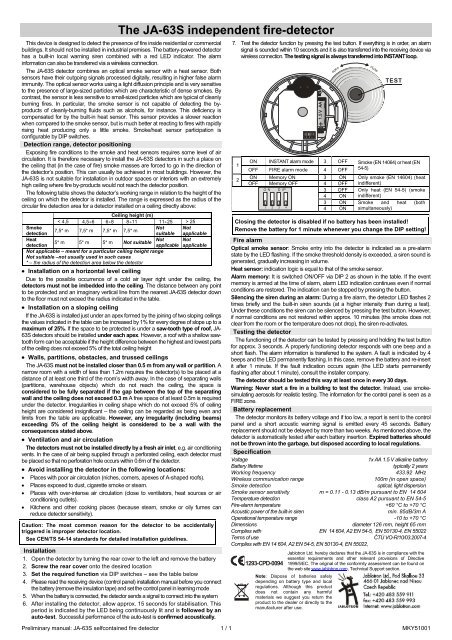
<strong>The</strong> <strong>JA</strong>-<strong>63S</strong> <strong>independent</strong> <strong>fire</strong>-<strong>detector</strong>This device is designed to detect the presence of <strong>fire</strong> inside residential or commercialbuildings. It should not be installed in industrial premises. <strong>The</strong> battery-powered <strong>detector</strong>has a built-in local warning siren combined with a red LED indicator. <strong>The</strong> alarminformation can also be transferred via a wireless connection.<strong>The</strong> <strong>JA</strong>-<strong>63S</strong> <strong>detector</strong> combines an optical smoke sensor with a heat sensor. Bothsensors have their outgoing signals processed digitally, resulting in higher false alarmimmunity. <strong>The</strong> optical sensor works using a light diffusion principle and is very sensitiveto the presence of large-sized particles which are characteristic of dense smokes. Bycontrast, the sensor is less sensitive to small-sized particles which are typical of cleanlyburning <strong>fire</strong>s. In particular, the smoke sensor is not capable of detecting the byproductsof cleanly-burning fluids such as alcohols, for instance. This deficiency iscompensated for by the built-in heat sensor. This sensor provides a slower reactionwhen compared to the smoke sensor, but is much better at reacting to <strong>fire</strong>s with rapidlyrising heat producing only a little smoke. Smoke/heat sensor participation isconfigurable by DIP switches.Detection range, <strong>detector</strong> positioningExposing <strong>fire</strong> conditions to the smoke and heat sensors requires some level of aircirculation. It is therefore necessary to install the <strong>JA</strong>-<strong>63S</strong> <strong>detector</strong>s in such a place onthe ceiling that (in the case of <strong>fire</strong>) smoke masses are forced to go in the direction ofthe <strong>detector</strong>’s position. This can usually be achieved in most buildings. However, the<strong>JA</strong>-<strong>63S</strong> is not suitable for installation in outdoor spaces or interiors with an extremelyhigh ceiling where <strong>fire</strong> by-products would not reach the <strong>detector</strong> position.<strong>The</strong> following table shows the <strong>detector</strong>’s working range in relation to the height of theceiling on which the <strong>detector</strong> is installed. <strong>The</strong> range is expressed as the radius of thecircular <strong>fire</strong> detection area for a <strong>detector</strong> installed on a ceiling directly above:Ceiling height (m)< 4,5 4,5÷6 6÷8 8÷11 11÷25 > 25SmokeNot Not7,5* m 7,5* m 7,5* m 7,5* mdetectionsuitable applicableHeatNot Not5* m 5* m 5* m Not suitabledetectionapplicable applicableNot applicable – meant for a particular ceiling height rangeNot suitable –not usually used in such cases* – the radius of the detection area below the <strong>detector</strong>• Installation on a horizontal level ceilingDue to the possible occurrence of a cold air layer right under the ceiling, the<strong>detector</strong>s must not be imbedded into the ceiling. <strong>The</strong> distance between any pointto be protected and an imaginary vertical line from the nearest <strong>JA</strong>-<strong>63S</strong> <strong>detector</strong> downto the floor must not exceed the radius indicated in the table.• Installation on a sloping ceilingIf the <strong>JA</strong>-<strong>63S</strong> is installed just under an apex formed by the joining of two sloping ceilingsthe values indicated in the table can be increased by 1% for every degree of slope up to amaximum of 25%. If the space to be protected is under a saw-tooth type of roof, <strong>JA</strong>-<strong>63S</strong> <strong>detector</strong>s should be installed under each apex. However, a roof with a shallow sawtoothform can be acceptable if the height difference between the highest and lowest partsof the ceiling does not exceed 5% of the total ceiling height• Walls, partitions, obstacles, and trussed ceilings<strong>The</strong> <strong>JA</strong>-<strong>63S</strong> must not be installed closer than 0.5 m from any wall or partition. Anarrow room with a width of less than 1.2m requires the <strong>detector</strong>(s) to be placed at adistance of at least one third of the room’s width away. In the case of separating walls(partitions, warehouse objects) which do not reach the ceiling, the space isconsidered to be fully separated if the gap between the top of the separatingwall and the ceiling does not exceed 0.3 m A free space of at least 0.5m is requiredunder the <strong>detector</strong>. Irregularities in ceiling shape which do not exceed 5% of ceilingheight are considered insignificant – the ceiling can be regarded as being even andlimits from the table are applicable. However, any irregularity (including beams)exceeding 5% of the ceiling height is considered to be a wall with theconsequences stated above.• Ventilation and air circulation<strong>The</strong> <strong>detector</strong>s must not be installed directly by a fresh air inlet, e.g. air conditioningvents. In the case of air being supplied through a perforated ceiling, each <strong>detector</strong> mustbe placed so that no perforation hole occurs within 0.6m of the <strong>detector</strong>.• Avoid installing the <strong>detector</strong> in the following locations:• Places with poor air circulation (niches, corners, apexes of A-shaped roofs).• Places exposed to dust, cigarette smoke or steam.• Places with over-intense air circulation (close to ventilators, heat sources or airconditioning outlets).• Kitchens and other cooking places (because steam, smoke or oily fumes canreduce <strong>detector</strong> sensitivity).Caution: <strong>The</strong> most common reason for the <strong>detector</strong> to be accidentallytriggered is improper <strong>detector</strong> location.See CEN/TS 54-14 standards for detailed installation guidelines.Installation1. Open the <strong>detector</strong> by turning the rear cover to the left and remove the battery2. Screw the rear cover onto the desired location3. Set the required function via DIP switches – see the table below4. Please read the receiving device (control panel) installation manual before you connectthe battery (remove the insulation tape) and set the control panel in learning mode5. When the battery is connected, the <strong>detector</strong> sends a signal to connect into the system6. After installing the <strong>detector</strong>, allow approx. 15 seconds for stabilisation. Thisperiod is indicated by the LED being continuously lit and is followed by anauto-test. Successful performance of the auto-test is confirmed acoustically.7. Test the <strong>detector</strong> function by pressing the test button. If everything is in order, an alarmsignal is sounded within 10 seconds and it is also transferred into the receiving device viawireless connection. <strong>The</strong> testing signal is always transferred into INSTANT loop.Preliminary manual: <strong>JA</strong>-<strong>63S</strong> selfcontained <strong>fire</strong> <strong>detector</strong> 1 / 1 MKY5100112+1.5 V AAopenON INSTANT alarm mode 3 OFFOFF FIRE alarm mode 4 OFFON Memory ON 3 ONOFF Memory OFF 4 OFFON DIP3 OFF4 ON3 ON1 2 4 34 ONcloseTESTSmoke (EN 14064) or heat (EN54-5)Only smoke (EN 14604) (heatindifferent)Only heat (EN 54-5) (smokeindifferent)Smoke and heat (bothsimultaneously)Closing the <strong>detector</strong> is disabled if no battery has been installed!Remove the battery for 1 minute whenever you change the DIP setting!Fire alarmOptical smoke sensor: Smoke entry into the <strong>detector</strong> is indicated as a pre-alarmstate by the LED flashing. If the smoke threshold density is exceeded, a siren sound isgenerated, gradually increasing in volume.Heat sensor: indication logic is equal to that of the smoke sensor.Alarm memory: It is switched ON/OFF via DIP 2 as shown in the table. If the eventmemory is armed at the time of alarm, alarm LED indication continues even if normalconditions are restored. <strong>The</strong> indication can be stopped by pressing the button.Silencing the siren during an alarm: During a <strong>fire</strong> alarm, the <strong>detector</strong> LED flashes 2times briefly and the built-in siren sounds (at a higher intensity than during a test).Under these conditions the siren can be silenced by pressing the test button. However,if normal conditions are not restored within approx. 10 minutes (the smoke does notclear from the room or the temperature does not drop), the siren re-activates.Testing the <strong>detector</strong><strong>The</strong> functioning of the <strong>detector</strong> can be tested by pressing and holding the test buttonfor approx. 3 seconds. A properly functioning <strong>detector</strong> responds with one beep and ashort flash. <strong>The</strong> alarm information is transferred to the system. A fault is indicated by 4beeps and the LED permanently flashing. In this case, remove the battery and re-insertit after 1 minute. If the fault indication occurs again (the LED starts permanentlyflashing after about 1 minute), consult the installer company.<strong>The</strong> <strong>detector</strong> should be tested this way at least once in every 30 days.Warning: Never start a <strong>fire</strong> in a building to test the <strong>detector</strong>. Instead, use smokesimulatingaerosols for realistic testing. <strong>The</strong> information for the control panel is seen as aFIRE zone.Battery replacement<strong>The</strong> <strong>detector</strong> monitors its battery voltage and if too low, a report is sent to the controlpanel and a short acoustic warning signal is emitted every 45 seconds. Batteryreplacement should not be delayed by more than two weeks. As mentioned above, the<strong>detector</strong> is automatically tested after each battery insertion. Expired batteries shouldnot be thrown into the garbage, but disposed according to local regulations.SpecificationVoltage1x AA 1.5 V alkaline batteryBattery lifetimetypically 2 yearsWorking frequency433.92 MHzWireless communication range100m (in open space)Smoke detectionoptical, light dispersionSmoke sensor sensitivity m = 0.11 - 0.13 dB/m pursuant to EN 14 604Temperature detection class A2 pursuant to EN 54-5Fire-alarm temperature +60 °C to +70 °CAcoustic power of the built-in sirenmin. 85dB/3m AOperational temperature range -10 to +70 °CDimensionsdiameter 126 mm, height 65 mmComplies with EN 14 604, A2 EN 54-5, EN 50130-4, EN 55022Terms of useČTÚ VO-R/10/03.2007-4Complies with EN 14 604, A2 EN 54-5, EN 50130-4, EN 55022,Jablotron Ltd. hereby declares that the <strong>JA</strong>-<strong>63S</strong> is in compliance with theessential requirements and other relevant provisions of Directive1293-CPD-0094 1999/5/EC. <strong>The</strong> original of the conformity assessment can be found onthe web site www.jablotron.com, Technical Support section.Note: Dispose of batteries safelydepending on battery type and localregulations. Although this productdoes not contain any harmfulmaterials we suggest you return theproduct to the dealer or directly to themanufacturer after use.
Sample 2 / 2 mxx5yyzz