Biomechanical Principles - Univeristy of Oregon Biomechanics
Biomechanical Principles - Univeristy of Oregon Biomechanics
Biomechanical Principles - Univeristy of Oregon Biomechanics
- No tags were found...

Create successful ePaper yourself
Turn your PDF publications into a flip-book with our unique Google optimized e-Paper software.
Chapter 1 | INTRODUCTION TO BIOMECHANICAL ANALYSIS7components represent the magnitude <strong>of</strong> the vector in thatdirection. The x and y components are summed:SuperiorC X A X B X (Equation 2.7)C Y A Y B Y (Equation 2.8)The vector C can either be left in terms <strong>of</strong> its components,C X and C Y , or be converted into a magnitude, C, using thePythagorean theorem, and orientation, , using trigonometry.This method is the most efficient <strong>of</strong> the three presented andis used throughout the text.VECTOR MULTIPLICATIONFrontalSagittalMultiplication <strong>of</strong> a vector by a scalar is relatively straightforward.Essentially, each component <strong>of</strong> the vector is individuallymultiplied by the scalar, resulting in another vector. Forexample, if the vector in Figure 1.2 is multiplied by 5, the resultis A X 5 4 N 20 N and A Y 5 3 N 15 N.Another form <strong>of</strong> vector multiplication is the cross product,in which two vectors are multiplied together, resulting in anothervector (C A B). The orientation <strong>of</strong> C is such thatit is mutually perpendicular to A and B. The magnitude <strong>of</strong> Cis calculated as C A B sin (), where represents theangle between A and B, and denotes scalar multiplication.These relationships are illustrated in Figure 1.3. The crossproduct is used for calculating joint torques below in thischapter.PosteriorTransverseLateralMedialAnteriorCoordinate SystemsA three-dimensional analysis is necessary for a complete representation<strong>of</strong> human motion. Such analyses require a coordinatesystem, which is typically composed <strong>of</strong> anatomicallyaligned axes: medial/lateral (ML), anterior/posterior (AP), andsuperior/inferior (SI). It is <strong>of</strong>ten convenient to consider onlya two-dimensional, or planar, analysis, in which only two <strong>of</strong>the three axes are considered. In the human body, there arethree perpendicular anatomical planes, which are referred toas the cardinal planes. The sagittal plane is formed by theSI and AP axes, the frontal (or coronal) plane is formedby the SI and ML axes, and the transverse plane is formedby the AP and ML axes (Fig. 1.4).CMagnitude <strong>of</strong> C: C = ABsin(θ)Orientation <strong>of</strong> C: perpendicular toboth A and BBInferiorFigure 1.4: Cardinal planes. The cardinal planes, sagittal,frontal, and transverse, are useful reference frames in athree-dimensional representation <strong>of</strong> the body. In twodimensionalanalyses, the sagittal plane is the commonreference frame.θFigure 1.3: Vector cross product. C is shown as the cross product<strong>of</strong> A and B. Note that A and B could be any two vectors in theindicated plane and C would still have the same orientation.AThe motion <strong>of</strong> any bone can be referenced with respectto either a local or global coordinate system. For example,the motion <strong>of</strong> the tibia can be described by how it moveswith respect to the femur (local coordinate system) or how
8 Part I | BIOMECHANICAL PRINCIPLESit moves with respect to the room (global coordinate system).Local coordinate systems are useful for understandingjoint function and assessing range <strong>of</strong> motion, while globalcoordinate systems are useful when functional activities areconsidered.Most <strong>of</strong> this text focuses on two-dimensional analyses, forseveral reasons. First, it is difficult to display three-dimensionalinformation on the two-dimensional pages <strong>of</strong> a book. Additionally,the mathematical analysis for a three-dimensionalproblem is very complex. Perhaps the most important reasonis that the fundamental biomechanical principles in a twodimensionalanalysis are the same as those in a three-dimensionalanalysis. It is therefore possible to use a simplifiedtwo-dimensional representation <strong>of</strong> a three-dimensional problemto help explain a concept with minimal mathematicalcomplexity (or at least less complexity).F ABF AB - Abductor muscle forceF AD - Adductor muscle forceF JR - Joint reaction forceF GR - Ground reaction forceF JRF ADF GRFORCES AND MOMENTSThe musculoskeletal system is responsible for generatingforces that move the human body in space as well as preventunwanted motion. Understanding the mechanics and pathomechanics<strong>of</strong> human motion requires an ability to study theforces and moments applied to, and generated by, the bodyor a particular body segment.ForcesThe reader may have a conceptual idea about what a forceis but find it difficult to come up with a formal definition.For the purposes <strong>of</strong> this text, a force is defined as a “pushor pull” that results from physical contact between two objects.The only exception to this rule that is considered inthis text is the force due to gravity, in which there is no directphysical contact between two objects. Some <strong>of</strong> the more commonforce generators with respect to the musculoskeletalsystem include muscles/tendons, ligaments, friction, groundreaction, and weight.A distinction must be made between the mass and theweight <strong>of</strong> a body. The mass <strong>of</strong> an object is defined as theamount <strong>of</strong> matter composing that object. The weight <strong>of</strong> anobject is the force acting on that object due to gravity and isthe product <strong>of</strong> its mass and the acceleration due to gravity(g 9.8 m/s 2 ). So while an object’s mass is the same on Earthas it is on the moon, its weight on the moon is less, since theacceleration due to gravity is lower on the moon. This distinctionis important in biomechanics, not to help plan a tripto the moon, but for ensuring that a unit <strong>of</strong> mass is not treatedas a unit <strong>of</strong> force.As mentioned previously, force is a vector quantity withmagnitude, orientation, direction, and a point <strong>of</strong> application.Figure 1.5 depicts several forces acting on the leg in thefrontal plane during stance. The forces from the abductorand adductor muscles act through their tendinous insertions,Figure 1.5: Vectors in anatomy. Example <strong>of</strong> how vectors can becombined with anatomical detail to represent the action <strong>of</strong>forces. Some <strong>of</strong> the forces acting on the leg are shown here.while the hip joint reaction force acts through its respectivejoint center <strong>of</strong> rotation. In general, the point <strong>of</strong> application<strong>of</strong> a force (e.g., tendon insertion) is located with respect toa fixed point on a body, usually the joint center <strong>of</strong> rotation.This information is used to calculate the moment due tothat force.
Chapter 1 | INTRODUCTION TO BIOMECHANICAL ANALYSIS9FM = Frsin(θ)FRotationMrrθAFigure 1.6: Three-dimensional moment analysis. The momentacting on the elbow from the force <strong>of</strong> the biceps is shown asa vector aligned with the axis <strong>of</strong> rotation. F, force vector; r,distance from force vector to joint COR; M, moment vector.MomentsIn kinesiology, a moment (M) is typically caused by a force(F) acting at a distance (r) from the center <strong>of</strong> rotation <strong>of</strong> asegment. A moment tends to cause a rotation and is definedby the cross product function: M r F. Therefore, a momentis represented by a vector that passes through the point<strong>of</strong> interest (e.g., the center <strong>of</strong> rotation) and is perpendicularto both the force and distance vectors (Fig. 1.6). For a twodimensionalanalysis, both the force and distance vectors arein the plane <strong>of</strong> the paper, so the moment vector is always directedperpendicular to the page, with a line <strong>of</strong> action throughthe point <strong>of</strong> interest. Since it has only this one orientation andline <strong>of</strong> action, a moment is <strong>of</strong>ten treated as a scalar quantityin a two-dimensional analysis, with only magnitude anddirection. Torque is another term that is synonymous with ascalar moment. From the definition <strong>of</strong> a cross product, themagnitude <strong>of</strong> a moment (or torque) is calculated as M r F sin (). Its direction is referred to as the direction inwhich it would tend to cause an object to rotate (Fig. 1.7A).Although there are several different distances that can beused to connect a vector and a point, the same moment iscalculated no matter which distance is selected (Fig. 1.7B).M = Fr 1 sin(θ 1 )M = Fr 2 sin(θ 2 ) = F * MAFM = Fr 3 sin(θ 3 )M = Fr 4 sin(θ 4 )θ 1r 1 r 1θ 2 r 2θ 3 r 3r 4θ 4BFigure 1.7: Continued
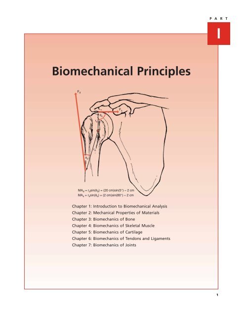
10 Part I | BIOMECHANICAL PRINCIPLESA. Idealized⎺F 1⎺F 1⎺F 2d⎺F 1 = ⎺F - 2CORd⎺F 2Fsin(θ 1 ) = sin(θ 3 )= sin(180° – θ 1 ) = sin(θ 2 )= sin(180° – θ 1 ) = sin(θ 4 )r 1θr 1θ 2θ 4θ 3B. ActualCORUpper trapezius⎺F 1 ≠⎺F - 2Serratus anteriorCFigure 1.7: Two-dimensional moment analysis. A. Plantar flexionmoment created by force at the Achilles tendon. B. Note thatno matter which distance vector is chosen, the value for themoment is the same. C. Also, no matter which angle is chosen,the value for the sine <strong>of</strong> the angle is the same, so the momentis the same.The distance that is perpendicular to the force vector is referredto as the moment arm (MA) <strong>of</strong> that force (r 2 in Fig.1.7B). Since the sine <strong>of</strong> 90° is equal to 1, the use <strong>of</strong> a momentarm simplifies the calculation <strong>of</strong> moment to M MA F.The moment arm can also be calculated from any distance asMA r sin (). Additionally, although there are four separateangles between the force and distance vectors, all fourangles result in the same moment calculation (Fig. 1.7C).The examples in Figures 1.6 and 1.7 have both force andmoment components. However, consider the situation inFigure 1.8A. Although the two applied forces create amoment, they have the same magnitude and orientation butopposite directions. Therefore, their vector sum is zero. Thisis an example <strong>of</strong> a force couple. A pure force couple resultsin rotational motion only, since there are no unbalancedforces. In the musculoskeletal system, all <strong>of</strong> these conditionsare seldom met, so pure force couples are rare. In general,muscles are responsible for producing both forces and moments,thus resulting in both translational and rotationalFigure 1.8: Force couples. Distinction between an idealized forcecouple (A) and a more realistic one (B). Even though thescapular example given is not a true force couple, it is typicallyreferred to as one. COR, center <strong>of</strong> rotation.motion. However, there are examples in the human body inwhich two or more muscles work in concert to produce a moment,such as the upper trapezius and serratus anterior (Fig.1.8B). Although these muscles do not have identical magnitudesor orientations, this situation is frequently referred toas a force couple.Muscle ForcesAs mentioned previously, there are three important parametersto consider with respect to the force <strong>of</strong> a muscle: orientation,magnitude, and point <strong>of</strong> application. With some care,it is possible to measure orientation and line <strong>of</strong> action fromcadavers or imaging techniques such as magnetic resonanceimaging (MRI) and computed tomography (CT) [1,3]. This informationis helpful in determining the function and efficiency<strong>of</strong> a muscle in producing a moment. As an example, two musclesthat span the glenohumeral joint, the supraspinatus andmiddle deltoid, are shown in Box 1.2. From the informationprovided for muscle orientation and point <strong>of</strong> application in thisposition, the moment arm <strong>of</strong> the deltoid is approximately equalto that <strong>of</strong> the supraspinatus, even though the deltoid insertionon the humerus is much farther away from the center <strong>of</strong>rotation than the supraspinatus insertion.
Chapter 1 | INTRODUCTION TO BIOMECHANICAL ANALYSIS11EXAMINING THE FORCES BOX 1.2MOMENT ARMS OF THE DELTOID (MA d ) ANDTHE SUPRASPINATUS (MA s )many simplifying assumptions, such methods can be very usefulin understanding joint mechanics, and they are presentedin the next section.STATICSF dθ sF sr sStatics is the study <strong>of</strong> the forces acting on a body at rest ormoving with a constant velocity. Although the human body isalmost always accelerating, a static analysis <strong>of</strong>fers a simplemethod <strong>of</strong> addressing musculoskeletal problems. This analysismay either solve the problem or provide a basis for a moresophisticated dynamic analysis.Newton’s Lawsθ dr dMA d = r d sin(θ d ) = (20 cm)sin(5°) ≈ 2 cmMA s = r s sin(θ s ) = (2 cm)sin(80°) ≈ 2 cmCLINICAL RELEVANCE: MUSCLE FORCESIn addition to generating moments that are responsiblefor angular motion (rotation), muscles also produce forcesthat can cause linear motion (translation). This force canbe either a stabilizing or a destabilizing force. For example,since the supraspinatus orientation shown in Box 1.2is primarily directed medially, it tends to pull the humeralhead into the glenoid fossa. This compressive force helpsstabilize the glenohumeral joint. However, since the deltoidorientation is directed superiorly, it tends to producea destabilizing force that may result in superior translation<strong>of</strong> the humeral head.These analyses are useful, since they can be performed evenif the magnitude <strong>of</strong> a muscle’s force is unknown. However, tounderstand a muscle’s function completely, its force magnitudemust be known. Although forces can be measured withinvasive force transducers [12], instrumented arthroplastysystems [6], or simulations in cadaver models [9], there arecurrently no noninvasive experimental methods that can beused to measure the in vivo force <strong>of</strong> intact muscles. Consequently,basic concepts borrowed from freshman physics canbe used to predict muscle forces. Although they <strong>of</strong>ten involveSince the musculoskeletal system is simply a series <strong>of</strong> objectsin contact with each other, some <strong>of</strong> the basic physics principlesdeveloped by Sir Isaac Newton (1642–1727) are useful.Newton’s laws are as follows:First law: An object remains at rest (or continues movingat a constant velocity) unless acted upon by an unbalancedexternal force.Second law: If there is an unbalanced force acting on aobject, it produces an acceleration in the direction <strong>of</strong>the force, directly proportional to the force (f ma).Third law: For every action (force) there is a reaction(opposing force) <strong>of</strong> equal magnitude but in the oppositedirection.From the first law, it is clear that if a body is at rest, therecan be no unbalanced external forces acting on it. In this situation,termed static equilibrium, all <strong>of</strong> the external forcesacting on a body must add (in a vector sense) to zero. An extension<strong>of</strong> this law to objects larger than a particle is that thesum <strong>of</strong> the external moments acting on that body must alsobe equal to zero for the body to be at rest. Therefore, for athree-dimensional analysis, there are a total <strong>of</strong> six equationsthat must be satisfied for static equilibrium:F X 0 F Y 0 F Z 0M X 0 M Y 0 M Z 0 (Equation 2.9)For a two-dimensional analysis, there are only two in-planeforce components and one perpendicular moment (torque)component:F X 0 F Y 0 M Z 0 (Equation 2.10)Under many conditions, it is reasonable to assume that allbody parts are in a state <strong>of</strong> static equilibrium and thesethree equations can be used to calculate some <strong>of</strong> the forcesacting on the musculoskeletal system. When a body is not instatic equilibrium, Newton’s second law states that anyunbalanced forces and moments are proportional to theacceleration <strong>of</strong> the body. That situation is considered laterin this chapter.
12 Part I | BIOMECHANICAL PRINCIPLESSolving ProblemsA general approach used to solve for forces during static equilibriumis as follows:Step 1 Isolate the body <strong>of</strong> interest.Step 2 Sketch this body and all external forces(referred to as a free body diagram).Step 3 Sum the forces and moments equal to zero.Step 4 Solve for the unknown forces.As a simple example, consider the two 1-kg balls hangingfrom strings shown in Box 1.3. What is the force acting onthe top string? Although this is a very simple problem thatcan be solved by inspection, a formal analysis is presented.Step 1 is to sketch the entire system and then place a dottedbox around the body <strong>of</strong> interest. Consider a box that encompassesboth balls and part <strong>of</strong> the string above the top one, asshown in Box 1.3.Proceeding to step 2, a free body diagram is sketched. Asindicated by Newton’s first law, only external forces are consideredfor these analyses. For this example, everything insidethe dotted box is considered part <strong>of</strong> the body <strong>of</strong> interest.External forces are caused by the contact <strong>of</strong> two objects, oneinside the box and one outside the box. In this example, thereare three external forces: tension in the top string and theweight <strong>of</strong> each <strong>of</strong> the balls.Why is the tension on the top string considered an externalforce, but not the force on the bottom string? The reasonis that the tension on the top string is an external force (part<strong>of</strong> the string is in the box and part is outside the box), andthe force on the bottom string is an internal force (the entirestring is located inside the box). This is a very important distinctionbecause it allows for isolation <strong>of</strong> the forces on specificmuscles or joints in the musculoskeletal system.EXAMINING THE FORCES BOX 1.3A FREE BODY DIAGRAMyx1 Kg1 KgΣF y = 0T – F – F = 0T = 2F = 2 (10 N)T = 20 NFree body diagramFFWTF = mg = (1 kg)(9.8 m )s 2=10 NWhy is the weight <strong>of</strong> each ball considered an externalforce? Although gravity is not caused by contact between twoobjects, it is caused by the interaction <strong>of</strong> two objects and istreated in the same manner as a contact force. One <strong>of</strong> the objectsis inside the box (the ball) and the other is outside thebox (the Earth). In general, as long as an object is locatedwithin the box, the force <strong>of</strong> gravity acting on it should beconsidered an external force.Why is the weight <strong>of</strong> the string not considered an externalforce? To find an exact answer to the problem, it should beconsidered. However, since its weight is far less than that <strong>of</strong>the balls, it is considered negligible. In biomechanical analyses,assumptions are <strong>of</strong>ten made to ignore certain forces, suchas the weight <strong>of</strong> someone’s watch during lifting.Once all the forces are in place, step 3 is to sum all theforces and moments equal to zero. There are no forces inthe x direction, and since all <strong>of</strong> the forces pass through thesame point, there are no moments to consider. That leavesonly one equation: sum <strong>of</strong> the forces in the y direction equalto zero. The fourth and final step is to solve for the unknownforce. The mass <strong>of</strong> the balls is converted to force by multiplyingby the acceleration <strong>of</strong> gravity. The complete analysis isshown in Box 1.3.Simple Musculoskeletal ProblemsAlthough most problems can be addressed with the aboveapproach, there are special situations in which a problem issimplified. These may be useful both for solving problems analyticallyand for quick assessment <strong>of</strong> clinical problems froma biomechanical perspective.LINEAR FORCESThe simplest type <strong>of</strong> system, linear forces, consists <strong>of</strong> forceswith the same orientation and line <strong>of</strong> action. The only thingsthat can be varied are the force magnitudes and directions.An example is provided in Box 1.3. Notice that the only equationneeded is summing the forces along the y axis equal tozero. When dealing with linear forces, it is best to align eitherthe x or y axis with the orientation <strong>of</strong> the forces.PARALLEL FORCESA slightly more complicated system is one in which all theforces have the same orientation but not the same line <strong>of</strong> action.In other words, the force vectors all run parallel to eachother. In this situation, there are still only forces along oneaxis, but there are moments to consider as well.LeversA lever is an example <strong>of</strong> a parallel force system that is verycommon in the musculoskeletal system. Although not alllevers contain parallel forces, that specific case is focused onhere. A basic understanding <strong>of</strong> this concept allows for a rudimentaryanalysis <strong>of</strong> a biomechanical problem with very littlemathematics.
Chapter 1 | INTRODUCTION TO BIOMECHANICAL ANALYSISA lever consists <strong>of</strong> a rigid body with two externally appliedforces and a point <strong>of</strong> rotation. In general, for the musculoskeletaljoint, one <strong>of</strong> the forces is produced by a muscle,one force is provided by contact with the environment (or bygravity) and the point <strong>of</strong> rotation is the center <strong>of</strong> rotation <strong>of</strong>the joint. The two forces can either be on the same side ordifferent sides <strong>of</strong> the center <strong>of</strong> rotation (COR).If the forces are on different sides <strong>of</strong> the COR, the systemis considered a first class lever. If the forces are on the sameside <strong>of</strong> the COR and the external force is closer to the CORthan the muscle force, it is a second class lever. If the forcesare on the same side <strong>of</strong> the COR and the muscle force iscloser to the COR than the external force, it is a third classlever. There are several cases <strong>of</strong> first class levers; however,most joints in the human body behave as third class levers.Second class levers are almost never observed within the body.Examples <strong>of</strong> all three levers are given in Figure 1.9.13If moments are summed about the COR for any lever, theresistive force is equal to the muscle force times the ratio <strong>of</strong>the muscle and resistive moment arms:F R F M (MA M MA R ) (Equation 2.11)The ratio <strong>of</strong> the muscle and resistive moment arms(MA M MA R ) is referred to as the mechanical advantage<strong>of</strong> the lever. Based on this equation and the definition <strong>of</strong>levers, the mechanical advantage is greater than one for asecond class lever, less than one for a third class lever, andeither for a first class lever. A consequence <strong>of</strong> this is that sincemost joints behave as third class levers, muscle forces mustalways be greater than the force <strong>of</strong> the resistive load they areopposing. Although this may appear to represent an inefficientdesign, muscles sacrifice their mechanical advantageto produce large motions and high-velocity motions. Thisequation is also valid in cases where the two forces are notFRCORFAFCORCORBRCRFigure 1.9: Classification <strong>of</strong> lever systems. Examples <strong>of</strong> the three different classes <strong>of</strong> levers, where F is the exerted force, R is thereaction force, and COR is the center <strong>of</strong> rotation. Most musculoskeletal joints behave as third class levers. A. First class lever.B. Second class lever. C. Third class lever.
Chapter 1 | INTRODUCTION TO BIOMECHANICAL ANALYSIS15TABLE 1.2 Body Segment Parameters Derived from Dempster [4]Location <strong>of</strong> the Center <strong>of</strong>Moment <strong>of</strong> InertiaPercentage <strong>of</strong> Total Mass (% <strong>of</strong> limb segment about the Center <strong>of</strong>Body Weight (%) length from proximal end) Mass (kg m 2 )Head and neck 7.9 43.3 0.029Trunk 48.6 n.a. n.a.Upper extremity 4.9 51.2 a 0.335Arm 2.7 43.6 0.040Forearm and hand 2.2 67.7 0.058Forearm 1.6 43.0 0.018Hand 0.6 50.6 b 0.002Lower extremity 15.7 43.4 c 1.785Thigh 9.6 43.3 0.298Leg and foot 5.9 43.3 0.339Leg 4.5 43.4 0.143Foot 1.4 43.8 d 0.007a Measured from axis <strong>of</strong> shoulder to ulnar styloid process.b Measured to PIP joint <strong>of</strong> long finger.c Measured to medial malleolus.d Measured from heel.FORCE ANALYSIS WITH A SINGLE MUSCLEThere are additional assumptions that are typically made tosolve for a single muscle force:• Two-dimensional analysis• No deformation <strong>of</strong> any tissues• No friction in the system• The single muscle force that has been selected can be concentratedin a single line <strong>of</strong> action• No accelerationThe glenohumeral joint shown in Box 1.2 is used as anexample to help demonstrate the general strategy for approachingthese problems. Since only one muscle force canbe considered, the supraspinatus is chosen for analysis. Thesame general approach introduced earlier in this chapter foraddressing a system in static equilibrium is used.Step one is to isolate the body <strong>of</strong> interest, which for thisproblem is the humerus. In step two, a free body diagramis drawn, with all <strong>of</strong> the external forces clearly labeled: theweight <strong>of</strong> the arm (F G ), the supraspinatus force (F S ), andthe glenohumeral joint reaction force (F J ) in Box 1.4. Notethat external objects like the scapula are <strong>of</strong>ten included inthe free body diagram to make the diagram complete. However,the scapula is external to the analysis and is only includedfor convenience. It is important to keep track <strong>of</strong>which objects are internal and which ones are external tothe isolated body.The next step is to sum the forces and moments to zeroto solve for the unknown values. Since the joint reaction forceacts through the COR, a good strategy is to start by summingthe moments to zero at that point. This effectively eliminatesEXAMINING THE FORCES BOX 1.4STATIC EQUILIBRIUM EQUATIONSCONSIDERING ONLY THE SUPRASPINATUSΣM = 0 (at COR)(F S )(R S )sin(90°) – (F G )(R G )sin(30°) = 0FS = (28N)(29 cm)sin 30° = 203 N2 cmΣF X = 0F S +F JX = 0F JX =-F S = -203 NΣF Y = 0-F G +F JY = 0 R S = 2 cmF JY =F G = 28 NR G = 29 cmF G = 28 N30°CORF JF S
16 Part I | BIOMECHANICAL PRINCIPLESthe joint reaction force from this equation because its momentarm is equal to zero. The forces along the x and y axesare summed to zero to find those components <strong>of</strong> the joint reactionforce. The fourth and final step is to solve for the unknownparameters in these three equations. The details <strong>of</strong>these calculations are given in Box 1.4. In this example, themagnitude <strong>of</strong> the supraspinatus force is 203 N, and the jointreaction force is 203 N lateral and 28 N superior. Those componentsrepresent the force <strong>of</strong> the scapula acting on thehumerus. Newton’s third law can then be used to find theforce <strong>of</strong> the humerus acting on the scapula: 203 N medial and28 N inferior.Note that the muscle force is much larger than the weight<strong>of</strong> the arm. This is expected, considering the small momentarm <strong>of</strong> the muscle compared with the moment arm <strong>of</strong> theforce due to gravity. While this puts muscles at a mechanicaldisadvantage for force production, it enables them to amplifytheir motion. For example, a 1-cm contraction <strong>of</strong> thesupraspinatus results in a 20-cm motion at the hand. This isdiscussed in more detail in Chapter 4.STATIC EQUILIBRIUM EQUATIONSCONSIDERING ONLY THE DELTOID MUSCLEYEXAMINING THE FORCES BOX 1.5F DXR D = 20 cm5°F G = 28N30°R G = 29 cmCORF JΣM = 0 (at COR)(F D )(R D )sin(5°) – (F G )(R G )sin(30°) = 0F D = (28 N)(29 cm)sin(30°) = 233 N(20 cm)sin(5°)ΣF X = 0F D cos(35°)+F JX = 0F JX = -233cos(35°) = -191 NΣF Y = 0-F G +F JY + F D sin(40°)= 0F JY = 28 – 233sin(40°) = -106 NThe problem can be solved again by considering the middledeltoid instead <strong>of</strong> the supraspinatus. For those conditions,Box 1.5 shows that the deltoid muscle force is 233 N and theforce <strong>of</strong> the humerus acting on the scapula is 191 N medialand 106 N superior. Notice that although the force required<strong>of</strong> each muscle is similar (supraspinatus, 203 N vs. deltoid,230 N), the deltoid generates a much higher superior forceand the supraspinatus generates a much higher medial force.CLINICAL RELEVANCE: SUPRASPINATUS ANDDELTOID MUSCLE FORCESA clinical application <strong>of</strong> these results is that under normalconditions the supraspinatus serves to maintain joint stabilitywith its medially directed force. However, if itsintegrity is compromised, as occurs with rotator cuff disease,and the deltoid plays a larger role, then there is alower medial stabilizing force and a higher superior forcethat may cause impingement <strong>of</strong> the rotator cuff in the subacromialregion.The analysis presented above serves as a model for analyzingmuscle and joint reaction forces in subsequent chapters.Although some aspects <strong>of</strong> the problem will clearly vary fromjoint to joint, the basic underlying method is the same.FORCE ANALYSIS WITH MULTIPLE MUSCLESAlthough most problems addressed in this text focus on solvingfor muscle forces when only one muscle is taken into consideration,it would be advantageous to solve problems inwhich there is more than one muscle active. However suchsystems are statically indeterminate. Additional informationis needed regarding the relative contribution <strong>of</strong> each muscleto develop an appropriate solution.One method for analyzing indeterminate systems is theoptimization method. Since an indeterminate system allowsan infinite number <strong>of</strong> solutions, the optimization approachhelps select the “best” solution. An optimizationmodel minimizes some cost function to produce a single solution.This function may be the total force in all <strong>of</strong> themuscles or possibly the total stress (force/area) in all <strong>of</strong> themuscles. While it might make sense that the central nervoussystem attempts to minimize the work it has to do to performa function, competing demands <strong>of</strong> a joint must also bemet. For example, in the glenohumeral example above, itmight be most efficient from a force production standpointto assume that the deltoid acts alone. However, from astability standpoint, the contribution <strong>of</strong> the rotator cuff isessential.Another method for analyzing indeterminate systems is thereductionist model in which a set <strong>of</strong> rules is applied for therelative distribution <strong>of</strong> muscle forces based on electromyographic(EMG) signals. One approach involves developingthese rules on the basis <strong>of</strong> the investigator’s subjective knowledge<strong>of</strong> EMG activity, anatomy, and physiological constraints
Chapter 1 | INTRODUCTION TO BIOMECHANICAL ANALYSIS[4]. Another approach is to have subjects perform isometriccontractions at different force levels while measuring EMGsignals and to develop an empirical relationship betweenEMG and force level [2,7]. Perhaps the most commonapproach is based on the assumption that muscle force is proportionalto its cross-sectional area and EMG level. Thismethod has been attempted for many joints, such as theshoulder [10], knee and hip. One <strong>of</strong> the key assumptions inall these approaches is that there is a known relationshipbetween EMG levels and force production.KINEMATICS17same. Similarly, the translational component <strong>of</strong> this motioncan be measured by tracking the change in position <strong>of</strong> a pointon the bone. In this case, however, the amount <strong>of</strong> translatorymotion is not the same for all points. In fact, the displacement<strong>of</strong> a point increases linearly as its distance from theCOR increases (Fig. 1.11B). Therefore, from a practicalstandpoint, if there is any rotation <strong>of</strong> a bone, a description<strong>of</strong> joint translation or displacement must refer to a specificpoint on the bone.Consider the superior/inferior translation motion <strong>of</strong> thehumerus in Figure 1.12A, which is rotated 90°. Point 1 representsthe geometric center <strong>of</strong> the humeral head and doesUntil now, the focus has been on studying the static forcesacting on the musculoskeletal system. The next section dealswith kinematics, which is defined as the study <strong>of</strong> motionwithout regard to the forces that cause that motion. As withthe static force analysis, this section is restricted to twodimensional,or planar, motion.A1 22'Rotational and Translational MotionPure linear, or translatory, motion <strong>of</strong> an entire object occurswhen all points on that object move the same distance(Fig. 1.11A). However, with the possible exception <strong>of</strong> passivemanipulation <strong>of</strong> joints, pure translatory motion does not<strong>of</strong>ten occur at musculoskeletal articulations. Instead, rotationalmotion is more common, in which there is one pointon a bone that remains stationary (the COR), and all otherpoints trace arcs <strong>of</strong> a circle around this point (Fig. 1.11B).For three-dimensional motion, the COR would be replacedby an axis <strong>of</strong> rotation, and there could also be translationalong this axis.Consider the general motion <strong>of</strong> a bone moving from aninitial to a final position. The rotational component <strong>of</strong> thismotion can be measured by tracking the change in orientation<strong>of</strong> a line on the bone. Although there are an infinitenumber <strong>of</strong> lines to choose from, it turns out that no matterwhich line is selected, the amount <strong>of</strong> rotation is always theBSI Translation1 - None2 - InferiorSI Translation1 - Superior2 - InferiorP 2P 11'P 122'P 12CORABFigure 1.11: Translations and rotations. In biomechanics, motionis typically described in terms <strong>of</strong> translations and rotations.A. In translatory motion, all points on the object move thesame distance. B. In rotational motion, all points on the objectrevolve around the center <strong>of</strong> rotation (COR), which is fixedin space.Figure 1.12: Translations and rotations within a joint. For both<strong>of</strong> these examples, it is fairly straightforward to describe therotational motion <strong>of</strong> the humerus—it rotates 90°. However,translational motion is more complicated, and it is important torefer to a specific point. Consider the superior/inferior (SI)translation <strong>of</strong> two points: point 1 is located at the center <strong>of</strong> thehumeral head and point 2 sits closer to the articular surface.A. The center <strong>of</strong> the rotation <strong>of</strong> the motion is at point 1,so there is no translation at point 1, but point 2 movesinferiorly. B. Point 1 moves superiorly, and point 2 movesinferiorly.
18 Part I | BIOMECHANICAL PRINCIPLESnot translate from position 1 to 2. However, point 2 on thearticular surface <strong>of</strong> the humeral head translates inferiorly. Themotion in Figure 1.12B is similar, except now point 1 translatessuperiorly, while point 2 still translates inferiorly. Thisexample demonstrates how important the point <strong>of</strong> referenceis when describing joint translations.Displacement, Velocity,and AccelerationBoth linear and angular displacements are measures <strong>of</strong> distance.Position is defined as the location <strong>of</strong> a point or objectin space. Displacement is defined as the distance traveledbetween two locations. For example, consider the knee jointduring gait. If its angular position is 10° <strong>of</strong> flexion at heelstrike and 70° <strong>of</strong> flexion at toe <strong>of</strong>f, the angular displacementfrom heel strike to toe <strong>of</strong>f is 60° <strong>of</strong> flexion.Change in linear and angular position (displacement) overtime is defined as linear and angular velocity, respectively.Finding the instantaneous velocity at any given point in time,requires the use <strong>of</strong> calculus. Instantaneous velocity is definedas the differential <strong>of</strong> position with respect to time. Averagevelocity may be calculated by simply considering two separatelocations <strong>of</strong> an object and taking the change its positionand dividing by the change in time (Table 1.3). As the timeinterval becomes smaller and approaches zero, the averagevelocity approaches the instantaneous velocity.Similarly, changes in linear and angular velocity over timeare defined as linear and angular acceleration. Instantaneousacceleration is defined as the differential <strong>of</strong> velocity withrespect to time. Average acceleration may be calculated bysimply considering two separate locations <strong>of</strong> an object andtaking the change in its velocity and dividing by the changein time (Table 1.3). An example <strong>of</strong> the effect <strong>of</strong> constant accelerationon velocity and position is shown in Figure 1.13.KINETICSUntil now, forces and motion have been discussed as separatetopics. Kinetics is the study <strong>of</strong> motion under the action<strong>of</strong> forces. This is a very complex topic that is only introducedhere to give the reader some working definitions. The onlychapter in this text that deals with these terms in any detailis Chapter 48 on gait analysis.Inertial ForcesKinematics and kinetics are bound by Newton’s second law,which states that the external force (f) on an object is proportionalto the product <strong>of</strong> that object’s mass (m) and linearacceleration (a):f ma (Equation 2.12)For conditions <strong>of</strong> static equilibrium, there are no externalforces because there is no acceleration, and the sum <strong>of</strong> theexternal forces can be set equal to zero. However, when anobject is accelerating, the so-called inertial forces (due toacceleration) must be considered, and the sum <strong>of</strong> the forcesis no longer equal to zero.Consider a simple example <strong>of</strong> a linear force system inwhich someone is trying to pick up a 20-kg box. If this is performedvery slowly so that the acceleration is negligible, staticequilibrium conditions can be applied (sum <strong>of</strong> forces equalzero), and the force required is 200 N (Box 1.6). However, ifthis same box is lifted with an acceleration <strong>of</strong> 5 m/s 2 , then thesum <strong>of</strong> the forces is not equal to zero, and the force requiredis 300 N (Box 1.6).There is an analogous relationship for rotational motion,in which the external moment (M) on an object is proportionalto that object’s moment <strong>of</strong> inertia (I) and angular acceleration():M I (Equation 2.13)Just as mass is a measure <strong>of</strong> a resistance to linear acceleration,moment <strong>of</strong> inertia is a measure <strong>of</strong> resistance to angularacceleration (Table 1.2). It is affected both by the total massand the distance that mass is from the COR, r, as follows:I mr 2 (Equation 2.14)So the farther the mass <strong>of</strong> an object is from the COR, thelarger its moment <strong>of</strong> inertia. For example, for a given rotationalmoment, a figure skater can reduce her moment <strong>of</strong>inertia by tucking her arms into her body, where they arecloser to the COR for that motion. This serves to increase herangular acceleration.Work, Energy, and PowerAnother combination <strong>of</strong> kinematics and kinetics comes inthe form <strong>of</strong> work, which is defined as the force required tomove an object a certain distance (work force distance).TABLE 1.3Kinematic RelationshipsPosition Velocity AccelerationInstantaneous Average Instantaneous AveragedPPLinear P v v 2 P dvva a 2 v 11t2 t2 dt t 1dt t 1d dAngular 2 12 1t2 t2 dt t 1dt t 1
Chapter 1 | INTRODUCTION TO BIOMECHANICAL ANALYSIS19EXAMINING THE FORCES BOX 1.6STATIC AND DYNAMIC EQUILIBRIUMPosition (length)yxFmgΣF y = 0F – mg = 0F = mg = (20 kg)(9.8 m ) = 200 Ns 2AFATimea = 5 m/s 2BmgΣF y = maF – mg = maF = mg + ma = (20 kg)(9.8 m )= 300 N s 2Velocity (length/time)BAcceleration (length/time 2 )TimeTimeCFigure 1.13: Acceleration, velocity, and displacement. Schematicrepresentation <strong>of</strong> the motion <strong>of</strong> an object traveling at constantacceleration. The velocity increases linearly with time, while theposition increases nonlinearly.The standard unit <strong>of</strong> work in the metric system is a joule(J; newton meter). For example, if the 20-kg box in Box1.6 is lifted 1 m under static equilibrium conditions, the workdone is equal to 200 joules (200 N 1 m). By analogy withthe analysis in Box 1.6, under dynamic conditions, the workdone is equal to 300 J (300 N 1 m).Power is defined as the rate that work is being done(power worktime). The standard unit <strong>of</strong> power is a watt(W; watt newton meter/second). Continuing with theabove example, if the box were lifted over a period <strong>of</strong> 2 seconds,the average power would be 100 W under static conditionsand 150 W under dynamic conditions. In practicalterms, the static lift is generating the same amount <strong>of</strong> powerneeded to light a 100 W light bulb for 2 seconds.The energy <strong>of</strong> a system refers to its capacity to performwork. Energy has the same unit as work (J) and can be dividedinto potential and kinetic energy. While potential energyrefers to stored energy, kinetic energy is the energy<strong>of</strong> motion.FrictionFrictional forces can prevent the motion <strong>of</strong> an object when itis at rest and resist the movement <strong>of</strong> an object when it is inmotion. This discussion focuses specifically on Coulomb friction,or friction between two dry surfaces [11]. Consider a boxwith a weight (W) resting on the ground (Fig. 1.14). If a force(F) applied along the x axis is equal to the frictional force (F f ),the box is in static equilibrium. However, if the applied forceis greater than the frictional force, the box accelerates to theright because <strong>of</strong> an unbalanced external force.
20 Part I | BIOMECHANICAL PRINCIPLESAFThe frictional force matches the applied force until itreaches a critical value, F s N, where N is the reactionforce <strong>of</strong> the floor pushing up on the box and s is the coefficient<strong>of</strong> static friction. In this example, N is equal to the magnitude<strong>of</strong> the force due to the weight <strong>of</strong> the box. Once thiscritical value is reached, there is still a frictional force, but itis now defined by: F k N, where k is the coefficient <strong>of</strong>dynamic friction.The values for the coefficient <strong>of</strong> friction depend on severalparameters, such as the composition and roughness <strong>of</strong>the two surfaces in contact. In general, the dynamic coefficient<strong>of</strong> friction is lower than the static coefficient <strong>of</strong> friction.As a consequence, it would take less force the keep the boxin Figure 1.14 moving than it would take to start it moving.SUMMARYThis chapter starts with a review <strong>of</strong> some important mathematicalprinciples associated with kinesiology and proceeds tocover statics, kinematics, and kinetics from a biomechanicsperspective. This information is used is used throughout thetext for analysis <strong>of</strong> such activities as lifting, crutch use, andsingle-limb stance. The reader may find it useful to refer tothis chapter when these problems are addressed.Referencesno motionWNF f ≤µ s N1. An KN, Takahashi K, Harrigan TP, Chao EY: Determination <strong>of</strong>muscle orientations and moment arms. J Biomech Eng 1984;106: 280–282.FvelocityF f = µ k NFigure 1.14: Friction. A. Under static conditions (no motion),the magnitude <strong>of</strong> the frictional force (F f ) exerted on the box isthe same as the applied force (F) and cannot be larger than thecoefficient <strong>of</strong> static friction ( s ) multiplied by the normal force(N). If the applied force exceeds the maximum static frictionalforce, the box will move and shift to dynamic conditions.B. Under dynamic conditions, the friction force is equal to thecoefficient <strong>of</strong> dynamic friction ( k ) multiplied by the normalforce.BWN2. Arwert HJ, de Groot J, Van Woensel WWLM, Rozing PM:Electromyography <strong>of</strong> shoulder muscles in relation to forcedirection. J Shoulder Elbow Surg 1997; 6: 360–370.3. Chao EY, Lynch JD, Vanderploeg MJ: Simulation and animation<strong>of</strong> musculoskeletal joint system. J Biomech Eng 1993; 115:562–568.4. Dempster WT: Space requirements <strong>of</strong> the seated operator. In:Human Mechanics; Four Monographs Abridged AMRL-TDR-63-123. Krogman WM, Johnston FE, eds. Wright-Patterson AirForce Base, OH: Behavioral Sciences Laboratory, 6570thAerospace Medical Research Laboratories, Aerospace MedicalDivision, Air Force Systems Command, 1963; 215–340.5. Fuller JJ, Winters JM: Assessment <strong>of</strong> 3-D joint contact loadpreditions during postural/stretching exercises in aged females.Ann Biomed Eng 1993; 21: 277–288.6. Krebs DE, Robbins CE, Lavine L, Mann RW: Hip biomechanicsduring gait. J Orthop Sports Phys Ther 1998; 28: 51–59.7. Laursne B, Jensen BR, Németh G, Sjøgaard G: A model predictingindividual shoulder muscle forces based on relationshipbetween electromyographic and 3D external forces in staticposition. J Biomech 1998; 31: 731–739.8. LeVeau BF: Williams and Lissner’s <strong>Biomechanics</strong> <strong>of</strong> HumanMotion, 3rd ed. Philadelphia: WB Saunders, 1992.9. McMahon PJ, Debski RE, Thompson WO, et al.: Shoulder muscleforces and tendon excursions during glenohumeral abductionin the scapular plane. J Shoulder Elbow Surg 1995; 4:199–208.10. Poppen NK, Walker PS: Forces at the glenohumeral joint inabduction. Clin Orthop 1978; 135: 165–170.11. Stevens KK: Statics and Strength <strong>of</strong> Materials. EnglewoodCliffs, NJ: Prentice-Hall, 1987.12. Xu WS, Butler DL, Stouffer DC, et al.: Theoretical analysis <strong>of</strong>an implantable force transducer for tendon and ligament structures.J Biomech Eng 1992; 114: 170–177.Musculoskeletal <strong>Biomechanics</strong> TextbooksBell F: <strong>Principles</strong> <strong>of</strong> Mechanics and <strong>Biomechanics</strong>. Cheltenham,UK: Stanley Thornes, 1998.Hall S: Basic <strong>Biomechanics</strong>, 3rd ed. WCB/McGraw-Hill, Boston,1999.LeVeau B: Williams and Lissner’s <strong>Biomechanics</strong> <strong>of</strong> Human Motion,3rd ed. Philadelphia: WB Saunders, 1992.Low J, Reed A: Basic <strong>Biomechanics</strong> Explained. Oxford, UK:Butterworth-Heinemann, 1996.Lucas G, Cooke F, Friis E: A Primer <strong>of</strong> <strong>Biomechanics</strong>. New York:Springer, 1999.Nigg B, Herzog W: <strong>Biomechanics</strong> <strong>of</strong> the Musculoskeletal System,2nd ed. New York: John Wiley & Sons, 1999.Nordin M, Frankel V: Basic <strong>Biomechanics</strong> <strong>of</strong> the MusculoskeletalSystem, 2nd ed. Philadelphia: Lea & Febiger, 1989.Özkaya N, Nordin M: Fundamentals <strong>of</strong> <strong>Biomechanics</strong>: Equilibrium,Motion and Deformation, 2nd ed. New York: Springer, 1999.