Download - Austube Mills
Download - Austube Mills
Download - Austube Mills
- No tags were found...

You also want an ePaper? Increase the reach of your titles
YUMPU automatically turns print PDFs into web optimized ePapers that Google loves.
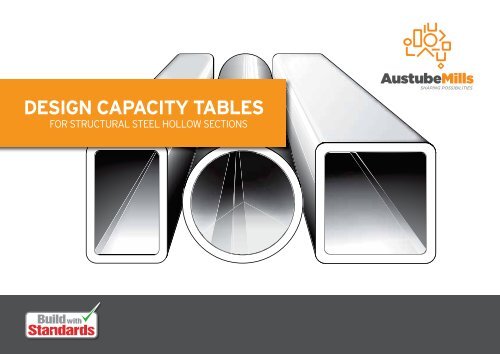
DESIGN CAPACITY TABLESFOR STRUCTURAL STEEL HOLLOW SECTIONS
Design Capacity Tables for Structural Steel Hollow SectionsAustralian Tube <strong>Mills</strong>A.B.N. 21 123 666 679DESIGN CAPACITY TABLES FOR STRUCTURAL STEEL HOLLOW SECTIONSPublished by:AUSTRALIAN TUBE MILLSEnquiries should be addressed to the publisher:Postal address: P.O. Box 246, Sunnybank, Queensland 4109, AustraliaE-mail address: info@austubemills.comInternet: www.austubemills.com© 2013 Australian Tube <strong>Mills</strong>First issue – June 2003Second issue – December 2010Third issue – August 2013Disclaimer - Whilst every care has been taken in the preparation of this information, Australian Tube <strong>Mills</strong>, and itsagents accept no liability for the accuracy of the information supplied. The company expressly disclaims all and anyliability to any person whether a purchaser of any product, or otherwise in respect of anything done or omitted to bedone and the consequences of anything done or omitted to be done, by any such person in reliance, whether in wholeor in part upon the whole or any part of this publication.Warning - This publication should not be used without the services of a competent professional with suitableknowledge in the relevant field, and under no circumstances should this publication be relied upon to replace any orall of the knowledge and expertise of such a person.Relevance of information contained in this PublicationMaterial Standards and product qualities:USERS OF THIS PUBLICATION SHOULD NOTE THAT THE DESIGN CAPACITIES, CALCULATIONS,TABULATIONS AND OTHER INFORMATION PRESENT IN THIS PUBLICATION ARE SPECIFICALLY RELEVANTTO STRUCTURAL STEEL HOLLOW SECTIONS SUPPLIED BY Australian Tube <strong>Mills</strong>.Consequently, the information contained in this publication cannot be readily used for hollow sectionssupplied from other manufacturers as those sections may vary significantly in grade, thickness, size, materialStandard compliance (including chemical composition, mechanical properties, tolerances) and quality whencompared to structural steel hollow sections supplied from Australian Tube <strong>Mills</strong> (ATM).In many instances, the higher strengths and qualities provided by ATM structuralsteel hollow sections to obtain efficient and economical designs from structural massreductions cannot be readily provided by hollow sections from other sources.Structural steelwork/engineering Standards:The maximum design loads and design capacities listed in this publication are based on thelimit states design method of AS 4100 and the factored limit states design loads and combinationsconsidered within AS/NZS 1170. Hence, much of the information contained herein will onlybe of use to persons familiar with the limit states design method and the use of:AS 4100 Steel structuresAS/NZS 1170 Structural design actionsProduct availability & other information:As the section, grade and finish of all products are subject to continuous improvement, reference shouldbe made to the ATM PRODUCT AVAILABILITY GUIDE (PAG) for information on the availability of listedsections and associated finishes. The current version of the PAG can be found on the ATM websitewww.austubemills.com.TubeComp ® Software:Much of the information contained in this publication can also be readily obtained from the computersoftware package TubeComp® which can be run in Windows® 95, 98, 2000 and XP. TubeComp® is a simplecalculator for structural steel hollow sections designed to AS 4100:1998. TubeComp® can provide exactcalculated values for specific effective lengths and screens are dynamically updated when data is entered.Most of the information in this publication can be obtained by just four “clicks of a mouse” in TubeComp®which can be freely obtained by contacting ATM or visiting www.austubemills.com.Australian Tube <strong>Mills</strong> A.B.N. 21 123 666 679. PO Box 246 Sunnybank, Queensland 4109 Australia Telephone +61 7 3909 6600 Facsimile +61 7 3909 6660 E-mail info@austubemills.com Internet www.austubemills.comDesign Capacity Tables for Structural Steel Hollow SectionsAUGUST 2013(ii)
ForewordAustralian Tube <strong>Mills</strong> is one of the world’s premier producers of welded steel tube and pipe forstructural, mechanical and low pressure reticulation applications. For many years, Australian Tube<strong>Mills</strong> has been at the industry forefront with numerous innovations delivering significant valueto a wide range of key industries. With manufacturing facilities strategically located in Australia(Brisbane, Newcastle, Melbourne and Perth), Australian Tube <strong>Mills</strong> is effectively placed to supplyhigh quality tubular steel products to markets in Australia, New Zealand, South Pacific and South-East Asia.Australian Tube <strong>Mills</strong>’ innovative approach to the development of tubular products has beennoted by various industries for many years. This has included the introduction and ongoingpush of higher strength RHS and Pipe products which reduce weight and cut costs for endusers.Strength enhancements began with Grade C350L0 (“TruBlu”), then Grade C450L0(“GreensTuf”) and DuraGal ® and now C450PLUS ® (previously DualGrade ® C350L0/C450L0)products. Australian Tube <strong>Mills</strong> were the first to develop and promote these grades into AustralianStandards and its market areas and now offer the largest range of C450PLUS ® sections – notonly in Australia but across the world.Development of tubular shapes has also been an important strategy for Australian Tube <strong>Mills</strong>.Specific shapes (some of which carry patents and trademarks) were developed for definedindustries and include the SiloTube, UniRail, StockRail and Architectural sections. Limited rollingsof other forms of hollow sections can be supplied on a special order basis.Apart from material improvements, Australian Tube <strong>Mills</strong>’ plants also produce different typesof coating systems for tubular products. Revolutionary primer-paint systems were developedwith industry participation to protect hollow sections from rust during warehouse storage,transportation and fabrication as well as offer a smooth clean work surface during and afterfabrication.Australian Tube <strong>Mills</strong> now supplies the largest range of welded tubular steel products in Australiawhich vary in shape, grade and finish.Compared to other steel products, the worldwide consumption of welded tubular steel productsis significantly increasing. The main reasons for this outcome is due to the aesthetics, engineeringefficiencies, cost-effectiveness, increased specifier/end-user awareness and the high valueaddinginherent with tubular products. This has now firmly positioned Australian Tube <strong>Mills</strong> as thepreferred tubular supplier within many industries.Quality products, people and service sets Australian Tube <strong>Mills</strong> apart from its competitors.AcknowledgementsAustralian Tube <strong>Mills</strong> gratefully acknowledges the assistance provided by the Australian SteelInstitute (ASI) – previously the Australian Institute of Steel Construction (AISC) – for permitting the use oftheir “Design Capacity Tables” text and format in the development of various parts of this publication.Additionally, Australian Tube <strong>Mills</strong> wishes to acknowledge the detailed contributions from thefollowing:Russell Watkins of Australian Tube <strong>Mills</strong> for writing, generating and checking the text,tables and graphs used in this publication;OneSteel’s marketing services team for artwork and coordination; andNick van der Kreek at Australian Tube <strong>Mills</strong> for checking and updating variousaspects of this publication.Australian Tube <strong>Mills</strong> A.B.N. 21 123 666 679. PO Box 246 Sunnybank, Queensland 4109 Australia Telephone +61 7 3909 6600 Facsimile +61 7 3909 6660 E-mail info@austubemills.com Internet www.austubemills.comDesign Capacity Tables for Structural Steel Hollow Sections AUGUST 2013(iii)PART 0GeneralPART 1InformationPART 2MaterialsPART 3Section PropertiesPART 4Methods ofStructural AnalysisPART 5Members Subjectto BendingPART 6Members Subjectto Axial CompressionPART 7Members Subjectto Axial TensionPART 8Members Subjectto Combined ActionsPART 9Connections
PrefaceThe “Design Capacity Tables for Structural Steel” (DCT) suite of publications from the AustralianSteel Institute (ASI) – previously the Australian Institute of Steel Construction (AISC) – has beencommonly used by design engineers for at least a decade. The actual origin of these publicationsgoes back to 1969 when the Safe Load Tables (SLT) was published by AISC (at the time) for thethen permissible stress based steel structures Standards AS CA-1 and subsequently AS 1250.The SLT was published in six editions (the last edition being in 1987) with both hot-rolled “open”sections (e.g. UB, UC, PFC, etc) and structural steel hollow sections (CHS, RHS and SHS)included in its contents.The release of AS 4100 Steel Structures in 1990 to supersede AS 1250 saw a change in designphilosophy from permissible stress to limit states design principles. Such a change prompted therevision of the SLT to manifest itself as the DCT. The first edition of the DCT had an overall formatwhich was similar to the sixth edition of the SLT and included both open and hollow sections.However, due to the growing popularity, increasing range and innovation of hollow sectionconstruction, the DCT was effectively split in 1992 with the release of the “Design CapacityTables for Structural Steel Hollow Sections” (DCTHS) which only considered tubular members.Thereafter, a second edition of the DCTHS was released in 1999 entitled “Design Capacity Tablesfor Structural Steel – Volume 2: Hollow Sections” (DCT-v2:HS).While somewhat of a challenge, the aim of the DCT-v2:HS (and preceding DCTHS/DCT) was toprovide current information on hollow sections available from various manufacturers. However,at the time of publication, the consolidated product range listing from each of the manufacturerswas disjointed and not reflective of available sections. Even though the DCT-v2:HS listed a largerange of hollow sections, this positive aspect was negated by imprecise information on productavailability. Various manufacturers also complicated the situation by producing their own versionsof the DCTHS even though they had a smaller product/size range. Subsequent market studiesby Australian Tube <strong>Mills</strong> revealed that there was growing specifier and industry frustration fromthe numerous but fragmented publications available that attempted to describe the total range ofhollow sections compliant with Australian Standards. Market feedback also indicated some levelof confusion with what sizes were available in various grades. There was no ready answer to thisfrustration and confusion – unless, of course, a single manufacturer could confidently supply atotal consistent range of hollow sections.As part of its ongoing Sales & Marketing strategies, and after much analysis, Australian Tube<strong>Mills</strong> are undertaking various initiatives to significantly grow the tubular market with a substantialincrease in product range and technical support. Prior to this initiative, one of the limitations withtubular construction was the restricted range of large readily available hollow sections that arefully compliant with Australian Standards. For RHS/SHS this was seen to typically “top out” at250 x 250 SHS with thickness up to 9 mm thick. The situation with CHS was slightly different withthe availability of larger “down-graded” line-pipe though there were some issues reported on thecompliance of such products to the structural requirements of AS/NZS 1163 Grade C350L0.The ability to supply a full range of structural steel hollow sections coupled with the ability toease industry frustration from the lack of consolidated correct information of such sections alsosees Australian Tube <strong>Mills</strong> providing a large array of technical/marketing media (i.e. literature andsoftware). Part of the media includes this DCTHS which is based on AS 4100–1998.In order to embrace the acceptance level of the previously published industry document, thisAustralian Tube <strong>Mills</strong> A.B.N. 21 123 666 679. PO Box 246 Sunnybank, Queensland 4109 Australia Telephone +61 7 3909 6600 Facsimile +61 7 3909 6660 E-mail info@austubemills.com Internet www.austubemills.comDesign Capacity Tables for Structural Steel Hollow SectionsAUGUST 2013(iv)
Preface (continued)DCTHS follows the same format as the ASI/AISC DCTHS. This means that the Parts of thispublication follow the same numeric sequence as those in the ASI/AISC DCTHS and AS 4100.The tabulated data and much of the text in this publication also follows the same format andsequence as the ASI/AISC DCTHS which now makes it a ready companion to the DCT for hotrolled“open” sections. Hence, if readers are familiar with the current ASI/AISC DCTs they will alsobe familiar with this publication.Whilst based on the ASI/AISC DCTHS, some minor revisions, corrections and updates wereincorporated in this publication as well as recognition of the changed “loading” Standards to AS/NZS 1170 and other related Standards. Also, readers will note that this publication is producedin “landscape” format – i.e. the width of the page is the longer dimension. The rationale behindthis modification followed industry surveys that noted the generally published “portrait” format didnot suit publications substantially containing landscape tables. Consequently, this and severalother Australian Tube <strong>Mills</strong> publications have been produced in landscape format. For additionalinformation, readers should also refer to page (ii) for the appropriate use of this DCTHS.As a complementary design aid to this publication, Australian Tube <strong>Mills</strong> has also produced asimple calculator for structural steel hollow sections designed to AS 4100. Called TubeComp ® ,the software provides much of the information contained in this publication with just four (4)“clicks of a mouse”. The data screens of TubeComp ® are dynamically updated and can provideexact values of design capacities for effective lengths not listed in the tables of this publicationwithout the need for linear interpolation or extrapolation. TubeComp ® , like this and otherpublications, are freely available from Australian Tube <strong>Mills</strong> by using the contact details notedbelow.It is interesting to note that after nearly twenty years since the release of the first DCTHS, thesame basic team involved in the first document has been brought together to develop thispublication. This team includes engineers for computations, content and project management aswell as graphic designers. Accordingly, we trust this publication is of value to designers of hollowsection construction and would appreciate any feedback on its adequacy or ways to refine it.May your designs in tubular construction be fruitful ones!Arun SyamEditor & Tubular Development ManagerAustralian Tube <strong>Mills</strong>Australian Tube <strong>Mills</strong> A.B.N. 21 123 666 679. PO Box 246 Sunnybank, Queensland 4109 Australia Telephone +61 7 3909 6600 Facsimile +61 7 3909 6660 E-mail info@austubemills.com Internet www.austubemills.comDesign Capacity Tables for Structural Steel Hollow Sections AUGUST 2013(v)PART 0GeneralPART 1InformationPART 2MaterialsPART 3Section PropertiesPART 4Methods ofStructural AnalysisPART 5Members Subjectto BendingPART 6Members Subjectto Axial CompressionPART 7Members Subjectto Axial TensionPART 8Members Subjectto Combined ActionsPART 9Connections
Notation & AbbreviationsA eA gA nAISCASIbb b , b bf , b bwb fb sCC250L0C350L0C450L0effective sectional area of a hollow section in shear, or effective area of acompression membergross area of a cross-sectionnet area of a cross-sectionAustralian Institute of Steel Construction (now ASI)Australian Steel Institute (formerly AISC)width of a sectionbearing widthswidth of a flangestiff bearing lengthtorsional modulus for a cross-section; or Compact section (in bending)cold-formed Grade C250 hollow section to AS/NZS 1163 with L0 propertiescold-formed Grade C350 hollow section to AS/NZS 1163 with L0 propertiescold-formed Grade C450 hollow section to AS/NZS 1163 with L0 propertiesC450PLUS RHS/SHS which satisfy the strength and elongation requirementsof AS/NZS 1163 Grade C350L0 and C450L0CHSc mdd od 1d 5Circular Hollow Section(s)factor for unequal momentsdepth of a sectionoutside diameter of a Circular Hollow Section (CHS)clear depth between flangesflat width of webDN nominal size OD for Pipe (CHS) sections (as noted in AS 1074)EERWFLRYoung’s modulus of elasticity, 200 x 10 3 MPaelectric resistance weldingmaximum value of (beam) segment length for Full Lateral Restraintf u tensile strength used in design, as defined in AS 4100f y yield stress used in design, as defined in AS 4100f* va average design shear stress in a webf* vm maximum design shear stress in a webGshear modulus of elasticity, 80 x 10 3 MPa; or nominal permanent actions (e.g. deadloads)G* design (factored) permanent actions (e.g. dead loads)h sII wI xI yJk ek fk lk rk smk tk vLL estorey heightsecond moment of area of a cross-sectionwarping constant for a cross-section (≈0 for hollow sections)I about the cross-section major principal x-axisI about the cross-section minor principal y-axistorsion constant for a cross-sectionmember effective length factorform factor for members subject to axial compressioneffective length factor for load heighteffective length factor for restraint against lateral rotationexposed surface area to mass ratiocorrection factor for distribution of forces in a tension member;or effective length factor for twist restraintsratio of flat width of web (d 5 ) to thickness (t) of hollow sectionspan or member length; or sub-segment length (also see note at end of notation)effective length of a compression member or laterally unrestrained member(also see note at end of notation)L0 impact properties (as noted in AS/NZS 1163)M bnominal member moment capacityAustralian Tube <strong>Mills</strong> A.B.N. 21 123 666 679. PO Box 246 Sunnybank, Queensland 4109 Australia Telephone +61 7 3909 6600 Facsimile +61 7 3909 6660 E-mail info@austubemills.com Internet www.austubemills.comDesign Capacity Tables for Structural Steel Hollow SectionsAUGUST 2013(vi)
Notation & Abbreviations (continued)M bxM cxM iM ixM iyM oM oaM oxM rxM ryM sM sxM syM b about major principal x-axislesser of M ix and M oxnominal in-plane member moment capacityM i about major principal x-axisM i about minor principal y-axisreference elastic buckling moment for a member subject to bending;or nominal out-of-plane member moment capacityamended elastic buckling moment for a member subject to bendingM o about major principal x-axisM s about major principal x-axis reduced by axial forceM s about minor principal y-axis reduced by axial forcenominal section moment capacityM s about major principal x-axisM s about minor principal y-axisM* design bending momentM* m maximum calculated design bending moment along the length of a member orsegmentM* x design bending moment about major principal x-axisM* y design bending moment about minor principal y-axisNNon-compact section (in bending)nominal member capacity in axial compressionN cN cxN cyN omN ombN sN c for member buckling about major principal x-axisN c for member buckling about minor principal y-axiselastic buckling loadN om for a braced membernominal section capacity of a concentrically loaded compression memberN tnominal section capacity in tensionN* design axial force, tensile or compressivenaxis through corners of a SHSn/a not applicableOD outside diameter (for CHS)ATM Australian Tube <strong>Mills</strong>Papplied concentrated loadPAG Product Availability Guide by Australian Tube <strong>Mills</strong>Qnominal imposed actions (e.g. live loads)Q* design (factored) imposed actions (e.g. live loads)R bR bbR byR urr extr xr ynominal bearing capacity of a webnominal bearing buckling capacity of a webnominal bearing yield capacity of a webnominal capacityradius of gyration; or radiusoutside radius of hollow sectionradius of gyration about major principal x-axisradius of gyration about minor principal y-axisR* design bearing force; or design reactionøR u design capacityRHS Rectangular Hollow Section(s)Splastic section modulus; or Slender section (in bending)S xS y(plastic) S about major principal x-axis(plastic) S about minor principal y-axisS* design action effect, as defined in AS 4100SHS Square Hollow Section(s)Australian Tube <strong>Mills</strong> A.B.N. 21 123 666 679. PO Box 246 Sunnybank, Queensland 4109 Australia Telephone +61 7 3909 6600 Facsimile +61 7 3909 6660 E-mail info@austubemills.com Internet www.austubemills.comDesign Capacity Tables for Structural Steel Hollow Sections AUGUST 2013(vii)PART 0GeneralPART 1InformationPART 2MaterialsPART 3Section PropertiesPART 4Methods ofStructural AnalysisPART 5Members Subjectto BendingPART 6Members Subjectto Axial CompressionPART 7Members Subjectto Axial TensionPART 8Members Subjectto Combined ActionsPART 9Connections
Notation & Abbreviations (continued)tthickness of a sectiont ft wUNOV uV vV vmthickness of a flangethickness of a webunless noted otherwisenominal shear capacity of a web with a uniform shear stress distributionnominal shear capacity of a webnominal shear capacity of a web in the presence of bending momentV* design shear forceWtotal uniformly distributed applied loadW* design action; or design (factored) WW EM * equivalent strength Maximum Design Load based on Moment (Table T5.1)W ES * equivalent serviceability Maximum Design Load based on Deflection (Table T5.1)W EV * equivalent strength Maximum Design Load based on Shear (Table T5.1)W* L strength limit state maximum design loadW L1 * W* L based on design moment capacityW L2 * W* L based on design shear capacityW* S serviceability limit state maximum design loadW* S1 W* S based on deflection limitW* YL W* S based on first yield loadxmajor principal axis coordinateyminor principal axis coordinateZelastic section modulusZ eZ exZ eyZ nZ xZ yeffective section modulusZ e for bending about major principal x-axisZ e for bending about minor principal y-axisZ about the n-axis through the corners of an SHSZ for bending about major principal x-axisZ for bending about minor principal y-axis a b c m s T m s b b m scompression member factorcompression member section constantcompression member slenderness reduction factormoment modification factor for bendingslenderness reduction factorcoefficient of thermal expansionratio of smaller to larger bending moments at the ends of a memberratio for compression member stiffness to end restraint stiffnessdeflectiontranslational displacement of the top relative to the bottom for a storey heightmoment amplification factor for a braced membermoment amplification factor, taken as the greater of b and smoment amplification factor for a sway membercompression member factorcompression member imperfection factor pi ( 3.14159)slenderness ratio c e ep ey nNotes:elastic buckling load factorplate element slendernessplate element plasticity slenderness limitplate element yield slenderness limitmodified compression member slendernessPoisson’s ratiodensity of a materialcapacity factor1. The Tables use L e and L in lieu of l e and l respectively (as noted in AS 4100) to avoid confusion with the standard typeface used.Australian Tube <strong>Mills</strong> A.B.N. 21 123 666 679. PO Box 246 Sunnybank, Queensland 4109 Australia Telephone +61 7 3909 6600 Facsimile +61 7 3909 6660 E-mail info@austubemills.com Internet www.austubemills.comDesign Capacity Tables for Structural Steel Hollow SectionsAUGUST 2013(viii)
Standard and Other ReferencesThe Australian Standards referred to in this publication are centrally listed in Section 1.1.2. Otherreferences are listed at the end of the initial text portion in each respective Part of the publication(i.e. prior to the main table listings).Australian Tube <strong>Mills</strong> A.B.N. 21 123 666 679. PO Box 246 Sunnybank, Queensland 4109 Australia Telephone +61 7 3909 6600 Facsimile +61 7 3909 6660 E-mail info@austubemills.com Internet www.austubemills.comDesign Capacity Tables for Structural Steel Hollow Sections AUGUST 2013(ix)PART 0GeneralPART 1InformationPART 2MaterialsPART 3Section PropertiesPART 4Methods ofStructural AnalysisPART 5Members Subjectto BendingPART 6Members Subjectto Axial CompressionPART 7Members Subjectto Axial TensionPART 8Members Subjectto Combined ActionsPART 9Connections
Blank PageAustralian Tube <strong>Mills</strong> A.B.N. 21 123 666 679. PO Box 246 Sunnybank, Queensland 4109 Australia Telephone +61 7 3909 6600 Facsimile +61 7 3909 6660 E-mail info@austubemills.com Internet www.austubemills.comDesign Capacity Tables for Structural Steel Hollow Sections AUGUST 2013(x)
Part 1INTRODUCTIONSection1.1 General 1-21.1.1 Steel Structures Standards 1-21.1.2 Reference Standards 1-21.1.3 Table Format and Usage 1-21.2 Range of Structural Steel Grades and Sections 1-21.3 Units 1-21.4 Limit States Design using these Tables 1-31.5 Table Contents 1-41.6 References 1-4PageThe maximum design loads and design capacities listed in thispublication are based on the limit states design method of AS 4100 andthe factored limit states design actions and combinations con sidered withinAS/NZS 1170. Hence, much of the information contained herein will only be ofuse to persons familiar with the limit states design method and the use of:AS 4100 Steel structuresAS/NZS 1170 Structural design actionsSee Section 2.1 for the specific Material Standard (AS/NZS 1163)referred to by the section type and steel grade in these Tables.Australian Tube <strong>Mills</strong> A.B.N. 21 123 666 679. PO Box 246 Sunnybank, Queensland 4109 Australia Telephone +61 7 3909 6600 Facsimile +61 7 3909 6660 E-mail info@austubemills.com Internet www.austubemills.comDesign Capacity Tables for Structural Steel Hollow Sections AUGUST 20131-1PART 0GeneralPART 1InformationPART 2MaterialsPART 3Section PropertiesPART 4Methods ofStructural AnalysisPART 5Members Subjectto BendingPART 6Members Subjectto Axial CompressionPART 7Members Subjectto Axial TensionPART 8Members Subjectto Combined ActionsPART 9Connections
Part 1INTRODUCTION1.1 General1.1.1 Steel Structures StandardThe tables in this publication have been calculated in accordance with the Australian StandardAS 4100–1998 Steel Structures. As far as possible, the notation and terminology used are thesame as those adopted in that Standard.Cold-formed hollow sections manufactured in accordance with Australian Standard AS/NZS1163:2009 Structural Steel Hollow Sections are included within the scope of AS 4100. Extensiveresearch [1.1,1.2,1.3] undertaken over a number of years has confirmed that cold-formed hollowsections compliant with AS/NZS 1163 meet the inherent requirements of AS 4100. Cold-formedhollow sections may also be designed to AS/NZS 4600:2005 Cold-Formed Steel Structures whichis outside of the scope of this publication.1.1.2 Reference Standards“AS 1074” refers to AS 1074–1989 Steel tubes and tubulars for ordinary service“AS 4100” refers to AS 4100–1998 Steel structures“AS/NZS 1163” refers to AS/NZS 1163:2009 Cold-formed structural steel hollow sections“AS/NZS 1170” refers to AS/NZS 1170:2002 Structural design actions“AS/NZS 1554.1” refers to AS/NZS 1554.1:2011 Structural steel welding – Welding of steel structures“AS/NZS 2312” refers to AS/NZS 2312:2002 Guide to the protection of structural steel againstatmospheric corrosion by the use of protective coatings“AS/NZS 4600” refers to AS/NZS 4600:2005 Cold-formed steel structures“AS/NZS 4792” refers to AS/NZS 4792:2006 Hot-dip galvanized (zinc) coatings on ferrous hollowsections, applied by a continuous or a specialized process1.1.3 Table Format and UsageWithin this publication the terms “Table” and “Tables” refer to information in this edition and volumeof the Design Capacity Tables for Structural Steel Hollow Sections by Australian Tube <strong>Mills</strong>.A brief list of the Tables’ contents is provided in Section 1.5. It should be noted that the maintables listing design capacities and other member information are placed at the end of theinitial text portion of each Part of this publication. The main tables will generally be listed within anumerical sequence – e.g. Table 5.1 series (Maximum Design Loads for Simply Supported Beamswith Full Lateral Restraint), Table 5.2 series (Design Section Moment and Web Capacities),Table 5.3 series (Design Moment Capacities for Members without Full Lateral Restraint), etc.Any table listed in the (initial) text portion of each Part of this Publication will have a “T” before theTable number – e.g. Table T2.1 in Section 2.2.1.2 Range of Structural Steel Grades and SectionsThe Tables contain information on the currently available (at the time of publication) structuralsteel hollow sections supplied by Australian Tube <strong>Mills</strong> (ATM) which fully comply with AS/NZS1163. Section 2 should be consulted for further details on the structural steel hollow sectionsconsidered in the Tables.Reference should also be made to the Australian Tube <strong>Mills</strong> Product Availability Guide (PAG) forgeneral information on the availability of the listed sections and associated finishes.1.3 UnitsThe units in the Tables are consistent with those in the SI (metric) system. The base unitsutilised in the Tables are newton (N) for force, metre (m) for length, and kilogram (kg) for mass.Where noted, stress is expressed in megapascals (MPa).With some minor exceptions, all values in the Tables are rounded to three (3) significant figures.Australian Tube <strong>Mills</strong> A.B.N. 21 123 666 679. PO Box 246 Sunnybank, Queensland 4109 Australia Telephone +61 7 3909 6600 Facsimile +61 7 3909 6660 E-mail info@austubemills.com Internet www.austubemills.comDesign Capacity Tables for Structural Steel Hollow Sections AUGUST 2013 1-2
Part 1INTRODUCTION1.4 Limit States Design using these TablesAS 4100 sets out the minimum requirements for the design, fabrication and erection of steelworkin accordance with the limit states design method and follows a semi-probabilistic limit stateapproach presented in a deterministic format.Definition of limit states – When a structure or part of a structure is rendered unfit for use it reachesa ‘limit state’. In this state it ceases to perform the functions or to satisfy the conditions for whichit was designed. Relevant limit states for structural steel include strength, serviceability, stability,fatigue, brittle fracture, fire, and earthquake. Only two limit states are considered in the Tables –the strength limit state and, where applicable, the serviceability limit state.Limit states design requires structural members and connections to be proportioned such thatthe design action effect (S*) resulting from the design action (W*), is less than or equal to thedesign capacity (R u ) i.e.S* R uDesign action or design load (W*) is the combination of the nominal actions or loadsimposed upon the structure (e.g. transverse loads on a beam) multiplied by the appropriateload combination factors as specified in AS/NZS 1170 (Structural design actions). These designactions/loads are identified by an asterisk ( * ) after the appropriate action/load (e.g. W* L is themaximum design transverse load on a beam).Design action effects (S*) are the actions (e.g. design bending moments, shear forces, axialloads) calculated from the design actions or design loads using an acceptable methodof analysis (Section 4 of AS 4100). These effects are identified by an asterisk ( * ) after theappropriate action effect (e.g. M* describes the design bending moment).Design capacity (R u ) is the product of the nominal capacity (R u ) and the appropriate capacityfactor () found in Table 3.4 of AS 4100. R u is determined from the characteristic values andspecified parameters found in Sections 5 to 9 of AS 4100.For example, consider the strength limit state design of a simply supported beam which has fulllateral restraint subject to a total transverse design load (W*) distributed uniformly along the beam.For flexure, the appropriate design action effect (S*) is the design bending moment (M*)which is determined by:M* =W*L8where L = span of the beam.In this case the design capacity (R u ) is equal to the design section moment capacity (M s ),given by: M s = f y Z ewhere = the capacity factorf y = yield stress used in designZ e = effective section modulusTo satisfy the strength limit state, the following relationship (equivalent to S* R u ) is used:M* M sThe maximum design bending moment (M*) is therefore equal to the design sectionmoment capacity (M s ), and the maximum design load is that design load (W*) whichcorresponds to the maximum M*. (It should be noted that other checks on the beam may benecessary – e.g. shear capacity, bearing capacity, etc).When considering external loads, in the context of this publication, the maximum design load(W* L ) given in the relevant table must be greater than or equal to the imposed design load (W*).Where applicable, the Tables give values of design capacity (R u ) and maximum designload (W* L ) determined in accordance with AS 4100. When using the Tables, the designer mustdetermine the relevant strength limit state design action (W*) and/or corresponding designaction effect (S*) to ensure that the strength limit state requirements of AS 4100 are satisfied.Where relevant, other limit states (e.g. serviceability, fatigue, etc) must also be considered bythe designer. Some useful information for checking the serviceability limit state is included in theTables.Australian Tube <strong>Mills</strong> A.B.N. 21 123 666 679. PO Box 246 Sunnybank, Queensland 4109 Australia Telephone +61 7 3909 6600 Facsimile +61 7 3909 6660 E-mail info@austubemills.com Internet www.austubemills.comDesign Capacity Tables for Structural Steel Hollow Sections AUGUST 20131-3PART 0GeneralPART 1InformationPART 2MaterialsPART 3Section PropertiesPART 4Methods ofStructural AnalysisPART 5Members Subjectto BendingPART 6Members Subjectto Axial CompressionPART 7Members Subjectto Axial TensionPART 8Members Subjectto Combined ActionsPART 9Connections
Part 1INTRODUCTION1.5 Table ContentsFor the range of structural steel grades and sections considered, tables are provided for:(i)(ii)(iii)section dimensions and section properties:– Dimensions and Properties + Properties for Design to AS 4100 (PART 3)– Fire Engineering Design (PART 3)– Telescoping Information (PART 3)design capacity (R u ) for:– Members Subject to Bending (PART 5)– Members Subject to Axial Compression (PART 6)– Members Subject to Axial Tension (PART 7)– Members Subject to Combined Actions (PART 8)maximum design load (W*) for:– Strength Limit State (W* L ) for Beams (PART 5)– Serviceability Limit State (W* S ) for Beams (PART 5)Acceptable methods of analysis for determining the design action effects are defined in Section 4of AS 4100 and material relevant to some of these methods of analysis is briefly presented in Part4 of this publication.1.6 References[1.1] Hasan, S.W. and Hancock, G.J., “Plastic Bending Tests of Cold-FormedRectangular Hollow Sections”, Steel Construction, Vol. 23, No. 4, Australian Instituteof Steel Construction, 1989 (Note: AISC is now ASI – Australian Steel Institute).[1.2] Key, P.W., Hasan, S.W. and Hancock, G.J., “Column Behaviour of Cold-FormedHollow Sections”, Journal of Structural Engineering, American Society of Civil Engineers,Vol. 114, No. 2, 1988.[1.3] Zhao, X.L. and Hancock, G.J., “Tests to Determine Plate Slenderness Limits forCold-Formed Rectangular Hollow Sections of Grade C450”, Steel Construction, Vol. 25,No. 4, Australian Institute of Steel Construction, 1991 (Note: AISC is now ASI –Australian Steel Institute).See Section 1.1.2 for details on reference Standards.Australian Tube <strong>Mills</strong> A.B.N. 21 123 666 679. PO Box 246 Sunnybank, Queensland 4109 Australia Telephone +61 7 3909 6600 Facsimile +61 7 3909 6660 E-mail info@austubemills.com Internet www.austubemills.comDesign Capacity Tables for Structural Steel Hollow Sections AUGUST 2013 1-4
Part 2MATERIALSSection2.1 Range of Structural Steel Grades and Sections 2-22.1.1 Specifications 2-22.2 Yield Stress and Tensile Strength 2-32.3 Properties of Steel 2-32.3.1 Masses 2-32.4 Grades 2-32.4.1 Circular Hollow Sections (CHS) 2-32.4.2 Rectangular/Square Hollow Sections (RHS/SHS) and C450PLUS ® 2-42.5 Mill Surface Finishes 2-52.6 Hollow Sections Not Compliant with AS/NZS 1163 2-52.7 Availability 2-62.8 References 2-6PageSee Section 2.1 for the specific Material Standard (AS/NZS 1163)referred to by the section type and steel grade in these Tables.Australian Tube <strong>Mills</strong> A.B.N. 21 123 666 679. PO Box 246 Sunnybank, Queensland 4109 Australia Telephone +61 7 3909 6600 Facsimile +61 7 3909 6660 E-mail info@austubemills.com Internet www.austubemills.comDesign Capacity Tables for Structural Steel Hollow Sections AUGUST 20132-1PART 0GeneralPART 1InformationPART 2MaterialsPART 3Section PropertiesPART 4Methods ofStructural AnalysisPART 5Members Subjectto BendingPART 6Members Subjectto Axial CompressionPART 7Members Subjectto Axial TensionPART 8Members Subjectto Combined ActionsPART 9Connections
Part 2MATERIALS2.1 Range of Structural Steel Grades and SectionsThese Tables cover the full range of structural steel hollow sections supplied by Australian Tube<strong>Mills</strong> manufactured in accordance with AS/NZS 1163.The section sizes and their respective grades listed in the Tables include:AS/NZS 1163 Grade C250L0 Circular Hollow Sections (CHS)AS/NZS 1163 Grade C350L0 Circular Hollow Sections (CHS)AS/NZS 1163 Grade C350L0 Rectangular Hollow Sections (RHS) (‘small’ sizes only)AS/NZS 1163 Grade C450PLUS ® RHSAS/NZS 1163 Grade C350L0 Square Hollow Sections (SHS) (‘small’ sizes only)AS/NZS 1163 Grade C450PLUS ® SHSThe grade designation (e.g. C450L0) is based on the nominal minimum yield strength of thesteel (in MPa). The prefix ‘C’ is used before the value of the nominal yield strength of the steelto indicate that the section is cold-formed. It should be noted that AS/NZS 1163 only considerscold-formed structural steel hollow sections. The suffix ‘L0’ denotes impact properties at 0°C asspecified in AS/NZS 1163. Hollow sections rated with impact properties such as L0 are not onlyimportant in lower temperature environments but also for welded structures subject to dynamicloads. This becomes much more important for hollow sections with larger thickness (i.e. t 6.0 mm).AS/NZS 1163 Grade C450PLUS ® RHS/SHS comply with the strength and elongationrequirements of both Grade C350L0 and C450L0. The key mechanical properties of C450PLUS ®are covered in Section 2.2 and a further description of C450PLUS ® is given in Section 2.4.Where relevant, C450PLUS ® RHS/SHS are designed as AS/NZS 1163 Grade C450L0 sections inthese Tables to capitalise on the higher strength benefits of this steel grade – see Section 2.4.2.C450PLUS ® are registered trademarks of Australian Tube <strong>Mills</strong>.Further general information on the availability of the sections listed in the Tables is noted inSection 2.7.2.1.1 SpecificationsHollow sections supplied by Australian Tube <strong>Mills</strong> are manufactured by cold-forming and highfrequencyElectric Resistance Welding (ERW). The ERW process allows cold-formed hollowsections to be welded at ambient temperatures without subsequent stress relieving.However, the Tables only apply to those hollow sections manufactured in accordance withAS/NZS 1163 and supplied by Australian Tube <strong>Mills</strong>.Specifiers should also note that hollow sections not complying with AS/NZS 1163 may berequired to be down-graded in yield stress, tensile strength and other mechanical propertieswhen designing to AS 4100 and welding to AS/NZS 1554.1 – see Section 2.6.To ensure the assumptions, product benefits and quality of structural steel hollow sectionsconsidered in these Tables, designers should specifically nominate AS/NZS 1163 compliantproduct in their specifications and general notes. Such wording may be:Unless Noted Otherwise –CHS to comply with AS/NZS 1163–C350L0RHS/SHS to comply with AS/NZS 1163–C450L0Note, for SHS with overall dimensions of 50 x 50 and smaller (and equivalent perimeter RHS),ATM typically supplies these sizes in Grade C350L0 to AS/NZS 1163. However, these sizes areavailable ex-rolling to AS/NZS 1163-C450L0 subject to minimum order requirements.By specifying AS/NZS 1163–C450L0 RHS/SHS in the general notes and specifications it will alsosignal the fabricator to use typically available, prequalified higher strength welding consumables(i.e. E49/W50). This is generally reinforced by the welding part of the specification and generalnotes which flags the welding consumables to be E49/W50 – unless noted otherwise – as this istypical practice. However, should designers not utilise the higher strength benefits of C450PLUS ®and only use its C350L0 properties, this can be indicated outside of the general notes andspecification at the appropriate drawing arrangement or detail.Australian Tube <strong>Mills</strong> A.B.N. 21 123 666 679. PO Box 246 Sunnybank, Queensland 4109 Australia Telephone +61 7 3909 6600 Facsimile +61 7 3909 6660 E-mail info@austubemills.com Internet www.austubemills.comDesign Capacity Tables for Structural Steel Hollow Sections AUGUST 2013 2-2
Part 2MATERIALSIt should be noted that Australian Tube <strong>Mills</strong> also supplies AS/NZS 1163–C250L0 CHS and, ifused and specified, they can also be flagged as such in the relevant part of the engineering/workshop drawings, material lists and/or bills of quantities with the default Standard and gradespecification as noted above.The importance of “L0” impact properties cannot be understated (as noted in Section 2.1) andhas to be included in the grade designations of general notes, specifications and other points ofsteel grade reference.In conjunction with the above structural steel hollow section Standard and grade designations,further information on the appropriate specification of structural steelwork can be found inRef.[2.1] or by contacting Australian Tube <strong>Mills</strong>.2.2 Yield Stress and Tensile StrengthTable T2.1 lists the minimum yield stresses and tensile strengths for the structural steel hollowsection grades covered by this publication and used for calculating the design capacities.TABLE T2.1: Yield Stress and Tensile Strength based on Steel GradeAustralian Standard Section Type Steel GradeAS/NZS 1163Yield Stressf yMPaTensile Strengthf uMPaCHS C250L0 250 320CHS C350L0 350 430RHS/SHSC450PLUS ®(designed as C450L0)450 500NOTE: See Section 2.4 for a definition of C450PLUS ® and its use in these Tables.More detailed information on the strengths and other mechanical properties of these steels canbe found in Table 2.1 of AS 4100, AS/NZS 1163, other ATM product guides or by contacting ATM(by the contact details noted at the bottom of the page).2.3 Properties of SteelThe properties of steel adopted in this publication are shown in Table T2.2. Properties such asPoisson’s Ratio and Coefficient of Thermal Expansion for structural steel are also listed in Table T2.2.TABLE T2.2: Properties of SteelProperty Symbol ValueYoung's Modulus of Elasticity E 200 x 10 3 MPaShear Modulus of Elasticity G 80 x 10 3 MPaDensity 7850 kg/m 3Poisson's Ratio 0.25Coefficient of Thermal Expansion T11.7 x 10 -6 per ºC2.3.1 MassesThe masses given in these Tables are based on a steel density of 7850 kg/m 3 , the nominal sectionsize and standard corner radii (see Section 3.2.1.2). In practice the tabulated values are affectedby rolling tolerances and actual corner shape. Masses per metre listed are for the sections only,and do not include any allowances for cleats, end plates, weld metal, etc.2.4 Grades2.4.1 Circular Hollow Sections (CHS)Australian Tube <strong>Mills</strong> (ATM) offers CHS in two AS/NZS 1163 grades: C250L0 and C350L0.The Grade C350L0 products provide a more comprehensive range of sections for structuralapplications and should be commonly specified. ATM also provide CHS/Pipe productswhich comply with AS 1074 and AS/NZS 1163–C250L0 for structural and low pressure pipingapplications. As the sizes supplied in the C250L0 CHS range are used in structural applications,they are also offered as Structural CHS by ATM.Australian Tube <strong>Mills</strong> A.B.N. 21 123 666 679. PO Box 246 Sunnybank, Queensland 4109 Australia Telephone +61 7 3909 6600 Facsimile +61 7 3909 6660 E-mail info@austubemills.com Internet www.austubemills.comDesign Capacity Tables for Structural Steel Hollow Sections AUGUST 20132-3PART 0GeneralPART 1InformationPART 2MaterialsPART 3Section PropertiesPART 4Methods ofStructural AnalysisPART 5Members Subjectto BendingPART 6Members Subjectto Axial CompressionPART 7Members Subjectto Axial TensionPART 8Members Subjectto Combined ActionsPART 9Connections
Part 2MATERIALS2.4.2 Rectangular/Square Hollow Sections (RHS/SHS) and C450PLUS ®Due to the nature of manufacturing cold-formed hollow sections, RHS/SHS generally have higherstrengths and lower elongations (from tensile tests) than CHS manufactured from the sametype of feed-coil. This is basically due to the additional cold-working RHS/SHS receive duringthe sizing and finishing stages of shape formation. Consequently, from the three basic strengthgrades noted in AS/NZS 1163, CHS are generally supplied in grades C250L0 and C350L0whereas RHS/SHS are supplied in the higher strengths of grades C350L0 and C450L0.Australian Tube <strong>Mills</strong> (ATM) have always been at the forefront in utilising higher strength hollowsections both in Australia and internationally. This was previously seen by ATM’s push to useGrade C350L0 for CHS, Grade C450L0 for RHS/SHS (the “GreensTuf” range) and now by offeringthe C450PLUS ® RHS/SHS across a wide range of pre-coated and uncoated products.The name C450PLUS ® is derived from satisfying two key mechanical properties from tensile tests– strength and elongation. These properties undergo opposing effects during manufacturing.As noted above, it is widely known that the cold-forming process increases material strengthsof welded cold-formed hollow sections. However, the elongation requirements of the material(a reflection of ductility) generally do not increase with strength. This is best illustrated by thefollowing extract from AS/NZS 1163: Structural Steel Hollow Sections –Table T2.3: Tensile test requirements for RHS/SHS from Table 6 of AS/NZS 1163GradeMinimum yield strength(f y )MPaMinimum tensile strength(f u )MPaMinimum elongation asa proportion of the gaugelength 5.65S oRHS, SHS b/t, d/t15 15 30 30C350L0 350 430 12% 14% 16%C450L0 450 500 10% 12% 14%C450PLUS ® 450 500 12% 14% 16%NOTE: These elongation limits apply to the face from which the tensile test is taken.The above table shows that higher strengths are developed in Grade C450L0 products andhigher elongation is attained with Grade C350L0 products. C450PLUS ® satisfies all the highervalues of these key mechanical properties (shaded in Table T2.3 and also summarised in bold inthe last row of that table).Apart from higher strength and lighter weight benefits, the reasons for Australian Tube <strong>Mills</strong>supplying C450PLUS ® RHS/SHS include:Grade C450L0 by itself may not perform well if the hollow section is bent to a tightradius during fabrication (e.g. corners in gate frames, etc). Excess straining sometimesproduces section failures. Experience has shown that Grade C450L0 products whichpossess the C350L0 elongation requirements can be adequately formed in thesesituations.Structural steelwork drawings sometimes nominate C350/C350L0 as the default (i.e.“unless noted otherwise”) grade for RHS/SHS. It is often perceived that C450L0 is anew and less readily available grade. This perception is not true as Australian Tube<strong>Mills</strong> has been supplying a large range of C450PLUS ® RHS/SHS in pre-coated anduncoated finishes for some time. However, there remains some specifiers and enduserswho wish to use C350L0 RHS/SHS. C450PLUS ® can fulfill their requirementsas well as the requirements of those who wish to specify/use higher strength C450L0and its inherent advantages.Dual-stocking of grades for a particular section is costly. If the same section cancomply with the requirements of both the commonly specified lower strength grade andthe structurally efficient higher strength grade, a lower cost product will be available tothe specifier and end-user.In order to capitalise on the benefits of C450PLUS ® ’s higher strength properties, theTables contained in this publication consider C450PLUS ® RHS/SHS to be designed withthe strength properties of AS/NZS 1163 Grade C450L0 – i.e. f y = 450 MPa and f u = 500MPa.As noted in Section 2.1, impact properties such as “L0” are not only important for low temperatureapplications but very important for welded members subject to dynamic loads. This is particularlyso for thicker hollow sections. Hence, “L0” impact rated hollow sections, which is satisfied by allof ATM AS/NZS 1163 compliant structural hollow sections, should always be specified.Further information on AS/NZS 1163 Grades C250L0, C350L0 and C450PLUS ® can be found inthe Australian Tube <strong>Mills</strong>’ (ATM) Product Manual. These and other publications and software canbe obtained freely from www.austubemills.com or by contacting ATM via the details noted at thebottom of the page.Australian Tube <strong>Mills</strong> A.B.N. 21 123 666 679. PO Box 246 Sunnybank, Queensland 4109 Australia Telephone +61 7 3909 6600 Facsimile +61 7 3909 6660 E-mail info@austubemills.com Internet www.austubemills.comDesign Capacity Tables for Structural Steel Hollow Sections AUGUST 2013 2-4
Part 2MATERIALS2.5 Mill Surface FinishesIt is commonly recognised that pre-primed and pre-coated hollow sections provide considerablebenefits and savings for fabrication construction as these sections are coated either prior, duringor immediately after the tube forming process. Australian Tube <strong>Mills</strong> are regarded as beinginnovative in various mill finishes for many years and offer tubular products in the followingsurface finishes: DuraGal ® , SupaGal ® , (semi-continuous) hot-dip galvanized, primer-painted, oiled,and NOP (no oil or paint) coatings. ATM’s galvanized coatings comply with AS/NZS 4792.It should be noted that due to manufacturing limitations, surface finishes can vary with shape andsize of hollow section. Further information on Australian Tube <strong>Mills</strong>’ (ATM) surface finishes can befound in the ATM Product Manual. These and other publications and software can be obtainedfreely from www.austubemills.com or by contacting ATM via the details noted at the bottom of thepage.AS/NZS 2312 also provides useful information on this topic.2.6 Hollow Sections Not Compliant with AS/NZS 1163A key aspect of design within the provisions of a national steel structures Standard as AS 4100 isthe inclusion of cold-formed hollow sections. This situation is highly dependent on the integrity ofthe supporting material Standards. One such material Standard is AS/NZS 1163 Structural steelhollow sections.AS/NZS 1163 has been developed to reflect the way cold-formed hollow sections have beenmanufactured, specified, fabricated and subsequently used in Australia. This includes takingaccount of the enhancement in strength due to cold-forming, superior product tolerances(including dimensional limits and the supply of minimum cross-section material as assumed indesign), ductility, weldability and resistance to impact loads.Designers and specifiers should be very wary of the substitution of AS/NZS 1163 productby either unidentified product or specific product complying with other inferior internationalStandards which do not deliver the full range of AS/NZS 1163 product requirements.AS 4100 states that hollow sections not complying with AS/NZS 1163 must be tested andchecked for compliance. Non-conforming or unidentified hollow sections must be down-rated toa design yield stress of 170 MPa and a design ultimate strength of 300 MPa.Though AS 4100 is a key Standard for the design, fabrication and erection of steelwork, otherimportant Standards are also used to produce the completed structure that is to be eventually fitfor purpose. The other important Standards for structural steel hollow sections include welding,painting and galvanizing which, in the case of structural steel hollow sections, are also dependenton compliance with AS/NZS 1163. Additionally, as noted in Sections 1.1, 1.2, 2.1 and 2.2, the useof these Tables is also based on hollow sections complying with AS/NZS 1163.Australian Tube <strong>Mills</strong> A.B.N. 21 123 666 679. PO Box 246 Sunnybank, Queensland 4109 Australia Telephone +61 7 3909 6600 Facsimile +61 7 3909 6660 E-mail info@austubemills.com Internet www.austubemills.comDesign Capacity Tables for Structural Steel Hollow Sections AUGUST 20132-5PART 0GeneralPART 1InformationPART 2MaterialsPART 3Section PropertiesPART 4Methods ofStructural AnalysisPART 5Members Subjectto BendingPART 6Members Subjectto Axial CompressionPART 7Members Subjectto Axial TensionPART 8Members Subjectto Combined ActionsPART 9Connections
Part 2MATERIALS2.7 AvailabilityThe sections listed in the Tables are normally readily available from Australian Tube <strong>Mills</strong>’distributors in standard lengths. However, the availability should be checked for larger sizes, forlarger tonnages of individual sections or for non-standard lengths.The standard lengths for Australian Tube <strong>Mills</strong> (ATM) range of structural steel hollow sections aresummarised in Table T2.4. Sections may be ordered in other lengths ex-mill rolling subject to ATMlength limitations and minimum order requirements.TABLE T2.4: Standard Length AvailabilitySection Type Sizes Standard Lengths (m)CHS – Grade C250L0 26.9 OD to 165.1 OD 6.5CHS – Grade C350L026.9 OD to 165.1 OD168.3 OD to 508 ODRHS – Grade C350L0 50 x 20 to 75 x 25 8.0RHS – Grade C450PLUS ®SHS – Grade C350L0SHS – Grade C450PLUS ®50 x 20 to 75 x 25 #75 x 50 to 250 x 150300 x 200 to 400 x 30020 x 20 to 25 x 2530 x 30 to 50 x 5020 x 20 to 25 x 25 #30 x 30 to 65 x 65 #75 x 75 to 250 x 250300 x 300 to 400 x 4006.512.08.08.0 and/or 12.0*12.06.58.06.58.08.0 and/or 12.0*12.0The list of Australian Tube <strong>Mills</strong>’ (ATM) distributors can be found in the ATM Product Manual whichis freely available from www.austubemills.com or by contacting ATM via the details noted at thebottom of the page.Standard lengths and Mass & Bundling data on Australian Tube <strong>Mills</strong>’ (ATM) structural steelhollow sections can be found in the ATM Product Manual which is freely available from www.austubemills.com or by contacting ATM via the details noted at the bottom of the page.It is highly recommended that readers always ensure that they are using current information onthe ATM product range. This can be done by reference to the ATM Product Availability Guide(PAG) as noted in www.austubemills.com.2.8 References[2.1] Syam, A.A. (ed), “A Guide to the Requirements for Engineering Drawings of StructuralSteelwork”, Steel Construction, Vol. 29, No. 3, Australian Institute of Steel Construction,September 1995 (Note: AISC is now ASI – the Australian Steel Institute).See Section 1.1.2 for details on reference Standards.Notes:* See ATM Product Manual for further details.#For small sizes up to 50 x 50 SHS and RHS of equivalent perimeter, the standard grade is AS/NZS1163 Grade C350L0.The structural steel hollow sections listed in the Tables are generally available in all AustralianTube <strong>Mills</strong>’ (ATM) market areas, however, reference should also be made to the ATM ProductAvailability Guide (PAG) for information on the availability of the listed sections, their grades andassociated finishes.Australian Tube <strong>Mills</strong> A.B.N. 21 123 666 679. PO Box 246 Sunnybank, Queensland 4109 Australia Telephone +61 7 3909 6600 Facsimile +61 7 3909 6660 E-mail info@austubemills.com Internet www.austubemills.comDesign Capacity Tables for Structural Steel Hollow Sections AUGUST 2013 2-6
Part 3SECTION PROPERTIESSection3.1 General 3-23.2 Section Property Tables 3-23.2.1 Dimensions, Ratios and Properties 3-23.2.1.1 Torsion Constants 3-23.2.1.2 Corner Radii 3-33.2.2 Properties for Design to AS 4100 3-33.2.2.1 Compactness 3-33.2.2.2 Effective Section Modulus 3-33.2.2.3 Form Factor 3-43.2.3 Example 3-43.3 Properties for Fire Design 3-53.4 Telescoping Sections 3-53.5 References 3-6PageTableTables 3.1-1 to 3.1-6Dimensions and Properties 3-7Tables 3.2-1 to 3.2-4Fire Engineering Design 3-18Tables 3.3-1 to 3.3-3Telescoping Information 3-25See Section 2.1 for the specific Material Standard (AS/NZS 1163)referred to by the section type and steel grade in these Tables.PageAustralian Tube <strong>Mills</strong> A.B.N. 21 123 666 679. PO Box 246 Sunnybank, Queensland 4109 Australia Telephone +61 7 3909 6600 Facsimile +61 7 3909 6660 E-mail info@austubemills.com Internet www.austubemills.comDesign Capacity Tables for Structural Steel Hollow Sections AUGUST 20133-1PART 0GeneralPART 1InformationPART 2MaterialsPART 3Section PropertiesPART 4Methods ofStructural AnalysisPART 5Members Subjectto BendingPART 6Members Subjectto Axial CompressionPART 7Members Subjectto Axial TensionPART 8Members Subjectto Combined ActionsPART 9Connections
Part 3SECTION PROPERTIES3.1 GeneralThe section property tables include all relevant section dimensions and properties necessaryfor assessing steel structures in accordance with AS 4100. The AS/NZS 1163 structural hollowsections included in these tables are:Circular Hollow SectionsCircular Hollow SectionsRectangular Hollow SectionsRectangular Hollow SectionsSquare Hollow SectionsSquare Hollow SectionsGrade C250L0Grade C350L0Grade C350L0 (smaller sizes as noted in the Tables)Grade C450PLUSGrade C350L0 (smaller sizes as noted in the Tables)Grade C450PLUSC450PLUS RHS/SHS are designed as Grade C450L0 – see Section 2.4.2 for further details.3.2 Section Property TablesFor each group of structural hollow section the Tables include:Dimensions, Ratios and PropertiesProperties for Design to AS 4100These parameters are considered in Tables 3.1-1 to 3.1-6 inclusive.3.2.1 Dimensions, Ratios and PropertiesThe Tables give standard dimensions and properties for the structural steel hollow sections notedin Sections 2.1, 2.7 and 3.1. These properties, such as gross cross-section area (A g ), secondmoments of area (l x , l y ), elastic and plastic section moduli (Z x , S x , Z y , S y ) and the torsion constant(J) are the fundamental geometric properties required by design Standards. It should be noted thatClause 5.6 of AS 4100 indicates that the warping constant (l w ) for hollow sections may be taken aszero.Additionally, the external surface area of the hollow section – as used in estimating quantities ofprotective coatings – is also considered within these Tables.3.2.1.1 Torsion ConstantsThe torsional constant (J) and the torsional modulus constant (C) for square and rectangularhollow sections are defined as follows:J =th3 2kA hC =t 3 h 3 2kA h t k t R o R iwhere R c =2h = 2bt dt2R c 4 A h = btdtR 2 c 42 A h tk =hand t = specified thickness of sectionb = width of sectiond = depth of sectionR o = outer corner radiusR i = inner corner radiusR c = mean corner radiush = length of the mid-contourA h = area enclosed by hk = integration constantas shown in Figure 3.1.The above calculation method of J and C is extracted from Ref. [3.1]. For CHS, J and C arecalculated by the traditional methods, i.e. J = /32(d o4 – d i4 ) and C = J/(d o /2) where d o = outsidediameter and d i = inside diameter = d o –2t.dR cR obA hhR iFigure 3.1: Parameters forCalculation of Torsion ConstantstAustralian Tube <strong>Mills</strong> A.B.N. 21 123 666 679. PO Box 246 Sunnybank, Queensland 4109 Australia Telephone +61 7 3909 6600 Facsimile +61 7 3909 6660 E-mail info@austubemills.com Internet www.austubemills.comDesign Capacity Tables for Structural Steel Hollow Sections AUGUST 2013 3-2
Part 3SECTION PROPERTIES3.2.1.2 Corner RadiiThe section properties presented in this publication are calculated in accordance with AS/NZS 1163.Figure 3.2 shows the corner radii detail used in determining section properties. However, it shouldbe noted that the actual corner geometry may vary from that shown.a) thickness 3.0 mmand lessFigure 3.2: Corner Geometry for Determining Section Properties3.2.2 Properties for Design to AS 4100These properties are necessary for calculating the section capacities of hollow sections inaccordance with AS 4100. The section form factor (k f ), compactness and effective section moduli(Z e , Z ex , Z ey ) are tabulated. These values are dependent on steel grade.90 o90 o 2.5t2.0tt 1.0tt 1.5tb) thickness greaterthan 3.0 mm3.2.2.1 CompactnessIn Clauses 5.2.3, 5.2.4 and 5.2.5 of AS 4100, sections are described as compact, non-compactor slender (C, N or S respectively). This categorisation provides a measure of the relativeimportance of yielding and local buckling of the plate elements which make up a section whensubject to compression caused by bending.The “Design to AS 4100” listings include a column(s) headed “Compactness” for a given(principal) axis of bending.The compactness of a hollow section is also important when selecting the methods of analysis(elastic or plastic) used to determine the design action effects (Clause 4.5 of AS 4100) or in usingthe higher tier provisions of Section 8 of AS 4100 for designing members subject to combinedactions. Clause 4.5 of AS 4100 does not currently permit plastic analysis when designing withhollow sections.General worked examples for calculating section compactness are provided in Section 3.2.3and Refs. [3.2, 3.3].3.2.2.2 Effective Section ModulusHaving evaluated the compactness of a hollow section, the effective section modulus (Z e ) is thenevaluated. This parameter is based on the section moduli (S, Z) and is used in the determinationof the design section moment capacity (M s ). Z e is then calculated using Clauses 5.2.3, 5.2.4 and5.2.5 of AS 4100. The equations for determining Z e reflect the proportion of the hollow section thatis effective in resisting compression in the section caused by flexure - that is whether the sectionis compact, non-compact or slender.From Table 5.2 of AS 4100, the cold-formed (CF) residual stress category is used in the calculationof Z e for hollow section complying with AS/NZS 1163. It should be noted that the deformation limit( ed ) is not exceeded for hollow sections manufactured in accordance with AS/NZS 1163 and listedin these Tables and therefore noticeable deformations will not occur for such sections. Generalworked examples for calculating Z e are provided in Section 3.2.3 and Refs. [3.2, 3.3].Australian Tube <strong>Mills</strong> A.B.N. 21 123 666 679. PO Box 246 Sunnybank, Queensland 4109 Australia Telephone +61 7 3909 6600 Facsimile +61 7 3909 6660 E-mail info@austubemills.com Internet www.austubemills.comDesign Capacity Tables for Structural Steel Hollow Sections AUGUST 20133-3PART 0GeneralPART 1InformationPART 2MaterialsPART 3Section PropertiesPART 4Methods ofStructural AnalysisPART 5Members Subjectto BendingPART 6Members Subjectto Axial CompressionPART 7Members Subjectto Axial TensionPART 8Members Subjectto Combined ActionsPART 9Connections
Part 3SECTION PROPERTIES3.2.2.3 Form FactorThe form factor (k f ) is defined in Clause 6.2.2 of AS 4100. k f is used to determine the designsection capacity of a concentrically loaded compression member (N s ). The calculation of k findicates the degree to which the plate elements which make up the column section will bucklelocally before squashing (i.e. yielding). k f represents the proportion of the hollow section that iseffective in compression and is based on the effective width of each element in the section (i.e.k f = 1.0 signifies a column section which will yield rather than buckle locally in a short or stubcolumn test). The evaluation of k f is also important when designing to the higher tier provisions formembers subject to combined actions as noted in Section 8 of AS 4100.From Table 6.2.4 of AS 4100, the cold-formed (CF) residual stress category is used in thecalculation of k f for hollow sections complying with AS/NZS 1163. General worked examples forcalculating k f are provided in Section 3.2.3 and Refs. [3.2, 3.3].3.2.3 ExampleDetermine Z ex and k f for a 400 x 200 x 8.0 RHS in C450PLUS – designed as an AS/NZS 1163Grade C450L0 structural steel hollow section.Solution: (All relevant data are obtained from Table 3.1-4(1))Design Yield Stress f y = 450 MPaFlange slenderness ef =Web slenderness(a)b 2tt ew = d 2ttf y250f y250= 23.0= 48.0 f y250f y250 = 30.9= 64.4To calculate Z ex the plate element slenderness values are compared with the plateelement slenderness limits in Table 5.2 of AS 4100.Bending about the section x-axis puts the flange in uniform compression. Hence, ef = 30.9 ep = 30 ey = 40 ef / ey = 0.773(b)Bending about the section x-axis places one edge of the web in tension and the otherin compression. Hence, ew = 64.4 ep = 82 ey = 115 ew / ey = 0.560The flange has the higher value of e / ey and is the critical element in the section.From Clause 5.2.2 of AS 4100 the section slenderness and slenderness limits are theflange values, i.e. s = 30.9 sp = 30 sy = 40Now sp < s sy The section is NON-COMPACT (hence “N” in Table 3.1-4(1)).Z x = 949 x 10 3 mm 3 S x = 1170 x 10 3 mm 3Z cx = min. [S x , 1.5Z x ] = min. [1170, 1.5 x 949] x 10 3 = 1170 x 10 3 mm 3 sy sZ ex = Z x + sy sp= 1150 x 10 3 mm 3Z cx Z x = 949 x 40 30.9103 + 40 30 1170 949 x 103To determine the form factor (k f ) the plate element slenderness for both theflange and web are compared with the plate element yield slenderness limits ( ey )in Table 6.2.4 of AS 4100.Flange ef = 30.9 < ey = 40 – i.e. flange is fully effectiveWeb ew = 64.4 > ey = 40 – i.e. web is not fully effectiveEffective width of web = d ew = ey / ew (d–2t) = 40/64.4 x (400 – 2 x 8) = 238.5 mmGross Area = A g = 9120 mm 2Effective Area = A e = A g – 2 x (d – 2t – d ew ) t= 9120 – 2 x (400 – 2 x 8 – 238.5) x 8 = 6790 mm 2 k f = A e /A g = 6790/9120 = 0.745Australian Tube <strong>Mills</strong> A.B.N. 21 123 666 679. PO Box 246 Sunnybank, Queensland 4109 Australia Telephone +61 7 3909 6600 Facsimile +61 7 3909 6660 E-mail info@austubemills.com Internet www.austubemills.comDesign Capacity Tables for Structural Steel Hollow Sections AUGUST 2013 3-4
Part 3SECTION PROPERTIES3.3 Properties for Fire DesignTo assist with the design of structural steel hollow sections for fire resistance (Section 12 ofAS 4100), values of the exposed surface area to mass ratio (k sm ) are presented in Tables 3.2-1to 3.2-4 for the various cases shown in Figure 3.3.For unprotected steel hollow sections the values of k sm corresponding to four- and three-sidedexposure should be taken as those corresponding to Cases 1 and 4 respectively in Figure 3.3.For members requiring the addition of fire protection materials, Ref. [3.4] may be used to determinethe thickness of proprietary materials required for a given value of k sm and Fire Resistance Level(FRL). It should be noted that k sm is equivalent to E in Ref. [3.4]. Further information and workedexamples on fire design to Section 12 of AS 4100 can be found in Refs. [3.5, 3.6, 3.7].3.4 Telescoping SectionsTables 3.3-1 to 3.3-3 can be used to determine hollow sections which are suitable for telescoping.Within these tables the total available clearance is tabulated to allow designers to select hollowsections with suitable clearance for the type of fit required. Sections with clearances less than2.0 mm are shown in bold in the tables. Figure 3.4 shows the typical telescoping data requiredto select appropriate sections.All calculations used in the preparation of the tables are based on the nominal dimensions ofhollow sections and manufacturing tolerances specified in AS/NZS 1163. Owing to dimensionaltolerances permitted within that Standard actual clearances of sections manufactured to thisspecification will vary marginally from the values tabulated.For tight fits, varying corner radii and internal weld heights can affect telescoping of sectionsand it is recommended that some form of testing is carried out prior to committing material.Where telescoping over some length is required, additional clearance may be needed toallow for straightness of the section.Telescoping of SHS and RHS where the female (outer) has a larger wall thickness requirescareful consideration of corner clearance due to the larger corner radii of the thicker section.Typical corner geometry may differ from that used for the calculation of section propertiesand reference should be made to Australian Tube <strong>Mills</strong> for further information(see contact details at the bottom of the page).clearancefemaletop clearancefemaletop clearancefemaleCase 1 Case 2 Case 3 Case 4 Case 5 Case 64-Sided Exposure to Fire3-Sided Exposure to Fired omaled omalemaleCases of fire exposure considered:1 = Total Perimeter, Profile-protected 4 = Top Flange Excluded, Profile-protected2 = Total Perimeter, Box-protected, No Gap 5 = Top Flange Excluded, Box-protected, No Gap3 = Total Perimeter, Box-protected, 25 mm Gap 6 = Top Flange Excluded, Box-protected, 25 mm GapFigure 3.3: Cases for Calculation of Exposed Surface Area to Mass Ratiotside clearanceside clearancea) CHS b) RHS c) SHSFigure 3.4: Parameters for Telescoping TablesAustralian Tube <strong>Mills</strong> A.B.N. 21 123 666 679. PO Box 246 Sunnybank, Queensland 4109 Australia Telephone +61 7 3909 6600 Facsimile +61 7 3909 6660 E-mail info@austubemills.com Internet www.austubemills.comDesign Capacity Tables for Structural Steel Hollow Sections AUGUST 20133-5PART 0GeneralPART 1InformationPART 2MaterialsPART 3Section PropertiesPART 4Methods ofStructural AnalysisPART 5Members Subjectto BendingPART 6Members Subjectto Axial CompressionPART 7Members Subjectto Axial TensionPART 8Members Subjectto Combined ActionsPART 9Connections
Part 3SECTION PROPERTIES3.5 References[3.1] International Standard Organisation, ISO 657/XIV, “Hot-rolled steel sections –Part XIV: Hot-finished structural hollow sections – Dimensions and sectional properties”,International Standards Organisation, 1977.[3.2] Bradford, M.A., Bridge, R.Q. and Trahair, N.S., “Worked Examples for Steel Structures”,third edition, Australian Institute of Steel Construction, 1997 (Note: AISC is now ASI –the Australian Steel Institute).[3.3] AISC, “Design Capacity Tables for Structural Steel – Volume 1: Open Sections”,fourth edition, Australian Steel Institute, 2009.[3.4] Proe, D.J., Bennetts, I.D., Thomas, I.R. and Szeto, W.T., “Handbook of Fire ProtectionMaterials for Structural Steel”, Australian Institute of Steel Construction, 1990(Note: AISC is now ASI – the Australian Steel Institute).[3.5] Thomas, I.R., Bennetts, I.D. and Proe, D.J., “Design of Steel Structures for FireResistance in Accordance with AS 4100”, Steel Construction, Vol. 26, No. 3, AustralianInstitute of Steel Construction, 1992 (Note: AISC is now ASI – the AustralianSteel Institute).[3.6] O’Meagher, A.J., Bennetts, I.D., Dayawansa, P.H. and Thomas, I.R., “Design ofSingle Storey Industrial Buildings for Fire Resistance”, Steel Construction, Vol. 26, No. 2,Australian Institute of Steel Construction, 1992 (Note: AISC is now ASI – the AustralianSteel Institute).[3.7] Rakic, J., “Structural Steel Fire Guide - Guide to the Use of Fire Protection Materials”,Steel Construction, Vol. 42, No. 1, Australian Steel Institute, 2008.See Section 1.1.2 for details on reference Standards.Australian Tube <strong>Mills</strong> A.B.N. 21 123 666 679. PO Box 246 Sunnybank, Queensland 4109 Australia Telephone +61 7 3909 6600 Facsimile +61 7 3909 6660 E-mail info@austubemills.com Internet www.austubemills.comDesign Capacity Tables for Structural Steel Hollow Sections AUGUST 2013 3-6
TABLE 3.1-1Circular Hollow SectionsAS/NZS 1163 Grade C250L0DIMENSIONS AND PROPERTIES123CHSC250L0FinishDimensions and Ratios Properties Properties for Design to AS 4100ExternalGrossTorsion TorsionDesignationMassAbout any axisForm Factor About any axisSurface AreaSection AreaConstant Modulusper md od o t per m per t tA g I Z S r J C k f Compactness Z emm mm kg/m m 2 /m m 2 /t mm 2 10 6 mm 4 10 3 mm 3 10 3 mm 3 mm 10 6 mm 4 10 3 mm 3 (C,N,S) 10 3 mm 3165.1 x 5.4 CHS 21.3 0.519 24.4 30.6 2710 8.65 105 138 56.5 17.3 209 1.00 C 1385.0 CHS 19.7 0.519 26.3 33.0 2510 8.07 97.7 128 56.6 16.1 195 1.00 C 128139.7 x 5.4 CHS 17.9 0.439 24.5 25.9 2280 5.14 73.7 97.4 47.5 10.3 147 1.00 C 97.45.0 CHS 16.6 0.439 26.4 27.9 2120 4.81 68.8 90.8 47.7 9.61 138 1.00 C 90.8114.3 x 5.4 CHS 14.5 0.359 24.8 21.2 1850 2.75 48.0 64.1 38.5 5.49 96.1 1.00 C 64.14.5 CHS 12.2 0.359 29.5 25.4 1550 2.34 41.0 54.3 38.9 4.69 82.0 1.00 C 54.3101.6 x 5.0 CHS 11.9 0.319 26.8 20.3 1520 1.77 34.9 46.7 34.2 3.55 69.9 1.00 C 46.74.0 CHS 9.63 0.319 33.2 25.4 1230 1.46 28.8 38.1 34.5 2.93 57.6 1.00 C 38.188.9 x 5.9 CHS 12.1 0.279 23.1 15.1 1540 1.33 30.0 40.7 29.4 2.66 59.9 1.00 C 40.75.0 CHS 10.3 0.279 27.0 17.8 1320 1.16 26.2 35.2 29.7 2.33 52.4 1.00 C 35.24.0 CHS 8.38 0.279 33.3 22.2 1070 0.963 21.7 28.9 30.0 1.93 43.3 1.00 C 28.976.1 x 5.9 CHS 10.2 0.239 23.4 12.9 1300 0.807 21.2 29.1 24.9 1.61 42.4 1.00 C 29.14.5 CHS 7.95 0.239 30.1 16.9 1010 0.651 17.1 23.1 25.4 1.30 34.2 1.00 C 23.13.6 CHS 6.44 0.239 37.1 21.1 820 0.540 14.2 18.9 25.7 1.08 28.4 1.00 C 18.960.3 x 5.4 CHS 7.31 0.189 25.9 11.2 931 0.354 11.8 16.3 19.5 0.709 23.5 1.00 C 16.34.5 CHS 6.19 0.189 30.6 13.4 789 0.309 10.2 14.0 19.8 0.618 20.5 1.00 C 14.03.6 CHS 5.03 0.189 37.6 16.8 641 0.259 8.58 11.6 20.1 0.517 17.2 1.00 C 11.648.3 x 4.0 CHS 4.37 0.152 34.7 12.1 557 0.138 5.70 7.87 15.7 0.275 11.4 1.00 C 7.873.2 CHS 3.56 0.152 42.6 15.1 453 0.116 4.80 6.52 16.0 0.232 9.59 1.00 C 6.5242.4 x 4.0 CHS 3.79 0.133 35.2 10.6 483 0.0899 4.24 5.92 13.6 0.180 8.48 1.00 C 5.923.2 CHS 3.09 0.133 43.1 13.3 394 0.0762 3.59 4.93 13.9 0.152 7.19 1.00 C 4.9333.7 x 4.0 CHS 2.93 0.106 36.1 8.43 373 0.0419 2.49 3.55 10.6 0.0838 4.97 1.00 C 3.553.2 CHS 2.41 0.106 44.0 10.5 307 0.0360 2.14 2.99 10.8 0.0721 4.28 1.00 C 2.9926.9 x 4.0 CHS 2.26 0.0845 37.4 6.73 288 0.0194 1.45 2.12 8.22 0.0389 2.89 1.00 C 2.123.2 CHS 1.87 0.0845 45.2 8.41 238 0.0170 1.27 1.81 8.46 0.0341 2.53 1.00 C 1.812.6 CHS 1.56 0.0845 54.2 10.3 198 0.0148 1.10 1.54 8.64 0.0296 2.20 1.00 C 1.54d oNotes:t1. REFER to the Australian Tube <strong>Mills</strong> PRODUCTAVAILABILITY GUIDE (PAG) for information onthe availability of listed sections and associatedfinishes. The PAG can be found at www.austubemills.com.2. For Grade C250L0: f y = 250 MPa and f u = 320 MPa;f y = yield stress used in design; f u = tensile strengthused in design; as defined in AS 4100.3. C = Compact Section; N = Non-Compact Section;S = Slender Section (as defined in AS 4100).4. Grade C250L0 to AS/NZS 1163 is cold-formed and istherefore allocated the CF residual stresses classificationin AS 4100.5. This product is also compliant with AS 1074 – Steeltubes and tubulars for ordinary service. Refer to the ATMProduct Manual for details on AS 1074 sections.Australian Tube <strong>Mills</strong> A.B.N. 21 123 666 679. PO Box 246 Sunnybank, Queensland 4109 Australia Telephone +61 7 3909 6600 Facsimile +61 7 3909 6660 E-mail info@austubemills.com Internet www.austubemills.comDesign Capacity Tables for Structural Steel Hollow Sections AUGUST 20133-7PART 0GeneralPART 1InformationPART 2MaterialsPART 3Section PropertiesPART 4Methods ofStructural AnalysisPART 5Members Subjectto BendingPART 6Members Subjectto Axial CompressionPART 7Members Subjectto Axial TensionPART 8Members Subjectto Combined ActionsPART 9Connections
TABLE 3.1-2(1)Circular Hollow SectionsAS/NZS 1163 Grade C350L0DIMENSIONS AND PROPERTIES123CHSC350L0FinishDimensions and Ratios Properties Properties for Design to AS 4100ExternalGrossTorsion TorsionDesignationMassAbout any axisForm Factor About any axisSurface AreaSection AreaConstant Modulusper md od o t per m per t tA g I Z S r J C k f Compactness Z emm mm kg/m m 2 /m m 2 /t mm 2 10 6 mm 4 10 3 mm 3 10 3 mm 3 mm 10 6 mm 4 10 3 mm 3 (C,N,S) 10 3 mm 3508.0 x 12.7 CHS 155 1.60 10.3 40.0 19800 606 2390 3120 175 1210 4770 1.00 N 30509.5 CHS 117 1.60 13.7 53.5 14900 462 1820 2360 176 925 3640 1.00 N 21706.4 CHS 79.2 1.60 20.2 79.4 10100 317 1250 1610 177 634 2500 0.857 N 1290457.0 x 12.7 CHS 139 1.44 10.3 36.0 17700 438 1920 2510 157 876 3830 1.00 N 25009.5 CHS 105 1.44 13.7 48.1 13400 334 1460 1900 158 669 2930 1.00 N 17906.4 CHS 71.1 1.44 20.2 71.4 9060 230 1010 1300 159 460 2010 0.904 N 1090406.4 x 12.7 CHS 123 1.28 10.4 32.0 15700 305 1500 1970 139 609 3000 1.00 C 19709.5 CHS 93.0 1.28 13.7 42.8 11800 233 1150 1500 140 467 2300 1.00 N 14506.4 CHS 63.1 1.28 20.2 63.5 8040 161 792 1020 141 322 1580 0.960 N 895355.6 x 12.7 CHS 107 1.12 10.4 28.0 13700 201 1130 1490 121 403 2260 1.00 C 14909.5 CHS 81.1 1.12 13.8 37.4 10300 155 871 1140 122 310 1740 1.00 N 11306.4 CHS 55.1 1.12 20.3 55.6 7020 107 602 781 123 214 1200 1.00 N 710323.9 x 12.7 CHS 97.5 1.02 10.4 25.5 12400 151 930 1230 110 301 1860 1.00 C 12309.5 CHS 73.7 1.02 13.8 34.1 9380 116 717 939 111 232 1430 1.00 C 9396.4 CHS 50.1 1.02 20.3 50.6 6380 80.5 497 645 112 161 994 1.00 N 601273.1 x 12.7 CHS 81.6 0.858 10.5 21.5 10400 88.3 646 862 92.2 177 1290 1.00 C 8629.3 CHS 60.5 0.858 14.2 29.4 7710 67.1 492 647 93.3 134 983 1.00 C 6476.4 CHS 42.1 0.858 20.4 42.7 5360 47.7 349 455 94.3 95.4 699 1.00 N 4414.8 CHS 31.8 0.858 27.0 56.9 4050 36.4 267 346 94.9 72.8 533 1.00 N 312219.1 x 8.2 CHS 42.6 0.688 16.1 26.7 5430 30.3 276 365 74.6 60.5 552 1.00 C 3656.4 CHS 33.6 0.688 20.5 34.2 4280 24.2 221 290 75.2 48.4 442 1.00 C 2904.8 CHS 25.4 0.688 27.1 45.6 3230 18.6 169 220 75.8 37.1 339 1.00 N 210168.3 x 7.1 CHS 28.2 0.529 18.7 23.7 3600 11.7 139 185 57.0 23.4 278 1.00 C 1856.4 CHS 25.6 0.529 20.7 26.3 3260 10.7 127 168 57.3 21.4 254 1.00 C 1684.8 CHS 19.4 0.529 27.3 35.1 2470 8.25 98.0 128 57.8 16.5 196 1.00 C 128d oNotes:t1. REFER to the Australian Tube <strong>Mills</strong> PRODUCTAVAILABILITY GUIDE (PAG) for information onthe availability of listed sections and associatedfinishes. The PAG can be found at www.austubemills.com.2. For Grade C350L0: f y = 350 MPa and f u = 430 MPa;f y = yield stress used in design; f u = tensile strengthused in design; as defined in AS 4100.3. C = Compact Section; N = Non-Compact Section;S = Slender Section (as defined in AS 4100).4. Grade C350L0 to AS/NZS 1163 is cold-formed and istherefore allocated the CF residual stresses classificationin AS 4100.Australian Tube <strong>Mills</strong> A.B.N. 21 123 666 679. PO Box 246 Sunnybank, Queensland 4109 Australia Telephone +61 7 3909 6600 Facsimile +61 7 3909 6660 E-mail info@austubemills.com Internet www.austubemills.comDesign Capacity Tables for Structural Steel Hollow Sections AUGUST 2013 3-8
TABLE 3.1-2(2)Circular Hollow SectionsAS/NZS 1163 Grade C350L0DIMENSIONS AND PROPERTIES123CHSC350L0FinishDimensions and Ratios Properties Properties for Design to AS 4100ExternalGrossTorsion TorsionDesignationMassAbout any axisForm Factor About any axisSurface AreaSection AreaConstant Modulusper md od o t per m per t tA g I Z S r J C k f Compactness Z emm mm kg/m m 2 /m m 2 /t mm 2 10 6 mm 4 10 3 mm 3 10 3 mm 3 mm 10 6 mm 4 10 3 mm 3 (C,N,S) 10 3 mm 3165.1 x 3.5 CHS 13.9 0.519 37.2 47.2 1780 5.80 70.3 91.4 57.1 11.6 141 1.00 N 86.63.0 CHS 12.0 0.519 43.2 55.0 1530 5.02 60.8 78.8 57.3 10.0 122 1.00 N 71.9139.7 x 3.5 CHS 11.8 0.439 37.3 39.9 1500 3.47 49.7 64.9 48.2 6.95 99.5 1.00 N 63.73.0 CHS 10.1 0.439 43.4 46.6 1290 3.01 43.1 56.1 48.3 6.02 86.2 1.00 N 53.3114.3 x 3.6 CHS 9.83 0.359 36.5 31.8 1250 1.92 33.6 44.1 39.2 3.84 67.2 1.00 C 44.13.2 CHS 8.77 0.359 41.0 35.7 1120 1.72 30.2 39.5 39.3 3.45 60.4 1.00 N 39.5101.6 x 3.2 CHS 7.77 0.319 41.1 31.8 989 1.20 23.6 31.0 34.8 2.40 47.2 1.00 C 31.02.6 CHS 6.35 0.319 50.3 39.1 809 0.991 19.5 25.5 35.0 1.98 39.0 1.00 N 25.188.9 x 3.2 CHS 6.76 0.279 41.3 27.8 862 0.792 17.8 23.5 30.3 1.58 35.6 1.00 C 23.52.6 CHS 5.53 0.279 50.5 34.2 705 0.657 14.8 19.4 30.5 1.31 29.6 1.00 C 19.476.1 x 3.2 CHS 5.75 0.239 41.6 23.8 733 0.488 12.8 17.0 25.8 0.976 25.6 1.00 C 17.02.3 CHS 4.19 0.239 57.1 33.1 533 0.363 9.55 12.5 26.1 0.727 19.1 1.00 C 12.560.3 x 2.9 CHS 4.11 0.189 46.1 20.8 523 0.216 7.16 9.56 20.3 0.432 14.3 1.00 C 9.562.3 CHS 3.29 0.189 57.6 26.2 419 0.177 5.85 7.74 20.5 0.353 11.7 1.00 C 7.7448.3 x 2.9 CHS 3.25 0.152 46.7 16.7 414 0.107 4.43 5.99 16.1 0.214 8.86 1.00 C 5.992.3 CHS 2.61 0.152 58.2 21.0 332 0.0881 3.65 4.87 16.3 0.176 7.30 1.00 C 4.8742.4 x 2.6 CHS 2.55 0.133 52.2 16.3 325 0.0646 3.05 4.12 14.1 0.129 6.10 1.00 C 4.122.0 CHS 1.99 0.133 66.8 21.2 254 0.0519 2.45 3.27 14.3 0.104 4.90 1.00 C 3.2733.7 x 2.6 CHS 1.99 0.106 53.1 13.0 254 0.0309 1.84 2.52 11.0 0.0619 3.67 1.00 C 2.522.0 CHS 1.56 0.106 67.7 16.9 199 0.0251 1.49 2.01 11.2 0.0502 2.98 1.00 C 2.0126.9 x 2.3 CHS 1.40 0.0845 60.6 11.7 178 0.0136 1.01 1.40 8.74 0.0271 2.02 1.00 C 1.402.0 CHS 1.23 0.0845 68.8 13.5 156 0.0122 0.907 1.24 8.83 0.0244 1.81 1.00 C 1.24d oNotes:t1. REFER to the Australian Tube <strong>Mills</strong> PRODUCTAVAILABILITY GUIDE (PAG) for information onthe availability of listed sections and associatedfinishes. The PAG can be found at www.austubemills.com.2. For Grade C350L0: f y = 350 MPa and f u = 430 MPa;f y = yield stress used in design; f u = tensile strengthused in design; as defined in AS 4100.3. C = Compact Section; N = Non-Compact Section;S = Slender Section (as defined in AS 4100).4. Grade C350L0 to AS/NZS 1163 is cold-formed and istherefore allocated the CF residual stresses classificationin AS 4100.Australian Tube <strong>Mills</strong> A.B.N. 21 123 666 679. PO Box 246 Sunnybank, Queensland 4109 Australia Telephone +61 7 3909 6600 Facsimile +61 7 3909 6660 E-mail info@austubemills.com Internet www.austubemills.comDesign Capacity Tables for Structural Steel Hollow Sections AUGUST 20133-9PART 0GeneralPART 1InformationPART 2MaterialsPART 3Section PropertiesPART 4Methods ofStructural AnalysisPART 5Members Subjectto BendingPART 6Members Subjectto Axial CompressionPART 7Members Subjectto Axial TensionPART 8Members Subjectto Combined ActionsPART 9Connections
TABLE 3.1-3Rectangular Hollow SectionsAS/NZS 1163 Grade C350L0DIMENSIONS AND PROPERTIES123bRHSC350L0FinishyDimensions and Ratios Properties Properties for Design to AS 4100DesignationExternalGrossTorsion Torsion FormMass SurfaceSectionAbout x-axisAbout y-axisConstant Modulus Factorper m Area b-2t d-2t AreaAbout x-axis About y-axisCompactnessZ ex ness Compact-d b t per m per t t t A g I x Z x S x r x I y Z y S y r y J C k fZ eymm mm mm kg/m m 2 /m m 2 /t mm 2 10 6 mm 4 10 3 mm 3 10 3 mm 3 mm 10 6 mm 4 10 3 mm 3 10 3 mm 3 mm 10 6 mm 4 10 3 mm 3 (C,N,S) 10 3 mm 3 (C,N,S) 10 3 mm 375 x 25 x 2.5 RHS 3.60 0.191 53.1 8.00 28.0 459 0.285 7.60 10.1 24.9 0.0487 3.89 4.53 10.3 0.144 7.14 1.00 C 10.1 N 4.332.0 RHS 2.93 0.193 65.8 10.5 35.5 374 0.238 6.36 8.31 25.3 0.0414 3.31 3.77 10.5 0.120 6.04 0.964 C 8.31 S 3.181.6 RHS 2.38 0.195 81.7 13.6 44.9 303 0.197 5.26 6.81 25.5 0.0347 2.78 3.11 10.7 0.0993 5.05 0.813 C 6.81 S 2.2265 x 35 x 4.0 RHS 5.35 0.183 34.2 6.75 14.3 681 0.328 10.1 13.3 22.0 0.123 7.03 8.58 13.4 0.320 12.5 1.00 C 13.3 C 8.583.0 RHS 4.25 0.190 44.7 9.67 19.7 541 0.281 8.65 11.0 22.8 0.106 6.04 7.11 14.0 0.259 10.4 1.00 C 11.0 C 7.112.5 RHS 3.60 0.191 53.1 12.0 24.0 459 0.244 7.52 9.45 23.1 0.0926 5.29 6.13 14.2 0.223 9.10 1.00 C 9.45 C 6.132.0 RHS 2.93 0.193 65.8 15.5 30.5 374 0.204 6.28 7.80 23.4 0.0778 4.44 5.07 14.4 0.184 7.62 1.00 C 7.80 N 4.6950 x 25 x 3.0 RHS 3.07 0.140 45.5 6.33 14.7 391 0.112 4.47 5.86 16.9 0.0367 2.93 3.56 9.69 0.0964 5.18 1.00 C 5.86 C 3.562.5 RHS 2.62 0.141 54.0 8.00 18.0 334 0.0989 3.95 5.11 17.2 0.0328 2.62 3.12 9.91 0.0843 4.60 1.00 C 5.11 C 3.122.0 RHS 2.15 0.143 66.6 10.5 23.0 274 0.0838 3.35 4.26 17.5 0.0281 2.25 2.62 10.1 0.0706 3.92 1.00 C 4.26 C 2.621.6 RHS 1.75 0.145 82.5 13.6 29.3 223 0.0702 2.81 3.53 17.7 0.0237 1.90 2.17 10.3 0.0585 3.29 1.00 C 3.53 N 2.0550 x 20 x 3.0 RHS 2.83 0.130 45.8 4.67 14.7 361 0.0951 3.81 5.16 16.2 0.0212 2.12 2.63 7.67 0.0620 3.88 1.00 C 5.16 C 2.632.5 RHS 2.42 0.131 54.2 6.00 18.0 309 0.0848 3.39 4.51 16.6 0.0192 1.92 2.32 7.89 0.0550 3.49 1.00 C 4.51 C 2.322.0 RHS 1.99 0.133 66.8 8.00 23.0 254 0.0723 2.89 3.78 16.9 0.0167 1.67 1.96 8.11 0.0466 3.00 1.00 C 3.78 C 1.961.6 RHS 1.63 0.135 82.7 10.5 29.3 207 0.0608 2.43 3.14 17.1 0.0142 1.42 1.63 8.29 0.0389 2.55 1.00 C 3.14 N 1.54Notes:td x x1. REFER to the Australian Tube <strong>Mills</strong> PRODUCTAVAILABILITY GUIDE (PAG) for informationon the availability of listed sections andassociated finishes. The PAG can be found atwww.austubemills.com.2. For Grade C350L0: f y = 350 MPa and f u = 430 MPa;f y = yield stress used in design; f u = tensile strengthused in design; as defined in AS 4100.3. C = Compact Section; N = Non-Compact Section;S = Slender Section (as defined in AS 4100).4. Grade C350L0 to AS/NZS 1163 is cold-formed and istherefore allocated the CF residual stressesclassification in AS 4100.yADDITIONAL NOTES:(A) THE ABOVE IS THE STANDARD GRADE FOR THE LISTED PRODUCTS. SEE THE FOLLOWING TABLE FOR THESESECTIONS LISTED IN NON-STANDARD C450PLUS ® .(B) SEE FOLLOWING TABLE FOR OTHER SIZES IN ATM’S LARGER RANGE OF C450PLUS PRODUCTS.Australian Tube <strong>Mills</strong> A.B.N. 21 123 666 679. PO Box 246 Sunnybank, Queensland 4109 Australia Telephone +61 7 3909 6600 Facsimile +61 7 3909 6660 E-mail info@austubemills.com Internet www.austubemills.comDesign Capacity Tables for Structural Steel Hollow Sections AUGUST 2013 3-10
TABLE 3.1-4(1)Rectangular Hollow SectionsC450PLUS ® – designed as AS/NZS 1163 Grade C450L0DIMENSIONS AND PROPERTIES123RHSC450PLUS ®FinishbyDimensions and Ratios Properties Properties for Design to AS 4100DesignationExternalGrossTorsion Torsion FormMass SurfaceSectionAbout x-axisAbout y-axisConstant Modulus Factorper m Area b-2t d-2t AreaAbout x-axis About y-axisCompactnessZ ex ness Compact-d b t per m per t t t A g I x Z x S x r x I y Z y S y r y J C k fZ eymm mm mm kg/m m 2 /m m 2 /t mm 2 10 6 mm 4 10 3 mm 3 10 3 mm 3 mm 10 6 mm 4 10 3 mm 3 10 3 mm 3 mm 10 6 mm 4 10 3 mm 3 (C,N,S) 10 3 mm 3 (C,N,S) 10 3 mm 3400 x 300 x 16.0 RHS 161 1.33 8.27 16.8 23.0 20500 453 2260 2750 149 290 1940 2260 119 586 3170 1.00 C 2750 N 223012.5 RHS 128 1.35 10.5 22.0 30.0 16300 370 1850 2230 151 238 1590 1830 121 471 2590 0.996 C 2230 S 158010.0 RHS 104 1.36 13.0 28.0 38.0 13300 306 1530 1820 152 197 1320 1500 122 384 2130 0.877 N 1600 S 11208.0 RHS 84.2 1.37 16.2 35.5 48.0 10700 251 1260 1490 153 162 1080 1220 123 312 1750 0.715 S 1140 S 800400 x 200 x 16.0 RHS 136 1.13 8.33 10.5 23.0 17300 335 1670 2140 139 113 1130 1320 80.8 290 2000 1.00 C 2140 N 130012.5 RHS 109 1.15 10.6 14.0 30.0 13800 277 1380 1740 141 94.0 940 1080 82.4 236 1650 0.996 C 1740 S 93610.0 RHS 88.4 1.16 13.1 18.0 38.0 11300 230 1150 1430 143 78.6 786 888 83.6 194 1370 0.855 C 1430 S 6588.0 RHS 71.6 1.17 16.3 23.0 48.0 9120 190 949 1170 144 65.2 652 728 84.5 158 1130 0.745 N 1150 S 464350 x 250 x 16.0 RHS 136 1.13 8.33 13.6 19.9 17300 283 1620 1990 128 168 1340 1580 98.5 355 2230 1.00 C 1990 C 158012.5 RHS 109 1.15 10.6 18.0 26.0 13800 233 1330 1620 130 139 1110 1290 100 287 1840 1.00 C 1620 N 120010.0 RHS 88.4 1.16 13.1 23.0 33.0 11300 194 1110 1330 131 116 927 1060 101 235 1520 0.943 N 1320 S 8658.0 RHS 71.6 1.17 16.3 29.3 41.8 9120 160 914 1090 132 95.7 766 869 102 191 1250 0.833 N 928 S 614300 x 200 x 16.0 RHS 111 0.931 8.42 10.5 16.8 14100 161 1080 1350 107 85.7 857 1020 78.0 193 1450 1.00 C 1350 C 102012.5 RHS 89.0 0.946 10.6 14.0 22.0 11300 135 899 1110 109 72.0 720 842 79.7 158 1210 1.00 C 1110 C 84210.0 RHS 72.7 0.957 13.2 18.0 28.0 9260 113 754 921 111 60.6 606 698 80.9 130 1010 1.00 C 921 N 6288.0 RHS 59.1 0.966 16.3 23.0 35.5 7520 93.9 626 757 112 50.4 504 574 81.9 106 838 0.903 N 746 S 4476.0 RHS 45.0 0.974 21.7 31.3 48.0 5730 73.0 487 583 113 39.3 393 443 82.8 81.4 651 0.753 S 474 S 288250 x 150 x 16.0 RHS 85.5 0.731 8.55 7.38 13.6 10900 80.2 641 834 85.8 35.8 478 583 57.3 88.2 836 1.00 C 834 C 58312.5 RHS 69.4 0.746 10.8 10.0 18.0 8840 68.5 548 695 88.0 30.8 411 488 59.0 73.4 710 1.00 C 695 C 48810.0 RHS 57.0 0.757 13.3 13.0 23.0 7260 58.3 466 582 89.6 26.3 351 409 60.2 61.2 602 1.00 C 582 N 4049.0 RHS 51.8 0.761 14.7 14.7 25.8 6600 53.7 430 533 90.2 24.3 324 375 60.7 56.0 554 1.00 C 533 N 3528.0 RHS 46.5 0.766 16.5 16.8 29.3 5920 48.9 391 482 90.8 22.2 296 340 61.2 50.5 504 1.00 C 482 N 2996.0 RHS 35.6 0.774 21.8 23.0 39.7 4530 38.4 307 374 92.0 17.5 233 264 62.2 39.0 395 0.843 N 368 S 1915.0 RHS 29.9 0.779 26.0 28.0 48.0 3810 32.7 262 317 92.6 15.0 199 224 62.6 33.0 337 0.762 N 275 S 144Notes:td x x1. REFER to the Australian Tube <strong>Mills</strong> PRODUCTAVAILABILITY GUIDE (PAG) for informationon the availability of listed sections andassociated finishes. The PAG can be found atwww.austubemills.com.2. Australian Tube <strong>Mills</strong> C450PLUS products satisfy boththe strength and elongation requirements of AS/NZS 1163Grades C350L0 (with the higher elongation requirements)and C450L0 (with the higher strength requirements of f y= 450 MPa and f u = 500 MPa). See Section 2.4.2 for adetailed definition of C450PLUS.3. For C450PLUS:f y = 450 MPa and f u = 500 MPa;f y = yield stress used in design; f u = tensile strengthused in design; as defined in AS 4100.4. C = Compact Section; N = Non-Compact Section;S = Slender Section (as defined in AS 4100).5. Australian Tube <strong>Mills</strong> C450PLUS to AS/NZS 1163 iscold-formed and is therefore allocated the CF residualstresses classification in AS 4100.yAustralian Tube <strong>Mills</strong> A.B.N. 21 123 666 679. PO Box 246 Sunnybank, Queensland 4109 Australia Telephone +61 7 3909 6600 Facsimile +61 7 3909 6660 E-mail info@austubemills.com Internet www.austubemills.comDesign Capacity Tables for Structural Steel Hollow Sections AUGUST 20133-11PART 0GeneralPART 1InformationPART 2MaterialsPART 3Section PropertiesPART 4Methods ofStructural AnalysisPART 5Members Subjectto BendingPART 6Members Subjectto Axial CompressionPART 7Members Subjectto Axial TensionPART 8Members Subjectto Combined ActionsPART 9Connections
TABLE 3.1-4(2)Rectangular Hollow SectionsC450PLUS ® – designed as AS/NZS 1163 Grade C450L0DIMENSIONS AND PROPERTIES123RHSC450PLUS ®FinishbyDimensions and Ratios Properties Properties for Design to AS 4100DesignationExternalGrossTorsion Torsion FormMass SurfaceSectionAbout x-axisAbout y-axisConstant Modulus Factorper m Area b-2t d-2t AreaAbout x-axis About y-axisCompactnessZ ex ness Compact-d b t per m per t t t A g I x Z x S x r x I y Z y S y r y J C k fZ eymm mm mm kg/m m 2 /m m 2 /t mm 2 10 6 mm 4 10 3 mm 3 10 3 mm 3 mm 10 6 mm 4 10 3 mm 3 10 3 mm 3 mm 10 6 mm 4 10 3 mm 3 (C,N,S) 10 3 mm 3 (C,N,S) 10 3 mm 3200 x 100 x 10.0 RHS 41.3 0.557 13.5 8.00 18.0 5260 24.4 244 318 68.2 8.18 164 195 39.4 21.5 292 1.00 C 318 C 1959.0 RHS 37.7 0.561 14.9 9.11 20.2 4800 22.8 228 293 68.9 7.64 153 180 39.9 19.9 272 1.00 C 293 C 1808.0 RHS 33.9 0.566 16.7 10.5 23.0 4320 20.9 209 267 69.5 7.05 141 165 40.4 18.1 250 1.00 C 267 N 1636.0 RHS 26.2 0.574 22.0 14.7 31.3 3330 16.7 167 210 70.8 5.69 114 130 41.3 14.2 200 0.967 C 210 S 1105.0 RHS 22.1 0.579 26.2 18.0 38.0 2810 14.4 144 179 71.5 4.92 98.3 111 41.8 12.1 172 0.855 C 179 S 82.24.0 RHS 17.9 0.583 32.5 23.0 48.0 2280 11.9 119 147 72.1 4.07 81.5 91.0 42.3 9.89 142 0.745 N 144 S 58.0152 x 76 x 6.0 RHS 19.4 0.430 22.2 10.7 23.3 2470 6.91 90.9 116 52.9 2.33 61.4 71.5 30.7 5.98 108 1.00 C 116 N 70.25.0 RHS 16.4 0.435 26.4 13.2 28.4 2090 6.01 79.0 99.8 53.6 2.04 53.7 61.6 31.2 5.13 94.3 1.00 C 99.8 N 55.2150 x 100 x 10.0 RHS 33.4 0.457 13.7 8.00 13.0 4260 11.6 155 199 52.2 6.14 123 150 38.0 14.3 211 1.00 C 199 C 1509.0 RHS 30.6 0.461 15.1 9.11 14.7 3900 10.9 145 185 52.9 5.77 115 140 38.5 13.2 197 1.00 C 185 C 1408.0 RHS 27.7 0.466 16.8 10.5 16.8 3520 10.1 134 169 53.5 5.36 107 128 39.0 12.1 182 1.00 C 169 C 1286.0 RHS 21.4 0.474 22.1 14.7 23.0 2730 8.17 109 134 54.7 4.36 87.3 102 40.0 9.51 147 1.00 C 134 N 1015.0 RHS 18.2 0.479 26.3 18.0 28.0 2310 7.07 94.3 115 55.3 3.79 75.7 87.3 40.4 8.12 127 1.00 C 115 N 78.54.0 RHS 14.8 0.483 32.7 23.0 35.5 1880 5.87 78.2 94.6 55.9 3.15 63.0 71.8 40.9 6.64 105 0.903 N 93.2 S 55.9150 x 50 x 6.0 RHS 16.7 0.374 22.4 6.33 23.0 2130 5.06 67.5 91.2 48.7 0.860 34.4 40.9 20.1 2.63 64.3 1.00 C 91.2 N 40.45.0 RHS 14.2 0.379 26.6 8.00 28.0 1810 4.44 59.2 78.9 49.5 0.765 30.6 35.7 20.5 2.30 56.8 1.00 C 78.9 N 31.84.0 RHS 11.6 0.383 32.9 10.5 35.5 1480 3.74 49.8 65.4 50.2 0.653 26.1 29.8 21.0 1.93 48.2 0.877 C 65.4 S 22.73.0 RHS 8.96 0.390 43.5 14.7 48.0 1140 2.99 39.8 51.4 51.2 0.526 21.1 23.5 21.5 1.50 38.3 0.713 C 51.4 S 14.52.5 RHS 7.53 0.391 52.0 18.0 58.0 959 2.54 33.9 43.5 51.5 0.452 18.1 19.9 21.7 1.28 32.8 0.633 C 43.5 S 10.92.0 RHS 6.07 0.393 64.7 23.0 73.0 774 2.08 27.7 35.3 51.8 0.372 14.9 16.3 21.9 1.04 26.9 0.553 N 31.6 S 7.64127 x 51 x 6.0 RHS 14.7 0.330 22.5 6.50 19.2 1870 3.28 51.6 68.9 41.9 0.761 29.8 35.8 20.2 2.20 54.9 1.00 C 68.9 C 35.85.0 RHS 12.5 0.335 26.7 8.20 23.4 1590 2.89 45.6 59.9 42.6 0.679 26.6 31.3 20.6 1.93 48.6 1.00 C 59.9 N 30.63.5 RHS 9.07 0.341 37.6 12.6 34.3 1150 2.20 34.7 44.6 43.7 0.526 20.6 23.4 21.3 1.44 37.2 0.905 C 44.6 S 18.5125 x 75 x 6.0 RHS 16.7 0.374 22.4 10.5 18.8 2130 4.16 66.6 84.2 44.2 1.87 50.0 59.1 29.6 4.44 86.2 1.00 C 84.2 C 59.15.0 RHS 14.2 0.379 26.6 13.0 23.0 1810 3.64 58.3 72.7 44.8 1.65 43.9 51.1 30.1 3.83 75.3 1.00 C 72.7 N 50.54.0 RHS 11.6 0.383 32.9 16.8 29.3 1480 3.05 48.9 60.3 45.4 1.39 37.0 42.4 30.6 3.16 63.0 1.00 C 60.3 N 37.43.0 RHS 8.96 0.390 43.5 23.0 39.7 1140 2.43 38.9 47.3 46.1 1.11 29.5 33.3 31.1 2.43 49.5 0.845 N 46.5 S 24.22.5 RHS 7.53 0.391 52.0 28.0 48.0 959 2.07 33.0 40.0 46.4 0.942 25.1 28.2 31.4 2.05 42.1 0.763 N 34.7 S 18.22.0 RHS 6.07 0.393 64.7 35.5 60.5 774 1.69 27.0 32.5 46.7 0.771 20.6 22.9 31.6 1.67 34.4 0.624 S 24.8 S 13.0102 x 76 x 6.0 RHS 14.7 0.330 22.5 10.7 15.0 1870 2.52 49.4 61.9 36.7 1.59 42.0 50.5 29.2 3.38 69.8 1.00 C 61.9 C 50.55.0 RHS 12.5 0.335 26.7 13.2 18.4 1590 2.22 43.5 53.7 37.3 1.41 37.0 43.9 29.7 2.91 61.2 1.00 C 53.7 C 43.93.5 RHS 9.07 0.341 37.6 19.7 27.1 1150 1.68 33.0 39.9 38.2 1.07 28.2 32.6 30.5 2.14 46.1 1.00 C 39.9 N 29.8Notes:td x x1. REFER to the Australian Tube <strong>Mills</strong> PRODUCTAVAILABILITY GUIDE (PAG) for informationon the availability of listed sections andassociated finishes. The PAG can be found atwww.austubemills.com.2. Australian Tube <strong>Mills</strong> C450PLUS products satisfy boththe strength and elongation requirements of AS/NZS 1163Grades C350L0 (with the higher elongation requirements)and C450L0 (with the higher strength requirements of f y= 450 MPa and f u = 500 MPa). See Section 2.4.2 for adetailed definition of C450PLUS.3. For C450PLUS:f y = 450 MPa and f u = 500 MPa;f y = yield stress used in design; f u = tensile strengthused in design; as defined in AS 4100.4. C = Compact Section; N = Non-Compact Section;S = Slender Section (as defined in AS 4100).5. Australian Tube <strong>Mills</strong> C450PLUS to AS/NZS 1163 iscold-formed and is therefore allocated the CF residualstresses classification in AS 4100.yAustralian Tube <strong>Mills</strong> A.B.N. 21 123 666 679. PO Box 246 Sunnybank, Queensland 4109 Australia Telephone +61 7 3909 6600 Facsimile +61 7 3909 6660 E-mail info@austubemills.com Internet www.austubemills.comDesign Capacity Tables for Structural Steel Hollow Sections AUGUST 2013 3-12
TABLE 3.1-4(3)Rectangular Hollow SectionsC450PLUS ® – designed as AS/NZS 1163 Grade C450L0DIMENSIONS AND PROPERTIES123RHSC450PLUS ®FinishbyDimensions and Ratios Properties Properties for Design to AS 4100DesignationExternalGrossTorsion Torsion FormMass SurfaceSectionAbout x-axisAbout y-axisConstant Modulus Factorper m Area b-2t d-2t AreaAbout x-axis About y-axisCompactnessZ ex ness Compact-d b t per m per t t t A g I x Z x S x r x I y Z y S y r y J C k fZ eymm mm mm kg/m m 2 /m m 2 /t mm 2 10 6 mm 4 10 3 mm 3 10 3 mm 3 mm 10 6 mm 4 10 3 mm 3 10 3 mm 3 mm 10 6 mm 4 10 3 mm 3 (C,N,S) 10 3 mm 3 (C,N,S) 10 3 mm 3100 x 50 x 6.0 RHS 12.0 0.274 22.8 6.33 14.7 1530 1.71 34.2 45.3 33.4 0.567 22.7 27.7 19.2 1.53 40.9 1.00 C 45.3 C 27.75.0 RHS 10.3 0.279 27.0 8.00 18.0 1310 1.53 30.6 39.8 34.1 0.511 20.4 24.4 19.7 1.35 36.5 1.00 C 39.8 C 24.44.0 RHS 8.49 0.283 33.3 10.5 23.0 1080 1.31 26.1 33.4 34.8 0.441 17.6 20.6 20.2 1.13 31.2 1.00 C 33.4 N 20.33.5 RHS 7.53 0.285 37.9 12.3 26.6 959 1.18 23.6 29.9 35.1 0.400 16.0 18.5 20.4 1.01 28.2 1.00 C 29.9 N 17.13.0 RHS 6.60 0.290 43.9 14.7 31.3 841 1.06 21.3 26.7 35.6 0.361 14.4 16.4 20.7 0.886 25.0 0.967 C 26.7 S 13.92.5 RHS 5.56 0.291 52.4 18.0 38.0 709 0.912 18.2 22.7 35.9 0.311 12.4 14.0 20.9 0.754 21.5 0.856 C 22.7 S 10.42.0 RHS 4.50 0.293 65.1 23.0 48.0 574 0.750 15.0 18.5 36.2 0.257 10.3 11.5 21.2 0.616 17.7 0.746 N 18.2 S 7.331.6 RHS 3.64 0.295 81.0 29.3 60.5 463 0.613 12.3 15.0 36.4 0.211 8.43 9.33 21.3 0.501 14.5 0.661 N 12.5 S 5.1976 x 38 x 4.0 RHS 6.23 0.211 33.9 7.50 17.0 793 0.527 13.9 18.1 25.8 0.176 9.26 11.1 14.9 0.466 16.6 1.00 C 18.1 C 11.13.0 RHS 4.90 0.218 44.4 10.7 23.3 625 0.443 11.7 14.8 26.6 0.149 7.82 9.09 15.4 0.373 13.6 1.00 C 14.8 N 8.922.5 RHS 4.15 0.219 52.8 13.2 28.4 529 0.383 10.1 12.7 26.9 0.129 6.81 7.81 15.6 0.320 11.8 1.00 C 12.7 N 7.0075 x 50 x 6.0 RHS 9.67 0.224 23.2 6.33 10.5 1230 0.800 21.3 28.1 25.5 0.421 16.9 21.1 18.5 1.01 29.3 1.00 C 28.1 C 21.15.0 RHS 8.35 0.229 27.4 8.00 13.0 1060 0.726 19.4 24.9 26.1 0.384 15.4 18.8 19.0 0.891 26.4 1.00 C 24.9 C 18.84.0 RHS 6.92 0.233 33.7 10.5 16.8 881 0.630 16.8 21.1 26.7 0.335 13.4 16.0 19.5 0.754 22.7 1.00 C 21.1 C 16.03.0 RHS 5.42 0.240 44.2 14.7 23.0 691 0.522 13.9 17.1 27.5 0.278 11.1 12.9 20.0 0.593 18.4 1.00 C 17.1 N 12.82.5 RHS 4.58 0.241 52.7 18.0 28.0 584 0.450 12.0 14.6 27.7 0.240 9.60 11.0 20.3 0.505 15.9 1.00 C 14.6 N 9.952.0 RHS 3.72 0.243 65.4 23.0 35.5 474 0.372 9.91 12.0 28.0 0.199 7.96 9.06 20.5 0.414 13.1 0.904 N 11.8 S 7.071.6 RHS 3.01 0.245 81.3 29.3 44.9 383 0.305 8.14 9.75 28.2 0.164 6.56 7.40 20.7 0.337 10.8 0.799 N 8.26 S 5.0175 x 25 x 2.5 RHS 3.60 0.191 53.1 8.00 28.0 459 0.285 7.60 10.1 24.9 0.0487 3.89 4.53 10.3 0.144 7.14 1.00 C 10.1 N 4.052.0 RHS 2.93 0.193 65.8 10.5 35.5 374 0.238 6.36 8.31 25.3 0.0414 3.31 3.77 10.5 0.120 6.04 0.878 C 8.31 S 2.881.6 RHS 2.38 0.195 81.7 13.6 44.9 303 0.197 5.26 6.81 25.5 0.0347 2.78 3.11 10.7 0.0993 5.05 0.746 C 6.81 S 2.0265 x 35 x 4.0 RHS 5.35 0.183 34.2 6.75 14.3 681 0.328 10.1 13.3 22.0 0.123 7.03 8.58 13.4 0.320 12.5 1.00 C 13.3 C 8.583.0 RHS 4.25 0.190 44.7 9.67 19.7 541 0.281 8.65 11.0 22.8 0.106 6.04 7.11 14.0 0.259 10.4 1.00 C 11.0 C 7.112.5 RHS 3.60 0.191 53.1 12.0 24.0 459 0.244 7.52 9.45 23.1 0.0926 5.29 6.13 14.2 0.223 9.10 1.00 C 9.45 N 5.952.0 RHS 2.93 0.193 65.8 15.5 30.5 374 0.204 6.28 7.80 23.4 0.0778 4.44 5.07 14.4 0.184 7.62 0.985 C 7.80 S 4.3750 x 25 x 3.0 RHS 3.07 0.140 45.5 6.33 14.7 391 0.112 4.47 5.86 16.9 0.0367 2.93 3.56 9.69 0.0964 5.18 1.00 C 5.86 C 3.562.5 RHS 2.62 0.141 54.0 8.00 18.0 334 0.0989 3.95 5.11 17.2 0.0328 2.62 3.12 9.91 0.0843 4.60 1.00 C 5.11 C 3.122.0 RHS 2.15 0.143 66.6 10.5 23.0 274 0.0838 3.35 4.26 17.5 0.0281 2.25 2.62 10.1 0.0706 3.92 1.00 C 4.26 N 2.581.6 RHS 1.75 0.145 82.5 13.6 29.3 223 0.0702 2.81 3.53 17.7 0.0237 1.90 2.17 10.3 0.0585 3.29 1.00 C 3.53 N 1.9250 x 20 x 3.0 RHS 2.83 0.130 45.8 4.67 14.7 361 0.0951 3.81 5.16 16.2 0.0212 2.12 2.63 7.67 0.0620 3.88 1.00 C 5.16 C 2.632.5 RHS 2.42 0.131 54.2 6.00 18.0 309 0.0848 3.39 4.51 16.6 0.0192 1.92 2.32 7.89 0.0550 3.49 1.00 C 4.51 C 2.322.0 RHS 1.99 0.133 66.8 8.00 23.0 254 0.0723 2.89 3.78 16.9 0.0167 1.67 1.96 8.11 0.0466 3.00 1.00 C 3.78 N 1.931.6 RHS 1.63 0.135 82.7 10.5 29.3 207 0.0608 2.43 3.14 17.1 0.0142 1.42 1.63 8.29 0.0389 2.55 1.00 C 3.14 N 1.44NON-STANDARD GRADEd x xAustralian Tube <strong>Mills</strong> A.B.N. 21 123 666 679. PO Box 246 Sunnybank, Queensland 4109 Australia Telephone +61 7 3909 6600 Facsimile +61 7 3909 6660 E-mail info@austubemills.com Internet www.austubemills.comNotes:t1. REFER to the Australian Tube <strong>Mills</strong> PRODUCTAVAILABILITY GUIDE (PAG) for informationon the availability of listed sections andassociated finishes. The PAG can be found atwww.austubemills.com.2. Australian Tube <strong>Mills</strong> C450PLUS products satisfy boththe strength and elongation requirements of AS/NZS 1163Grades C350L0 (with the higher elongation requirements)and C450L0 (with the higher strength requirements of f y= 450 MPa and f u = 500 MPa). See Section 2.4.2 for adetailed definition of C450PLUS.3. For C450PLUS:f y = 450 MPa and f u = 500 MPa;f y = yield stress used in design; f u = tensile strengthused in design; as defined in AS 4100.4. C = Compact Section; N = Non-Compact Section;S = Slender Section (as defined in AS 4100).5. Australian Tube <strong>Mills</strong> C450PLUS to AS/NZS 1163 iscold-formed and is therefore allocated the CF residualstresses classification in AS 4100.6. NOTE: Grey shaded listings are to C450L0 whichis a non-standard grade - availability is subject tominimum order criteria. The standard grade for theshaded listings is AS/NZS 1163-C350L0. Pleaserefer to earlier tables for design values associatedwith this as a standard grade. See the ATM PAG forfurther information on grades and availability.yDesign Capacity Tables for Structural Steel Hollow Sections AUGUST 20133-13PART 0GeneralPART 1InformationPART 2MaterialsPART 3Section PropertiesPART 4Methods ofStructural AnalysisPART 5Members Subjectto BendingPART 6Members Subjectto Axial CompressionPART 7Members Subjectto Axial TensionPART 8Members Subjectto Combined ActionsPART 9Connections
TABLE 3.1-5Square Hollow SectionsAS/NZS 1163 Grade C350L0DIMENSIONS AND PROPERTIESDimensions and Ratios Section Properties Properties for Design to AS 4100DesignationExternalGrossMassTorsion Torsion FormSurfaceSectionperArea b-2t AreaAbout x-, y- and n-axisConstant Modulus FactorAbout x and y-axisd b tmper m per t t A g I x Z x Z n S x r x J C k f e Compactness Z exmm mm mm kg/m m 2 /m m 2 /t mm 2 10 6 mm 4 10 3 mm 3 10 3 mm 3 10 3 mm 3 mm 10 6 mm 4 10 3 mm 3 (C,N,S) 10 3 mm 350 x 50 x 6.0 SHS 7.32 0.174 23.8 6.33 932 0.275 11.0 9.45 14.5 17.2 0.518 17.7 1.00 7.49 C 14.55.0 SHS 6.39 0.179 27.9 8.00 814 0.257 10.3 8.51 13.2 17.8 0.469 16.3 1.00 9.47 C 13.24.0 SHS 5.35 0.183 34.2 10.5 681 0.229 9.15 7.33 11.4 18.3 0.403 14.3 1.00 12.4 C 11.43.0 SHS 4.25 0.190 44.7 14.7 541 0.195 7.79 5.92 9.39 19.0 0.321 11.8 1.00 17.4 C 9.392.5 SHS 3.60 0.191 53.1 18.0 459 0.169 6.78 5.09 8.07 19.2 0.275 10.2 1.00 21.3 C 8.072.0 SHS 2.93 0.193 65.8 23.0 374 0.141 5.66 4.20 6.66 19.5 0.226 8.51 1.00 27.2 C 6.661.6 SHS 2.38 0.195 81.7 29.3 303 0.117 4.68 3.44 5.46 19.6 0.185 7.03 1.00 34.6 N 5.1040 x 40 x 4.0 SHS 4.09 0.143 34.9 8.00 521 0.105 5.26 4.36 6.74 14.2 0.192 8.33 1.00 9.47 C 6.743.0 SHS 3.30 0.150 45.3 11.3 421 0.0932 4.66 3.61 5.72 14.9 0.158 7.07 1.00 13.4 C 5.722.5 SHS 2.82 0.151 53.7 14.0 359 0.0822 4.11 3.13 4.97 15.1 0.136 6.21 1.00 16.6 C 4.972.0 SHS 2.31 0.153 66.4 18.0 294 0.0694 3.47 2.61 4.13 15.4 0.113 5.23 1.00 21.3 C 4.131.6 SHS 1.88 0.155 82.3 23.0 239 0.0579 2.90 2.15 3.41 15.6 0.0927 4.36 1.00 27.2 C 3.4135 x 35 x 3.0 SHS 2.83 0.130 45.8 9.67 361 0.0595 3.40 2.67 4.23 12.8 0.102 5.18 1.00 11.4 C 4.232.5 SHS 2.42 0.131 54.2 12.0 309 0.0529 3.02 2.33 3.69 13.1 0.0889 4.58 1.00 14.2 C 3.692.0 SHS 1.99 0.133 66.8 15.5 254 0.0451 2.58 1.95 3.09 13.3 0.0741 3.89 1.00 18.3 C 3.091.6 SHS 1.63 0.135 82.7 19.9 207 0.0379 2.16 1.62 2.57 13.5 0.0611 3.26 1.00 23.5 C 2.5730 x 30 x 3.0 SHS 2.36 0.110 46.5 8.00 301 0.0350 2.34 1.87 2.96 10.8 0.0615 3.58 1.00 9.47 C 2.962.5 SHS 2.03 0.111 54.8 10.0 259 0.0316 2.10 1.65 2.61 11.0 0.0540 3.20 1.00 11.8 C 2.612.0 SHS 1.68 0.113 67.4 13.0 214 0.0272 1.81 1.39 2.21 11.3 0.0454 2.75 1.00 15.4 C 2.211.6 SHS 1.38 0.115 83.3 16.8 175 0.0231 1.54 1.16 1.84 11.5 0.0377 2.32 1.00 19.8 C 1.8425 x 25 x 3.0 SHS 1.89 0.0897 47.4 6.33 241 0.0184 1.47 1.21 1.91 8.74 0.0333 2.27 1.00 7.49 C 1.912.5 SHS 1.64 0.0914 55.7 8.00 209 0.0169 1.35 1.08 1.71 8.99 0.0297 2.07 1.00 9.47 C 1.712.0 SHS 1.36 0.0931 68.3 10.5 174 0.0148 1.19 0.926 1.47 9.24 0.0253 1.80 1.00 12.4 C 1.471.6 SHS 1.12 0.0945 84.1 13.6 143 0.0128 1.02 0.780 1.24 9.44 0.0212 1.54 1.00 16.1 C 1.2420 x 20 x 2.0 SHS 1.05 0.0731 69.7 8.00 134 0.00692 0.692 0.554 0.877 7.20 0.0121 1.06 1.00 9.47 C 0.8771.6 SHS 0.873 0.0745 85.4 10.5 111 0.00608 0.608 0.474 0.751 7.39 0.0103 0.924 1.00 12.4 C 0.751ADDITIONAL NOTES:(A) THE ABOVE IS THE STANDARD GRADE FOR THE LISTED PRODUCTS. SEE THE FOLLOWING TABLE FOR THESESECTIONS LISTED IN NON-STANDARD C450PLUS.(B) SEE FOLLOWING TABLE FOR OTHER SIZES IN ATM’S LARGER RANGE OF C450PLUS PRODUCTS.tNotes:123bSHSC350L0Finish1. REFER to the Australian Tube <strong>Mills</strong> PRODUCTAVAILABILITY GUIDE (PAG) for informationon the availability of listed sections andassociated finishes. The PAG can be found atwww.austubemills.com.2. For Grade C350L0: f y = 350 MPa and f u = 430 MPa;f y = yield stress used in design; f u = tensile strengthused in design; as defined in AS 4100.3. C = Compact Section; N = Non-Compact Section;S = Slender Section (as defined in AS 4100).4. Grade C350L0 to AS/NZS 1163 is cold-formed and istherefore allocated the CF residual stressesclassification in AS 4100.dxnyynxAustralian Tube <strong>Mills</strong> A.B.N. 21 123 666 679. PO Box 246 Sunnybank, Queensland 4109 Australia Telephone +61 7 3909 6600 Facsimile +61 7 3909 6660 E-mail info@austubemills.com Internet www.austubemills.comDesign Capacity Tables for Structural Steel Hollow Sections AUGUST 2013 3-14
TABLE 3.1-6(1)Square Hollow SectionsC450PLUS ® – designed as AS/NZS 1163 Grade C450L0DIMENSIONS AND PROPERTIES123bSHSC450PLUS ®FinishynDimensions and Ratios Section Properties Properties for Design to AS 4100DesignationExternalGrossMassTorsion Torsion FormSurfaceSectionperArea b-2t AreaAbout x-, y- and n-axisConstant Modulus FactorAbout x and y-axisd b tmper m per t t A g I x Z x Z n S x r x J C k f e Compactness Z exmm mm mm kg/m m 2 /m m 2 /t mm 2 10 6 mm 4 10 3 mm 3 10 3 mm 3 10 3 mm 3 mm 10 6 mm 4 10 3 mm 3 (C,N,S) 10 3 mm 3400 x 400 x 16.0 SHS 186 1.53 8.23 23.0 23700 571 2850 2140 3370 155 930 4350 1.00 30.9 N 332012.5 SHS 148 1.55 10.5 30.0 18800 464 2320 1720 2710 157 744 3520 0.994 40.2 S 231010.0 SHS 120 1.56 13.0 38.0 15300 382 1910 1400 2210 158 604 2890 0.785 51.0 S 1650350 x 350 x 16.0 SHS 161 1.33 8.27 19.9 20500 372 2130 1610 2530 135 614 3250 1.00 26.7 C 253012.5 SHS 128 1.35 10.5 26.0 16300 305 1740 1300 2040 137 493 2650 1.00 34.9 N 190010.0 SHS 104 1.36 13.0 33.0 13300 252 1440 1060 1670 138 401 2180 0.904 44.3 S 13508.0 SHS 84.2 1.37 16.2 41.8 10700 207 1180 865 1370 139 326 1790 0.715 56.0 S 971300 x 300 x 16.0 SHS 136 1.13 8.33 16.8 17300 226 1510 1160 1810 114 378 2310 1.00 22.5 C 181012.5 SHS 109 1.15 10.6 22.0 13800 187 1240 937 1470 116 305 1900 1.00 29.5 C 147010.0 SHS 88.4 1.16 13.1 28.0 11300 155 1030 769 1210 117 250 1570 1.00 37.6 N 10808.0 SHS 71.6 1.17 16.3 35.5 9120 128 853 628 991 118 203 1290 0.840 47.6 S 768250 x 250 x 16.0 SHS 111 0.931 8.42 13.6 14100 124 992 774 1210 93.8 212 1530 1.00 18.3 C 121012.5 SHS 89.0 0.946 10.6 18.0 11300 104 830 634 992 95.7 173 1270 1.00 24.1 C 99210.0 SHS 72.7 0.957 13.2 23.0 9260 87.1 697 523 822 97.0 142 1060 1.00 30.9 N 8119.0 SHS 65.9 0.961 14.6 25.8 8400 79.8 639 477 750 97.5 129 972 1.00 34.6 N 6998.0 SHS 59.1 0.966 16.3 29.3 7520 72.3 578 429 676 98.0 116 878 1.00 39.2 N 5866.0 SHS 45.0 0.974 21.7 39.7 5730 56.2 450 330 521 99.0 88.7 681 0.753 53.2 S 380200 x 200 x 16.0 SHS 85.5 0.731 8.55 10.5 10900 58.6 586 469 728 73.3 103 914 1.00 14.1 C 72812.5 SHS 69.4 0.746 10.8 14.0 8840 50.0 500 389 607 75.2 85.2 772 1.00 18.8 C 60710.0 SHS 57.0 0.757 13.3 18.0 7260 42.5 425 324 508 76.5 70.7 651 1.00 24.1 C 5089.0 SHS 51.8 0.761 14.7 20.2 6600 39.2 392 297 465 77.1 64.5 599 1.00 27.1 C 4658.0 SHS 46.5 0.766 16.5 23.0 5920 35.7 357 268 421 77.6 58.2 544 1.00 30.9 N 4156.0 SHS 35.6 0.774 21.8 31.3 4530 28.0 280 207 327 78.6 44.8 425 0.952 42.0 S 2725.0 SHS 29.9 0.779 26.0 38.0 3810 23.9 239 175 277 79.1 37.8 362 0.785 51.0 S 207150 x 150 x 10.0 SHS 41.3 0.557 13.5 13.0 5260 16.5 220 173 269 56.1 28.4 341 1.00 17.4 C 2699.0 SHS 37.7 0.561 14.9 14.7 4800 15.4 205 159 248 56.6 26.1 316 1.00 19.7 C 2488.0 SHS 33.9 0.566 16.7 16.8 4320 14.1 188 144 226 57.1 23.6 289 1.00 22.5 C 2266.0 SHS 26.2 0.574 22.0 23.0 3330 11.3 150 113 178 58.2 18.4 229 1.00 30.9 N 1755.0 SHS 22.1 0.579 26.2 28.0 2810 9.70 129 96.2 151 58.7 15.6 197 1.00 37.6 N 135tNotes:d1. REFER to the Australian Tube <strong>Mills</strong> PRODUCTAVAILABILITY GUIDE (PAG) for informationon the availability of listed sections andassociated finishes. The PAG can be found atwww.austubemills.com.2. Australian Tube <strong>Mills</strong> C450PLUS products satisfy boththe strength and elongation requirements of AS/NZS 1163Grades C350L0 (with the higher elongation requirements)and C450L0 (with the higher strength requirements of f y= 450 MPa and f u = 500 MPa). See Section 2.4.2 for adetailed definition of C450PLUS.3. For C450PLUS:f y = 450 MPa and f u = 500 MPa;f y = yield stress used in design; f u = tensile strengthused in design; as defined in AS 4100.4. C = Compact Section; N = Non-Compact Section;S = Slender Section (as defined in AS 4100).5. Australian Tube <strong>Mills</strong> C450PLUS to AS/NZS 1163 iscold-formed and is therefore allocated the CF residualstresses classification in AS 4100.xnyxAustralian Tube <strong>Mills</strong> A.B.N. 21 123 666 679. PO Box 246 Sunnybank, Queensland 4109 Australia Telephone +61 7 3909 6600 Facsimile +61 7 3909 6660 E-mail info@austubemills.com Internet www.austubemills.comDesign Capacity Tables for Structural Steel Hollow Sections AUGUST 20133-15PART 0GeneralPART 1InformationPART 2MaterialsPART 3Section PropertiesPART 4Methods ofStructural AnalysisPART 5Members Subjectto BendingPART 6Members Subjectto Axial CompressionPART 7Members Subjectto Axial TensionPART 8Members Subjectto Combined ActionsPART 9Connections
TABLE 3.1-6(2)Square Hollow SectionsC450PLUS ® – designed as AS/NZS 1163 Grade C450L0DIMENSIONS AND PROPERTIESDimensions and Ratios Section Properties Properties for Design to AS 4100DesignationExternalGrossMassTorsion Torsion FormSurfaceSectionperArea b-2t AreaAbout x-, y- and n-axisConstant Modulus FactorAbout x and y-axisd b tmper m per t t A g I x Z x Z n S x r x J C k f e Compactness Z exmm mm mm kg/m m 2 /m m 2 /t mm 2 10 6 mm 4 10 3 mm 3 10 3 mm 3 10 3 mm 3 mm 10 6 mm 4 10 3 mm 3 (C,N,S) 10 3 mm 3125 x 125 x 10.0 SHS 33.4 0.457 13.7 10.5 4260 8.93 143 114 178 45.8 15.7 223 1.00 14.1 C 1789.0 SHS 30.6 0.461 15.1 11.9 3900 8.38 134 106 165 46.4 14.5 208 1.00 16.0 C 1658.0 SHS 27.7 0.466 16.8 13.6 3520 7.75 124 96.8 151 46.9 13.3 192 1.00 18.3 C 1516.0 SHS 21.4 0.474 22.1 18.8 2730 6.29 101 76.5 120 48.0 10.4 154 1.00 25.3 C 1205.0 SHS 18.2 0.479 26.3 23.0 2310 5.44 87.1 65.4 103 48.5 8.87 133 1.00 30.9 N 1014.0 SHS 14.8 0.483 32.7 29.3 1880 4.52 72.3 53.6 84.5 49.0 7.25 110 1.00 39.2 N 73.2100 x 100 x 10.0 SHS 25.6 0.357 14.0 8.00 3260 4.11 82.2 68.1 105 35.5 7.50 130 1.00 10.7 C 1059.0 SHS 23.5 0.361 15.4 9.11 3000 3.91 78.1 63.6 98.6 36.1 7.00 123 1.00 12.2 C 98.68.0 SHS 21.4 0.366 17.1 10.5 2720 3.66 73.2 58.6 91.1 36.7 6.45 114 1.00 14.1 C 91.16.0 SHS 16.7 0.374 22.4 14.7 2130 3.04 60.7 47.1 73.5 37.7 5.15 93.6 1.00 19.7 C 73.55.0 SHS 14.2 0.379 26.6 18.0 1810 2.66 53.1 40.5 63.5 38.3 4.42 81.4 1.00 24.1 C 63.54.0 SHS 11.6 0.383 32.9 23.0 1480 2.23 44.6 33.5 52.6 38.8 3.63 68.0 1.00 30.9 N 51.93.0 SHS 8.96 0.390 43.5 31.3 1140 1.77 35.4 26.0 41.2 39.4 2.79 53.2 0.952 42.0 S 34.42.5 SHS 7.53 0.391 52.0 38.0 959 1.51 30.1 21.9 34.9 39.6 2.35 45.2 0.787 51.0 S 26.12.0 SHS 6.07 0.393 64.7 48.0 774 1.23 24.6 17.8 28.3 39.9 1.91 36.9 0.624 64.4 S 18.890 x 90 x 2.5 SHS 6.74 0.351 52.1 34.0 859 1.09 24.1 17.6 28.0 35.6 1.70 36.2 0.878 45.6 S 22.32.0 SHS 5.45 0.353 64.8 43.0 694 0.889 19.7 14.3 22.8 35.8 1.38 29.6 0.696 57.7 S 16.089 x 89 x 6.0 SHS 14.7 0.330 22.5 12.8 1870 2.06 46.4 36.4 56.7 33.2 3.55 71.8 1.00 17.2 C 56.75.0 SHS 12.5 0.335 26.7 15.8 1590 1.82 40.8 31.5 49.2 33.8 3.06 62.8 1.00 21.2 C 49.23.5 SHS 9.07 0.341 37.6 23.4 1150 1.38 31.0 23.3 36.5 34.6 2.25 47.2 1.00 31.4 N 35.82.0 SHS 5.38 0.349 64.9 42.5 686 0.858 19.3 14.0 22.3 35.4 1.33 29.0 0.704 57.0 S 15.775 x 75 x 6.0 SHS 12.0 0.274 22.8 10.5 1530 1.16 30.9 24.7 38.4 27.5 2.04 48.2 1.00 14.1 C 38.45.0 SHS 10.3 0.279 27.0 13.0 1310 1.03 27.5 21.6 33.6 28.0 1.77 42.6 1.00 17.4 C 33.64.0 SHS 8.49 0.283 33.3 16.8 1080 0.882 23.5 18.1 28.2 28.6 1.48 36.1 1.00 22.5 C 28.23.5 SHS 7.53 0.285 37.9 19.4 959 0.797 21.3 16.1 25.3 28.8 1.32 32.5 1.00 26.1 C 25.33.0 SHS 6.60 0.290 43.9 23.0 841 0.716 19.1 14.2 22.5 29.2 1.15 28.7 1.00 30.9 N 22.22.5 SHS 5.56 0.291 52.4 28.0 709 0.614 16.4 12.0 19.1 29.4 0.971 24.6 1.00 37.6 N 17.02.0 SHS 4.50 0.293 65.1 35.5 574 0.505 13.5 9.83 15.6 29.7 0.790 20.2 0.841 47.6 S 12.165 x 65 x 6.0 SHS 10.1 0.234 23.1 8.83 1290 0.706 21.7 17.8 27.5 23.4 1.27 34.2 1.00 11.9 C 27.55.0 SHS 8.75 0.239 27.3 11.0 1110 0.638 19.6 15.6 24.3 23.9 1.12 30.6 1.00 14.8 C 24.34.0 SHS 7.23 0.243 33.6 14.3 921 0.552 17.0 13.2 20.6 24.5 0.939 26.2 1.00 19.1 C 20.63.0 SHS 5.66 0.250 44.1 19.7 721 0.454 14.0 10.4 16.6 25.1 0.733 21.0 1.00 26.4 C 16.62.5 SHS 4.78 0.251 52.6 24.0 609 0.391 12.0 8.91 14.1 25.3 0.624 18.1 1.00 32.2 N 13.72.0 SHS 3.88 0.253 65.3 30.5 494 0.323 9.94 7.29 11.6 25.6 0.509 14.9 0.978 40.9 S 9.801.6 SHS 3.13 0.255 81.2 38.6 399 0.265 8.16 5.94 9.44 25.8 0.414 12.2 0.774 51.8 S 7.01Australian Tube <strong>Mills</strong> A.B.N. 21 123 666 679. PO Box 246 Sunnybank, Queensland 4109 Australia Telephone +61 7 3909 6600 Facsimile +61 7 3909 6660 E-mail info@austubemills.com Internet www.austubemills.comtNotes:123bSHSC450PLUS ®Finishd1. REFER to the Australian Tube <strong>Mills</strong> PRODUCTAVAILABILITY GUIDE (PAG) for informationon the availability of listed sections andassociated finishes. The PAG can be found atwww.austubemills.com.2. Australian Tube <strong>Mills</strong> C450PLUS products satisfy boththe strength and elongation requirements of AS/NZS 1163Grades C350L0 (with the higher elongation requirements)and C450L0 (with the higher strength requirements of f y= 450 MPa and f u = 500 MPa). See Section 2.4.2 for adetailed definition of C450PLUS.3. For C450PLUS:f y = 450 MPa and f u = 500 MPa;f y = yield stress used in design; f u = tensile strengthused in design; as defined in AS 4100.4. C = Compact Section; N = Non-Compact Section;S = Slender Section (as defined in AS 4100).5. Australian Tube <strong>Mills</strong> C450PLUS to AS/NZS 1163 iscold-formed and is therefore allocated the CF residualstresses classification in AS 4100.xnyynxDesign Capacity Tables for Structural Steel Hollow Sections AUGUST 2013 3-16
TABLE 3.1-6(3)Square Hollow SectionsC450PLUS ® – designed as AS/NZS 1163 Grade C450L0DIMENSIONS AND PROPERTIES123bSHSC450PLUS ®FinishynDimensions and Ratios Section Properties Properties for Design to AS 4100DesignationExternalGrossMassTorsion Torsion FormSurfaceSectionperArea b-2t AreaAbout x-, y- and n-axisConstant Modulus FactorAbout x and y-axisd b tmper m per t t A g I x Z x Z n S x r x J C k f e Compactness Z exmm mm mm kg/m m 2 /m m 2 /t mm 2 10 6 mm 4 10 3 mm 3 10 3 mm 3 10 3 mm 3 mm 10 6 mm 4 10 3 mm 3 (C,N,S) 10 3 mm 350 x 50 x 6.0 SHS 7.32 0.174 23.8 6.33 932 0.275 11.0 9.45 14.5 17.2 0.518 17.7 1.00 8.50 C 14.55.0 SHS 6.39 0.179 27.9 8.00 814 0.257 10.3 8.51 13.2 17.8 0.469 16.3 1.00 10.7 C 13.24.0 SHS 5.35 0.183 34.2 10.5 681 0.229 9.15 7.33 11.4 18.3 0.403 14.3 1.00 14.1 C 11.43.0 SHS 4.25 0.190 44.7 14.7 541 0.195 7.79 5.92 9.39 19.0 0.321 11.8 1.00 19.7 C 9.392.5 SHS 3.60 0.191 53.1 18.0 459 0.169 6.78 5.09 8.07 19.2 0.275 10.2 1.00 24.1 C 8.072.0 SHS 2.93 0.193 65.8 23.0 374 0.141 5.66 4.20 6.66 19.5 0.226 8.51 1.00 30.9 N 6.581.6 SHS 2.38 0.195 81.7 29.3 303 0.117 4.68 3.44 5.46 19.6 0.185 7.03 1.00 39.2 N 4.7440 x 40 x 4.0 SHS 4.09 0.143 34.9 8.00 521 0.105 5.26 4.36 6.74 14.2 0.192 8.33 1.00 10.7 C 6.743.0 SHS 3.30 0.150 45.3 11.3 421 0.0932 4.66 3.61 5.72 14.9 0.158 7.07 1.00 15.2 C 5.722.5 SHS 2.82 0.151 53.7 14.0 359 0.0822 4.11 3.13 4.97 15.1 0.136 6.21 1.00 18.8 C 4.972.0 SHS 2.31 0.153 66.4 18.0 294 0.0694 3.47 2.61 4.13 15.4 0.113 5.23 1.00 24.1 C 4.131.6 SHS 1.88 0.155 82.3 23.0 239 0.0579 2.90 2.15 3.41 15.6 0.0927 4.36 1.00 30.9 N 3.3735 x 35 x 3.0 SHS 2.83 0.130 45.8 9.67 361 0.0595 3.40 2.67 4.23 12.8 0.102 5.18 1.00 13.0 C 4.232.5 SHS 2.42 0.131 54.2 12.0 309 0.0529 3.02 2.33 3.69 13.1 0.0889 4.58 1.00 16.1 C 3.692.0 SHS 1.99 0.133 66.8 15.5 254 0.0451 2.58 1.95 3.09 13.3 0.0741 3.89 1.00 20.8 C 3.091.6 SHS 1.63 0.135 82.7 19.9 207 0.0379 2.16 1.62 2.57 13.5 0.0611 3.26 1.00 26.7 C 2.5730 x 30 x 3.0 SHS 2.36 0.110 46.5 8.00 301 0.0350 2.34 1.87 2.96 10.8 0.0615 3.58 1.00 10.7 C 2.962.5 SHS 2.03 0.111 54.8 10.0 259 0.0316 2.10 1.65 2.61 11.0 0.0540 3.20 1.00 13.4 C 2.612.0 SHS 1.68 0.113 67.4 13.0 214 0.0272 1.81 1.39 2.21 11.3 0.0454 2.75 1.00 17.4 C 2.211.6 SHS 1.38 0.115 83.3 16.8 175 0.0231 1.54 1.16 1.84 11.5 0.0377 2.32 1.00 22.5 C 1.8425 x 25 x 3.0 SHS 1.89 0.0897 47.4 6.33 241 0.0184 1.47 1.21 1.91 8.74 0.0333 2.27 1.00 8.50 C 1.912.5 SHS 1.64 0.0914 55.7 8.00 209 0.0169 1.35 1.08 1.71 8.99 0.0297 2.07 1.00 10.7 C 1.712.0 SHS 1.36 0.0931 68.3 10.5 174 0.0148 1.19 0.926 1.47 9.24 0.0253 1.80 1.00 14.1 C 1.471.6 SHS 1.12 0.0945 84.1 13.6 143 0.0128 1.02 0.780 1.24 9.44 0.0212 1.54 1.00 18.3 C 1.2420 x 20 x 2.0 SHS 1.05 0.0731 69.7 8.00 134 0.00692 0.692 0.554 0.877 7.20 0.0121 1.06 1.00 10.7 C 0.8771.6 SHS 0.873 0.0745 85.4 10.5 111 0.00608 0.608 0.474 0.751 7.39 0.0103 0.924 1.00 14.1 C 0.751NON-STANDARD GRADEtNotes:d1. REFER to the Australian Tube <strong>Mills</strong> PRODUCTAVAILABILITY GUIDE (PAG) for informationon the availability of listed sections andassociated finishes. The PAG can be found atwww.austubemills.com.2. Australian Tube <strong>Mills</strong> C450PLUS products satisfy boththe strength and elongation requirements of AS/NZS 1163Grades C350L0 (with the higher elongation requirements)and C450L0 (with the higher strength requirements of f y= 450 MPa and f u = 500 MPa). See Section 2.4.2 for adetailed definition of C450PLUS.3. For C450PLUS:f y = 450 MPa and f u = 500 MPa;f y = yield stress used in design; f u = tensile strengthused in design; as defined in AS 4100.4. C = Compact Section; N = Non-Compact Section;S = Slender Section (as defined in AS 4100).5. Australian Tube <strong>Mills</strong> C450PLUS to AS/NZS 1163 iscold-formed and is therefore allocated the CF residualstresses classification in AS 4100.6. NOTE: Grey shaded listings are to C450L0 whichis a non-standard grade - availability is subject tominimum order criteria. The standard grade for theshaded listings is AS/NZS 1163-C350L0. Pleaserefer to earlier tables for design values associatedwith this as a standard grade. See the ATM PAG forfurther information on grades and availability.xnyxAustralian Tube <strong>Mills</strong> A.B.N. 21 123 666 679. PO Box 246 Sunnybank, Queensland 4109 Australia Telephone +61 7 3909 6600 Facsimile +61 7 3909 6660 E-mail info@austubemills.com Internet www.austubemills.comDesign Capacity Tables for Structural Steel Hollow Sections AUGUST 20133-17PART 0GeneralPART 1InformationPART 2MaterialsPART 3Section PropertiesPART 4Methods ofStructural AnalysisPART 5Members Subjectto BendingPART 6Members Subjectto Axial CompressionPART 7Members Subjectto Axial TensionPART 8Members Subjectto Combined ActionsPART 9Connections
TABLE 3.2-1Circular Hollow SectionsAS/NZS 1163 Grade C250L0FIRE ENGINEERING DESIGN – EXPOSED SURFACE AREA TO MASS RATIO (m 2 /tonne)123CHSC250L0FinishDesignationMassd o tper m 1 2 3 4 5 6mm mm kg/m165.1 x 5.4 CHS 21.3 24.4 - 31.8 - - -5.0 CHS 19.7 26.3 - 34.2 - - -139.7 x 5.4 CHS 17.9 24.5 - 33.3 - - -5.0 CHS 16.6 26.4 - 35.9 - - -114.3 x 5.4 CHS 14.5 24.8 - 35.6 - - -4.5 CHS 12.2 29.5 - 42.4 - - -101.6 x 5.0 CHS 11.9 26.8 - 40.0 - - -4.0 CHS 9.63 33.2 - 49.5 - - -88.9 x 5.9 CHS 12.1 23.1 - 36.1 - - -5.0 CHS 10.3 27.0 - 42.2 - - -4.0 CHS 8.38 33.3 - 52.1 - - -76.1 x 5.9 CHS 10.2 23.4 - 38.8 - - -4.5 CHS 7.95 30.1 - 49.9 - - -3.6 CHS 6.44 37.1 - 61.5 - - -60.3 x 5.4 CHS 7.31 25.9 - 47.4 - - -4.5 CHS 6.19 30.6 - 56.0 - - -3.6 CHS 5.03 37.6 - 68.8 - - -48.3 x 4.0 CHS 4.37 34.7 - 70.7 - - -3.2 CHS 3.56 42.6 - 86.8 - - -42.4 x 4.0 CHS 3.79 35.2 - 76.6 - - -3.2 CHS 3.09 43.1 - 93.8 - - -33.7 x 4.0 CHS 2.93 36.1 - 89.8 - - -3.2 CHS 2.41 44.0 - 109 - - -26.9 x 4.0 CHS 2.26 37.4 - 107 - - -3.2 CHS 1.87 45.2 - 129 - - -2.6 CHS 1.56 54.2 - 155 - - -Notes:1. REFER to the Australian Tube <strong>Mills</strong> PRODUCTAVAILABILITY GUIDE (PAG) for informationon the availability of listed sections andassociated finishes. The PAG can be found atwww.austubemills.com.2. For Grade C250L0: f y = 250 MPa and f u = 320 MPa;f y = yield stress used in design; f u = tensile strengthused in design; as defined in AS 4100.3. 1 = Total Perimeter, Profile-protected2 = Total Perimeter, Box-protected, No Gap3 = Total Perimeter, Box-protected, 25 mm Gap4 = Top Flange Excluded, Profile-protected5 = Top Flange Excluded, Box-protected, No Gap6 = Top Flange Excluded, Box-protected, 25 mm Gap4. See Section 3.3 for details on cases of fireexposure considered.5. This product is also compliant with AS 1074 – Steeltubes and tubulars for ordinary service. Refer to the ATMProduct Manual for details on AS 1074 sections.Australian Tube <strong>Mills</strong> A.B.N. 21 123 666 679. PO Box 246 Sunnybank, Queensland 4109 Australia Telephone +61 7 3909 6600 Facsimile +61 7 3909 6660 E-mail info@austubemills.com Internet www.austubemills.comDesign Capacity Tables for Structural Steel Hollow Sections AUGUST 2013 3-18
TABLE 3.2-2Circular Hollow SectionsAS/NZS 1163 Grade C350L0FIRE ENGINEERING DESIGN – EXPOSED SURFACE AREA TO MASS RATIO (m 2 /tonne)123CHSC350L0FinishDesignation Massd o tper m 1 2 3 4 5 6mm mm kg/m508.0 x 12.7 CHS 155 10.3 - 11.3 - - -9.5 CHS 117 13.7 - 15.0 - - -6.4 CHS 79.2 20.2 - 22.1 - - -457.0 x 12.7 CHS 139 10.3 - 11.4 - - -9.5 CHS 105 13.7 - 15.2 - - -6.4 CHS 71.1 20.2 - 22.4 - - -406.4 x 12.7 CHS 123 10.4 - 11.6 - - -9.5 CHS 93.0 13.7 - 15.4 - - -9.4 CHS 63.1 20.2 - 22.7 - - -355.6 x 12.7 CHS 107 10.4 - 11.9 - - -9.5 CHS 81.1 13.8 - 15.7 - - -6.4 CHS 55.1 20.3 - 23.1 - - -323.9 x 12.7 CHS 97.5 10.4 - 12.1 - - -9.5 CHS 73.7 13.8 - 15.9 - - -6.4 CHS 50.1 20.3 - 23.4 - - -273.1 x 12.7 CHS 81.6 10.5 - 12.4 - - -9.3 CHS 60.5 14.2 - 16.8 - - -6.4 CHS 42.1 20.4 - 24.1 - - -4.8 CHS 31.8 27.0 - 32.0 - - -219.1 x 8.2 CHS 42.6 16.1 - 19.8 - - -6.4 CHS 33.6 20.5 - 25.2 - - -4.8 CHS 25.4 27.1 - 33.3 - - -168.3 x 7.1 CHS 28.2 18.7 - 24.3 - - -6.4 CHS 25.6 20.7 - 26.8 - - -4.8 CHS 19.4 27.3 - 35.4 - - -Designation Massd o tper m 1 2 3 4 5 6mm mm kg/m165.1 x 3.5 CHS 13.9 37.2 - 48.4 - - -3.0 CHS 12.0 43.2 - 56.3 - - -139.7 x 3.5 CHS 11.8 37.3 - 50.7 - - -3.0 CHS 10.1 43.4 - 58.9 - - -114.3 x 3.6 CHS 9.83 36.5 - 52.5 - - -3.2 CHS 8.77 41.0 - 58.9 - - -101.6 x 3.2 CHS 7.77 41.1 - 61.3 - - -2.6 CHS 6.35 50.3 - 75.0 - - -88.9 x 3.2 CHS 6.76 41.3 - 64.5 - - -2.6 CHS 5.53 50.5 - 78.9 - - -76.1 x 3.2 CHS 5.75 41.6 - 68.9 - - -2.3 CHS 4.19 57.1 - 94.6 - - -60.3 x 2.9 CHS 4.11 46.1 - 84.4 - - -2.3 CHS 3.29 57.6 - 105 - - -48.3 x 2.9 CHS 3.25 46.7 - 95.1 - - -2.3 CHS 2.61 58.2 - 118 - - -42.4 x 2.6 CHS 2.55 52.2 - 114 - - -2.0 CHS 1.99 66.8 - 146 - - -33.7 x 2.6 CHS 1.99 53.1 - 132 - - -2.0 CHS 1.56 67.7 - 168 - - -26.9 x 2.3 CHS 1.40 60.6 - 173 - - -2.0 CHS 1.23 68.8 - 197 - - -Notes:1. REFER to the Australian Tube <strong>Mills</strong> PRODUCTAVAILABILITY GUIDE (PAG) for informationon the availability of listed sections andassociated finishes. The PAG can be found atwww.austubemills.com.2. For Grade C350L0: f y = 350 MPa and f u = 430 MPa;f y = yield stress used in design; f u = tensile strengthused in design; as defined in AS 4100.3. 1 = Total Perimeter, Profile-protected2 = Total Perimeter, Box-protected, No Gap3 = Total Perimeter, Box-protected, 25 mm Gap4 = Top Flange Excluded, Profile-protected5 = Top Flange Excluded, Box-protected, No Gap6 = Top Flange Excluded, Box-protected, 25 mm Gap4. See Section 3.3 for details on cases of fireexposure considered.Australian Tube <strong>Mills</strong> A.B.N. 21 123 666 679. PO Box 246 Sunnybank, Queensland 4109 Australia Telephone +61 7 3909 6600 Facsimile +61 7 3909 6660 E-mail info@austubemills.com Internet www.austubemills.comDesign Capacity Tables for Structural Steel Hollow Sections AUGUST 20133-19PART 0GeneralPART 1InformationPART 2MaterialsPART 3Section PropertiesPART 4Methods ofStructural AnalysisPART 5Members Subjectto BendingPART 6Members Subjectto Axial CompressionPART 7Members Subjectto Axial TensionPART 8Members Subjectto Combined ActionsPART 9Connections
TABLE 3.2-3(1)Rectangular Hollow SectionsTo AS/NZS 1163FIRE ENGINEERING DESIGN – EXPOSED SURFACE AREA TO MASS RATIO (m 2 /tonne)slab/wall parallel to x-axisslab/wall parallel to y-axis123RHSC450PLUS ®FinishyDesignationMassd b tper m 1 2 3 4 5 6mm mm mm kg/m400 x 300 x 16.0 RHS 161 8.27 8.70 9.94 6.91 6.84 7.4612.5 RHS 128 10.5 10.9 12.5 8.65 8.58 9.3610.0 RHS 104 13.0 13.5 15.4 10.6 10.6 11.58.0 RHS 84.2 16.2 16.6 19.0 13.1 13.1 14.3400 x 200 x 16.0 RHS 136 8.33 8.84 10.3 7.45 7.36 8.1012.5 RHS 109 10.6 11.0 12.9 9.29 9.21 10.110.0 RHS 88.4 13.1 13.6 15.8 11.4 11.3 12.48.0 RHS 71.6 16.3 16.8 19.5 14.0 14.0 15.4350 x 250 x 16.0 RHS 136 8.33 8.84 10.3 7.08 7.00 7.7312.5 RHS 109 10.6 11.0 12.9 8.83 8.75 9.6710.0 RHS 88.4 13.1 13.6 15.8 10.8 10.8 11.98.0 RHS 71.6 16.3 16.8 19.5 13.3 13.3 14.7300 x 200 x 16.0 RHS 111 8.42 9.04 10.8 7.33 7.23 8.1312.5 RHS 89.0 10.6 11.2 13.5 9.09 8.99 10.110.0 RHS 72.7 13.2 13.8 16.5 11.1 11.0 12.48.0 RHS 59.1 16.3 16.9 20.3 13.6 13.5 15.26.0 RHS 45.0 21.7 22.2 26.7 17.9 17.8 20.0250 x 150 x 16.0 RHS 85.5 8.55 9.35 11.7 7.73 7.60 8.7712.5 RHS 69.4 10.8 11.5 14.4 9.50 9.37 10.810.0 RHS 57.0 13.3 14.0 17.6 11.5 11.4 13.29.0 RHS 51.8 14.7 15.4 19.3 12.7 12.5 14.58.0 RHS 46.5 16.5 17.2 21.5 14.1 14.0 16.16.0 RHS 35.6 21.8 22.5 28.1 18.4 18.3 21.15.0 RHS 29.9 26.0 26.7 33.4 21.8 21.7 25.0DesignationMassd b tper m 1 2 3 4 5 6mm mm mm kg/m400 x 300 x 16.0 RHS 161 8.27 8.70 9.94 6.29 6.21 6.8412.5 RHS 128 10.5 10.9 12.5 7.87 7.80 8.5810.0 RHS 104 13.0 13.5 15.4 9.68 9.61 10.68.0 RHS 84.2 16.2 16.6 19.0 11.9 11.9 13.1400 x 200 x 16.0 RHS 136 8.33 8.84 10.3 5.98 5.89 6.6312.5 RHS 109 10.6 11.0 12.9 7.45 7.36 8.2810.0 RHS 88.4 13.1 13.6 15.8 9.13 9.05 10.28.0 RHS 71.6 16.3 16.8 19.5 11.2 11.2 12.6350 x 250 x 16.0 RHS 136 8.33 8.84 10.3 6.34 6.26 7.0012.5 RHS 109 10.6 11.0 12.9 7.91 7.82 8.7510.0 RHS 88.4 13.1 13.6 15.8 9.70 9.62 10.88.0 RHS 71.6 16.3 16.8 19.5 11.9 11.9 13.3300 x 200 x 16.0 RHS 111 8.42 9.04 10.8 6.43 6.33 7.2312.5 RHS 89.0 10.6 11.2 13.5 7.96 7.86 8.9910.0 RHS 72.7 13.2 13.8 16.5 9.73 9.63 11.08.0 RHS 59.1 16.3 16.9 20.3 11.9 11.9 13.56.0 RHS 45.0 21.7 22.2 26.7 15.7 15.6 17.8250 x 150 x 16.0 RHS 85.5 8.55 9.35 11.7 6.56 6.43 7.6012.5 RHS 69.4 10.8 11.5 14.4 8.05 7.93 9.3710.0 RHS 57.0 13.3 14.0 17.6 9.78 9.66 11.49.0 RHS 51.8 14.7 15.4 19.3 10.7 10.6 12.58.0 RHS 46.5 16.5 17.2 21.5 11.9 11.8 14.06.0 RHS 35.6 21.8 22.5 28.1 15.6 15.5 18.35.0 RHS 29.9 26.0 26.7 33.4 18.5 18.4 21.7yNotes:x1. REFER to the Australian Tube <strong>Mills</strong> PRODUCTAVAILABILITY GUIDE (PAG) for informationon the availability of listed sections andassociated finishes. The PAG can be found atwww.austubemills.com.2. 1 = Total Perimeter, Profile-protected2 = Total Perimeter, Box-protected, No Gap3 = Total Perimeter, Box-protected, 25 mm Gap4 = Top Flange Excluded, Profile-protected5 = Top Flange Excluded, Box-protected, No Gap6 = Top Flange Excluded, Box-protected, 25 mm Gap3. See Section 3.3 for details on cases of fireexposure considered.4. See Tables 3.1-3 and 3.1-4 for Grade allocation of thesehollow sections.yxxxyAustralian Tube <strong>Mills</strong> A.B.N. 21 123 666 679. PO Box 246 Sunnybank, Queensland 4109 Australia Telephone +61 7 3909 6600 Facsimile +61 7 3909 6660 E-mail info@austubemills.com Internet www.austubemills.comDesign Capacity Tables for Structural Steel Hollow Sections AUGUST 2013 3-20
TABLE 3.2-3(2)Rectangular Hollow SectionsTo AS/NZS 1163FIRE ENGINEERING DESIGN – EXPOSED SURFACE AREA TO MASS RATIO (m 2 /tonne)slab/wall parallel to x-axisslab/wall parallel to y-axis123RHSC450PLUS ®FinishyDesignationMassd b tper m 1 2 3 4 5 6mm mm mm kg/m200 x 100 x 10.0 RHS 41.3 13.5 14.5 19.4 12.3 12.1 14.59.0 RHS 37.7 14.9 15.9 21.2 13.4 13.3 15.98.0 RHS 33.9 16.7 17.7 23.6 14.9 14.7 17.76.0 RHS 26.2 22.0 22.9 30.6 19.3 19.1 22.95.0 RHS 22.1 26.2 27.2 36.2 22.8 22.6 27.24.0 RHS 17.9 32.5 33.5 44.7 28.1 27.9 33.5152 x 76 x 6.0 RHS 19.4 22.2 23.5 33.9 19.8 19.6 24.85.0 RHS 16.4 26.4 27.7 39.9 23.3 23.1 29.2150 x 100 x 10.0 RHS 33.4 13.7 15.0 20.9 12.2 12.0 15.09.0 RHS 30.6 15.1 16.3 22.9 13.3 13.1 16.38.0 RHS 27.7 16.8 18.1 25.3 14.7 14.5 18.16.0 RHS 21.4 22.1 23.3 32.6 18.8 18.6 23.35.0 RHS 18.2 26.3 27.5 38.5 22.2 22.0 27.54.0 RHS 14.8 32.7 33.9 47.4 27.3 27.1 33.9150 x 50 x 6.0 RHS 16.7 22.4 23.9 35.8 21.2 20.9 26.95.0 RHS 14.2 26.6 28.1 42.1 24.8 24.6 31.64.0 RHS 11.6 32.9 34.4 51.6 30.3 30.1 38.73.0 RHS 8.96 43.5 44.7 67.0 39.3 39.1 50.22.5 RHS 7.53 52.0 53.1 79.7 46.7 46.5 59.82.0 RHS 6.07 64.7 65.9 98.8 57.8 57.6 74.1127 x 51 x 6.0 RHS 14.7 22.5 24.3 37.9 21.1 20.8 27.65.0 RHS 12.5 26.7 28.4 44.4 24.7 24.4 32.43.5 RHS 9.07 37.6 39.3 61.3 33.9 33.6 44.7125 x 75 x 6.0 RHS 16.7 22.4 23.9 35.8 19.7 19.4 25.45.0 RHS 14.2 26.6 28.1 42.1 23.1 22.8 29.84.0 RHS 11.6 32.9 34.4 51.6 28.2 28.0 36.63.0 RHS 8.96 43.5 44.7 67.0 36.5 36.3 47.52.5 RHS 7.53 52.0 53.1 79.7 43.4 43.2 56.52.0 RHS 6.07 64.7 65.9 98.8 53.7 53.5 70.0102 x 76 x 6.0 RHS 14.7 22.5 24.3 37.9 19.4 19.1 25.95.0 RHS 12.5 26.7 28.4 44.4 22.7 22.4 30.43.5 RHS 9.07 37.6 39.3 61.3 31.2 30.9 41.9DesignationMassd b tper m 1 2 3 4 5 6mm mm mm kg/m200 x 100 x 10.0 RHS 41.3 13.5 14.5 19.4 9.87 9.69 12.19.0 RHS 37.7 14.9 15.9 21.2 10.8 10.6 13.38.0 RHS 33.9 16.7 17.7 23.6 12.0 11.8 14.76.0 RHS 26.2 22.0 22.9 30.6 15.5 15.3 19.15.0 RHS 22.1 26.2 27.2 36.2 18.3 18.1 22.64.0 RHS 17.9 32.5 33.5 44.7 22.5 22.3 27.9152 x 76 x 6.0 RHS 19.4 22.2 23.5 33.9 15.9 15.7 20.85.0 RHS 16.4 26.4 27.7 39.9 18.7 18.5 24.6150 x 100 x 10.0 RHS 33.4 13.7 15.0 20.9 10.7 10.5 13.59.0 RHS 30.6 15.1 16.3 22.9 11.6 11.4 14.78.0 RHS 27.7 16.8 18.1 25.3 12.9 12.7 16.36.0 RHS 21.4 22.1 23.3 32.6 16.5 16.3 21.05.0 RHS 18.2 26.3 27.5 38.5 19.5 19.3 24.84.0 RHS 14.8 32.7 33.9 47.4 23.9 23.7 30.5150 x 50 x 6.0 RHS 16.7 22.4 23.9 35.8 15.2 14.9 20.95.0 RHS 14.2 26.6 28.1 42.1 17.8 17.6 24.64.0 RHS 11.6 32.9 34.4 51.6 21.7 21.5 30.13.0 RHS 8.96 43.5 44.7 67.0 28.1 27.9 39.12.5 RHS 7.53 52.0 53.1 79.7 33.4 33.2 46.52.0 RHS 6.07 64.7 65.9 98.8 41.3 41.2 57.6127 x 51 x 6.0 RHS 14.7 22.5 24.3 37.9 15.9 15.6 22.45.0 RHS 12.5 26.7 28.4 44.4 18.6 18.3 26.33.5 RHS 9.07 37.6 39.3 61.3 25.5 25.3 36.3125 x 75 x 6.0 RHS 16.7 22.4 23.9 35.8 16.7 16.4 22.45.0 RHS 14.2 26.6 28.1 42.1 19.6 19.3 26.34.0 RHS 11.6 32.9 34.4 51.6 23.9 23.7 32.33.0 RHS 8.96 43.5 44.7 67.0 30.9 30.7 41.92.5 RHS 7.53 52.0 53.1 79.7 36.7 36.5 49.82.0 RHS 6.07 64.7 65.9 98.8 45.5 45.3 61.7102 x 76 x 6.0 RHS 14.7 22.5 24.3 37.9 17.6 17.3 24.15.0 RHS 12.5 26.7 28.4 44.4 20.6 20.3 28.33.5 RHS 9.07 37.6 39.3 61.3 28.3 28.0 39.0Notes:x1. REFER to the Australian Tube <strong>Mills</strong> PRODUCTAVAILABILITY GUIDE (PAG) for informationon the availability of listed sections andassociated finishes. The PAG can be found atwww.austubemills.com.2. 1 = Total Perimeter, Profile-protected2 = Total Perimeter, Box-protected, No Gap3 = Total Perimeter, Box-protected, 25 mm Gap4 = Top Flange Excluded, Profile-protected5 = Top Flange Excluded, Box-protected, No Gap6 = Top Flange Excluded, Box-protected, 25 mm Gap3. See Section 3.3 for details on cases of fireexposure considered.4. See Tables 3.1-3 and 3.1-4 for Grade allocation of thesehollow sections.yxAustralian Tube <strong>Mills</strong> A.B.N. 21 123 666 679. PO Box 246 Sunnybank, Queensland 4109 Australia Telephone +61 7 3909 6600 Facsimile +61 7 3909 6660 E-mail info@austubemills.com Internet www.austubemills.comDesign Capacity Tables for Structural Steel Hollow Sections AUGUST 20133-21PART 0GeneralPART 1InformationPART 2MaterialsPART 3Section PropertiesPART 4Methods ofStructural AnalysisPART 5Members Subjectto BendingPART 6Members Subjectto Axial CompressionPART 7Members Subjectto Axial TensionPART 8Members Subjectto Combined ActionsPART 9Connections
TABLE 3.2-3(3)Rectangular Hollow SectionsTo AS/NZS 1163FIRE ENGINEERING DESIGN – EXPOSED SURFACE AREA TO MASS RATIO (m 2 /tonne)slab/wall parallel to x-axisslab/wall parallel to y-axis123RHSC450PLUS ®FinishyDesignationMassd b tper m 1 2 3 4 5 6mm mm mm kg/m100 x 50 x 6.0 RHS 12.0 22.8 24.9 41.6 21.1 20.8 29.15.0 RHS 10.3 27.0 29.1 48.5 24.6 24.2 33.94.0 RHS 8.49 33.3 35.4 58.9 29.8 29.5 41.23.5 RHS 7.53 37.9 39.9 66.4 33.5 33.2 46.53.0 RHS 6.60 43.9 45.5 75.8 38.1 37.9 53.02.5 RHS 5.56 52.4 53.9 89.8 45.2 44.9 62.92.0 RHS 4.50 65.1 66.6 111 55.8 55.5 77.71.6 RHS 3.64 81.0 82.5 138 69.0 68.8 96.376 x 38 x 4.0 RHS 6.23 33.9 36.6 68.7 31.0 30.5 46.63.0 RHS 4.90 44.4 46.5 87.3 39.1 38.7 59.12.5 RHS 4.15 52.8 54.9 103 46.1 45.8 69.875 x 50 x 6.0 RHS 9.67 23.2 25.8 46.5 21.1 20.7 31.05.0 RHS 8.35 27.4 29.9 53.9 24.4 23.9 35.94.0 RHS 6.92 33.7 36.1 65.1 29.3 28.9 43.43.0 RHS 5.42 44.2 46.1 83.0 37.2 36.9 55.32.5 RHS 4.58 52.7 54.5 98.2 43.9 43.6 65.42.0 RHS 3.72 65.4 67.2 121 54.1 53.8 80.71.6 RHS 3.01 81.3 83.1 150 66.8 66.5 99.775 x 25 x 2.5 RHS 3.60 53.1 55.5 111 49.0 48.6 76.32.0 RHS 2.93 65.8 68.2 136 60.0 59.7 93.71.6 RHS 2.38 81.7 84.0 168 73.9 73.5 11665 x 35 x 4.0 RHS 5.35 34.2 37.4 74.8 31.4 30.9 49.63.0 RHS 4.25 44.7 47.1 94.2 39.3 38.9 62.42.5 RHS 3.60 53.1 55.5 111 46.2 45.8 73.62.0 RHS 2.93 65.8 68.2 136 56.6 56.2 90.350 x 25 x 3.0 RHS 3.07 45.5 48.9 114 41.3 40.7 73.32.5 RHS 2.62 54.0 57.2 134 48.2 47.7 85.82.0 RHS 2.15 66.6 69.8 163 58.7 58.2 1051.6 RHS 1.75 82.5 85.6 200 71.9 71.4 12850 x 20 x 3.0 RHS 2.83 45.8 49.4 120 43.0 42.4 77.72.5 RHS 2.42 54.2 57.7 140 50.1 49.5 90.72.0 RHS 1.99 66.8 70.3 171 60.8 60.3 1101.6 RHS 1.63 82.7 86.1 209 74.3 73.8 135DesignationMassd b tper m 1 2 3 4 5 6mm mm mm kg/m100 x 50 x 6.0 RHS 12.0 22.8 24.9 41.6 17.0 16.6 24.95.0 RHS 10.3 27.0 29.1 48.5 19.7 19.4 29.14.0 RHS 8.49 33.3 35.4 58.9 23.9 23.6 35.43.5 RHS 7.53 37.9 39.9 66.4 26.9 26.6 39.93.0 RHS 6.60 43.9 45.5 75.8 30.6 30.3 45.52.5 RHS 5.56 52.4 53.9 89.8 36.2 35.9 53.92.0 RHS 4.50 65.1 66.6 111 44.7 44.4 66.61.6 RHS 3.64 81.0 82.5 138 55.3 55.0 82.576 x 38 x 4.0 RHS 6.23 33.9 36.6 68.7 24.9 24.4 40.53.0 RHS 4.90 44.4 46.5 87.3 31.3 31.0 51.42.5 RHS 4.15 52.8 54.9 103 37.0 36.6 60.775 x 50 x 6.0 RHS 9.67 23.2 25.8 46.5 18.5 18.1 28.45.0 RHS 8.35 27.4 29.9 53.9 21.4 20.9 32.94.0 RHS 6.92 33.7 36.1 65.1 25.7 25.3 39.83.0 RHS 5.42 44.2 46.1 83.0 32.6 32.3 50.72.5 RHS 4.58 52.7 54.5 98.2 38.5 38.2 60.02.0 RHS 3.72 65.4 67.2 121 47.4 47.1 74.01.6 RHS 3.01 81.3 83.1 150 58.5 58.2 91.475 x 25 x 2.5 RHS 3.60 53.1 55.5 111 35.1 34.7 62.52.0 RHS 2.93 65.8 68.2 136 43.0 42.6 76.71.6 RHS 2.38 81.7 84.0 168 52.9 52.5 94.565 x 35 x 4.0 RHS 5.35 34.2 37.4 74.8 25.8 25.3 44.03.0 RHS 4.25 44.7 47.1 94.2 32.2 31.8 55.42.5 RHS 3.60 53.1 55.5 111 37.9 37.5 65.22.0 RHS 2.93 65.8 68.2 136 46.4 46.0 80.150 x 25 x 3.0 RHS 3.07 45.5 48.9 114 33.1 32.6 65.22.5 RHS 2.62 54.0 57.2 134 38.7 38.2 76.32.0 RHS 2.15 66.6 69.8 163 47.1 46.5 93.11.6 RHS 1.75 82.5 85.6 200 57.6 57.1 11450 x 20 x 3.0 RHS 2.83 45.8 49.4 120 32.4 31.8 67.12.5 RHS 2.42 54.2 57.7 140 37.7 37.1 78.42.0 RHS 1.99 66.8 70.3 171 45.8 45.2 95.41.6 RHS 1.63 82.7 86.1 209 55.9 55.3 117Notes:x1. REFER to the Australian Tube <strong>Mills</strong> PRODUCTAVAILABILITY GUIDE (PAG) for informationon the availability of listed sections andassociated finishes. The PAG can be found atwww.austubemills.com.2. 1 = Total Perimeter, Profile-protected2 = Total Perimeter, Box-protected, No Gap3 = Total Perimeter, Box-protected, 25 mm Gap4 = Top Flange Excluded, Profile-protected5 = Top Flange Excluded, Box-protected, No Gap6 = Top Flange Excluded, Box-protected, 25 mm Gap3. See Section 3.3 for details on cases of fireexposure considered.4. See Tables 3.1-3 and 3.1-4 for Grade allocation of thesehollow sections.yxAustralian Tube <strong>Mills</strong> A.B.N. 21 123 666 679. PO Box 246 Sunnybank, Queensland 4109 Australia Telephone +61 7 3909 6600 Facsimile +61 7 3909 6660 E-mail info@austubemills.com Internet www.austubemills.comDesign Capacity Tables for Structural Steel Hollow Sections AUGUST 2013 3-22
TABLE 3.2-4(1)Square Hollow SectionsTo AS/NZS 1163FIRE ENGINEERING DESIGN – EXPOSED SURFACE AREA TO MASS RATIO (m 2 /tonne)slab/wall parallel to x- or y-axis123SHSC450PLUS ®FinishyDesignationd b tMassper m 1 2 3 4 5 6mm mm mm kg/m400 x 400 x 16.0 SHS 186 8.23 8.60 9.68 6.51 6.45 6.9912.5 SHS 148 10.5 10.8 12.2 8.17 8.11 8.7910.0 SHS 120 13.0 13.4 15.0 10.1 10.0 10.9350 x 350 x 16.0 SHS 161 8.27 8.70 9.94 6.60 6.53 7.1512.5 SHS 128 10.5 10.9 12.5 8.26 8.19 8.9710.0 SHS 104 13.0 13.5 15.4 10.2 10.1 11.18.0 SHS 84.2 16.2 16.6 19.0 12.5 12.5 13.7300 x 300 x 16.0 SHS 136 8.33 8.84 10.3 6.71 6.63 7.3612.5 SHS 109 10.6 11.0 12.9 8.37 8.28 9.2110.0 SHS 88.4 13.1 13.6 15.8 10.3 10.2 11.38.0 SHS 71.6 16.3 16.8 19.5 12.6 12.6 14.0250 x 250 x 16.0 SHS 111 8.42 9.04 10.8 6.88 6.78 7.6812.5 SHS 89.0 10.6 11.2 13.5 8.53 8.43 9.5510.0 SHS 72.7 13.2 13.8 16.5 10.4 10.3 11.79.0 SHS 65.9 14.6 15.2 18.2 11.5 11.4 12.98.0 SHS 59.1 16.3 16.9 20.3 12.8 12.7 14.46.0 SHS 45.0 21.7 22.2 26.7 16.8 16.7 18.9200 x 200 x 16.0 SHS 85.5 8.55 9.35 11.7 7.15 7.01 8.1812.5 SHS 69.4 10.8 11.5 14.4 8.78 8.65 10.110.0 SHS 57.0 13.3 14.0 17.6 10.7 10.5 12.39.0 SHS 51.8 14.7 15.4 19.3 11.7 11.6 13.58.0 SHS 46.5 16.5 17.2 21.5 13.0 12.9 15.16.0 SHS 35.6 21.8 22.5 28.1 17.0 16.9 19.75.0 SHS 29.9 26.0 26.7 33.4 20.2 20.0 23.4150 x 150 x 10.0 SHS 41.3 13.5 14.5 19.4 11.1 10.9 13.39.0 SHS 37.7 14.9 15.9 21.2 12.1 11.9 14.68.0 SHS 33.9 16.7 17.7 23.6 13.4 13.3 16.26.0 SHS 26.2 22.0 22.9 30.6 17.4 17.2 21.05.0 SHS 22.1 26.2 27.2 36.2 20.5 20.4 24.9Designationd b tMassper m 1 2 3 4 5 6mm mm mm kg/m125 x 125 x 10.0 SHS 33.4 13.7 15.0 20.9 11.4 11.2 14.29.0 SHS 30.6 15.1 16.3 22.9 12.5 12.3 15.58.0 SHS 27.7 16.8 18.1 25.3 13.8 13.6 17.26.0 SHS 21.4 22.1 23.3 32.6 17.7 17.5 22.15.0 SHS 18.2 26.3 27.5 38.5 20.8 20.6 26.14.0 SHS 14.8 32.7 33.9 47.4 25.6 25.4 32.2100 x 100 x 10.0 SHS 25.6 14.0 15.6 23.5 12.0 11.7 15.69.0 SHS 23.5 15.4 17.0 25.5 13.0 12.7 17.08.0 SHS 21.4 17.1 18.7 28.1 14.3 14.0 18.76.0 SHS 16.7 22.4 23.9 35.8 18.2 17.9 23.95.0 SHS 14.2 26.6 28.1 42.1 21.3 21.1 28.14.0 SHS 11.6 32.9 34.4 51.6 26.0 25.8 34.43.0 SHS 8.96 43.5 44.7 67.0 33.7 33.5 44.72.5 SHS 7.53 52.0 53.1 79.7 40.0 39.9 53.12.0 SHS 6.07 64.7 65.9 98.8 49.6 49.4 65.990 x 90 x 2.5 SHS 6.74 52.1 53.4 83.1 40.3 40.0 54.92.0 SHS 5.45 64.8 66.1 103 49.8 49.6 67.989 x 89 x 6.0 SHS 14.7 22.5 24.3 37.9 18.5 18.2 25.05.0 SHS 12.5 26.7 28.4 44.4 21.6 21.3 29.33.5 SHS 9.07 37.6 39.3 61.3 29.7 29.4 40.52.0 SHS 5.38 64.9 66.1 103 49.8 49.6 68.275 x 75 x 6.0 SHS 12.0 22.8 24.9 41.6 19.1 18.7 27.05.0 SHS 10.3 27.0 29.1 48.5 22.2 21.8 31.54.0 SHS 8.49 33.3 35.4 58.9 26.8 26.5 38.33.5 SHS 7.53 37.9 39.9 66.4 30.2 29.9 43.23.0 SHS 6.60 43.9 45.5 75.8 34.3 34.1 49.22.5 SHS 5.56 52.4 53.9 89.8 40.7 40.4 58.42.0 SHS 4.50 65.1 66.6 111 50.2 50.0 72.265 x 65 x 6.0 SHS 10.1 23.1 25.6 45.3 19.6 19.2 29.15.0 SHS 8.75 27.3 29.7 52.6 22.7 22.3 33.74.0 SHS 7.23 33.6 36.0 63.6 27.4 27.0 40.83.0 SHS 5.66 44.1 45.9 81.3 34.8 34.5 52.12.5 SHS 4.78 52.6 54.4 96.2 41.1 40.8 61.72.0 SHS 3.88 65.3 67.1 119 50.6 50.3 76.11.6 SHS 3.13 81.2 83.0 147 62.5 62.2 94.1Notes:x1. REFER to the Australian Tube <strong>Mills</strong> PRODUCTAVAILABILITY GUIDE (PAG) for informationon the availability of listed sections andassociated finishes. The PAG can be found atwww.austubemills.com.2. 1 = Total Perimeter, Profile-protected2 = Total Perimeter, Box-protected, No Gap3 = Total Perimeter, Box-protected, 25 mm Gap4 = Top Flange Excluded, Profile-protected5 = Top Flange Excluded, Box-protected, No Gap6 = Top Flange Excluded, Box-protected, 25 mm Gap3. See Section 3.3 for details on cases of fireexposure considered.4. See Tables 3.1-5 and 3.1-6 for Grade allocation of thesehollow sections.yxAustralian Tube <strong>Mills</strong> A.B.N. 21 123 666 679. PO Box 246 Sunnybank, Queensland 4109 Australia Telephone +61 7 3909 6600 Facsimile +61 7 3909 6660 E-mail info@austubemills.com Internet www.austubemills.comDesign Capacity Tables for Structural Steel Hollow Sections AUGUST 20133-23PART 0GeneralPART 1InformationPART 2MaterialsPART 3Section PropertiesPART 4Methods ofStructural AnalysisPART 5Members Subjectto BendingPART 6Members Subjectto Axial CompressionPART 7Members Subjectto Axial TensionPART 8Members Subjectto Combined ActionsPART 9Connections
TABLE 3.2-4(2)Square Hollow SectionsTo AS/NZS 1163FIRE ENGINEERING DESIGN – EXPOSED SURFACE AREA TO MASS RATIO (m 2 /tonne)slab/wall parallel to x- or y-axis123SHSC350L0FinishyDesignationd b tMassper m 1 2 3 4 5 6xxmm mm mm kg/m50 x 50 x 6.0 SHS 7.32 23.8 27.3 54.7 21.1 20.5 34.25.0 SHS 6.39 27.9 31.3 62.6 24.0 23.5 39.14.0 SHS 5.35 34.2 37.4 74.8 28.6 28.1 46.83.0 SHS 4.25 44.7 47.1 94.2 35.7 35.3 58.92.5 SHS 3.60 53.1 55.5 111 42.0 41.6 69.42.0 SHS 2.93 65.8 68.2 136 51.5 51.1 85.21.6 SHS 2.38 81.7 84.0 168 63.4 63.0 10540 x 40 x 4.0 SHS 4.09 34.9 39.1 88.0 30.0 29.3 53.83.0 SHS 3.30 45.3 48.4 109 36.8 36.3 66.62.5 SHS 2.82 53.7 56.8 128 43.1 42.6 78.12.0 SHS 2.31 66.4 69.4 156 52.5 52.0 95.41.6 SHS 1.88 82.3 85.2 192 64.4 63.9 11735 x 35 x 3.0 SHS 2.83 45.8 49.4 120 37.7 37.1 72.42.5 SHS 2.42 54.2 57.7 140 43.9 43.3 84.52.0 SHS 1.99 66.8 70.3 171 53.3 52.7 1031.6 SHS 1.63 82.7 86.1 209 65.1 64.6 12630 x 30 x 3.0 SHS 2.36 46.5 50.8 136 38.8 38.1 80.52.5 SHS 2.03 54.8 59.0 157 45.0 44.3 93.52.0 SHS 1.68 67.4 71.5 191 54.3 53.7 1131.6 SHS 1.38 83.3 87.3 233 66.1 65.5 13825 x 25 x 3.0 SHS 1.89 47.4 52.9 159 40.6 39.7 92.62.5 SHS 1.64 55.7 61.0 183 46.6 45.7 1072.0 SHS 1.36 68.3 73.3 220 55.8 55.0 1281.6 SHS 1.12 84.1 89.0 267 67.5 66.7 15620 x 20 x 2.0 SHS 1.05 69.7 76.2 267 58.2 57.2 1521.6 SHS 0.873 85.4 91.7 321 69.8 68.8 183Notes:1. REFER to the Australian Tube <strong>Mills</strong> PRODUCTAVAILABILITY GUIDE (PAG) for informationon the availability of listed sections andassociated finishes. The PAG can be found atwww.austubemills.com.2. 1 = Total Perimeter, Profile-protected2 = Total Perimeter, Box-protected, No Gap3 = Total Perimeter, Box-protected, 25 mm Gap4 = Top Flange Excluded, Profile-protected5 = Top Flange Excluded, Box-protected, No Gap6 = Top Flange Excluded, Box-protected, 25 mm Gap3. See Section 3.3 for details on cases of fireexposure considered.4. See Tables 3.1-5 and 3.1-6 for Grade allocation of thesehollow sections.yAustralian Tube <strong>Mills</strong> A.B.N. 21 123 666 679. PO Box 246 Sunnybank, Queensland 4109 Australia Telephone +61 7 3909 6600 Facsimile +61 7 3909 6660 E-mail info@austubemills.com Internet www.austubemills.comDesign Capacity Tables for Structural Steel Hollow Sections AUGUST 2013 3-24
TABLE 3.3-1Circular Hollow Sections to AS/NZS 1163TELESCOPING INFORMATION123CHSGradeFinishFemale (outer) Male (inner) Nominald o t d oClearanceFemale (outer) Male (inner) Nominald o t d oClearanced omm mm mm mm508.0 x 12.7 CHS 457.0 16.09.5 CHS 457.0 22.46.4 CHS 457.0 28.6457.0 x 12.7 CHS 406.4 16.69.5 CHS 406.4 23.06.4 CHS 406.4 29.2406.4 x 12.7 CHS 355.6 17.89.5 CHS 355.6 24.26.4 CHS 355.6 30.4355.6 x 12.7 CHS 273.1 50.89.5 CHS 323.9 5.96.4 CHS 323.9 12.1323.9 x 12.7 CHS 273.1 19.49.5 CHS 273.1 25.86.4 CHS 273.1 32.0273.1 x 12.7 CHS 219.1 23.79.3 CHS 219.1 30.56.4 CHS 219.1 36.34.8 CHS 219.1 39.5219.1 x 8.2 CHS 168.3 30.56.4 CHS 168.3 34.14.8 CHS 168.3 37.3168.3 x 7.1 CHS 139.7 11.36.4 CHS 139.7 12.74.8 CHS 139.7 15.9165.1 x 5.4 CHS 139.7 11.65.0 CHS 139.7 12.43.5 CHS 139.7 15.43.0 CHS 139.7 16.4139.7 x 5.4 CHS 114.3 12.15.0 CHS 114.3 12.93.5 CHS 114.3 15.93.0 CHS 114.3 16.9114.3 x 5.4 CHS 88.9 12.64.5 CHS 101.6 1.53.6 CHS 101.6 3.33.2 CHS 101.6 4.1mm mm mm mm101.6 x 5.0 CHS 88.9 0.84.0 CHS 88.9 2.83.2 CHS 88.9 4.42.6 CHS 88.9 5.688.9 x 5.9 CHS 60.3 15.35.0 CHS 76.1 1.24.0 CHS 76.1 3.23.2 CHS 76.1 4.82.6 CHS 76.1 6.076.1 x 5.9 CHS 60.3 2.64.5 CHS 60.3 5.43.6 CHS 60.3 7.23.2 CHS 60.3 8.02.3 CHS 60.3 9.860.3 x 5.4 CHS 48.3 0.24.5 CHS 48.3 2.03.6 CHS 48.3 3.82.9 CHS 48.3 5.22.3 CHS 48.3 6.448.3 x 4.0 CHS 33.7 5.43.2 CHS 33.7 7.02.9 CHS 33.7 7.62.3 CHS 42.4 0.142.4 x 4.0 CHS 26.9 6.33.2 CHS 33.7 1.12.6 CHS 33.7 2.32.0 CHS 33.7 3.533.7 x 4.0 CHS n/a n/a3.2 CHS n/a n/a2.6 CHS 26.9 0.42.0 CHS 26.9 1.626.9 x 4.0 CHS n/a n/a3.2 CHS n/a n/a2.6 CHS n/a n/a2.3 CHS n/a n/a2.0 CHS n/a n/aHow to use this chart:A. Select the size of Female (or Outer) member closest toyour requirements from the left hand column.B. The next column lists the closest size Male (Inner) Memberwhen positioned in the Female Member as noted in theFigure at the bottom right of this page.C. Based on (A) and (B) above, the Nominal Clearancebetween the Male and Female Members are listed inthe last column(s). The configuration of these NominalClearances are as shown in the Figure below.Note that the clearance is the total available differencebetween member dimensions, not the gap on both sides.D. Depending on the two members being telescoped,the available clearance will also be dependent on endapplication requirements. Members may need to slidefreely inside each other, or be locked with a pin, spotwelded or fixed with wedges. This means, in some cases,a ‘sloppy’ fit may be suitable, while for others the tightest fitpossible may be more appropriate.E. Where two telescoping sections are being used, thicknessshould be similar and will be determined by normal structuralrequirements. If a third section is to be used, consideration ofboth clearance and thickness within the size list availablemay be required.F. Pipe may need to be fixed against twisting by welding orbolting.G. Press Fit: for short pieces with no need for separationor sliding, an interference fit can be achieved using theavailable ductility of the steel. Sizes where clearance isshown as 0.0 may occasionally require press fit.Notes:t1. REFER to the Australian Tube <strong>Mills</strong> PRODUCTAVAILABILITY GUIDE (PAG) for informationon the availability of listed sections andassociated finishes. The PAG can be found atwww.austubemills.com.2. Clearance = (AS/NZS 1163 Min. d o – 2t) – (AS/NZS 1163Max. d o ).3. CHS is not a precision tube and all dimensions shown inthis chart, although in accordance with the specifications,may vary marginally. Internal weld bead may need to beconsidered when a closer fit is required.4. Sizes with a clearance less than 2.0 mm are shown boldin the charts.5. For tight fits it is recommended that some form of testingis carried out prior to committing to material. Wheretelescoping over some length is required, additionalallowance may be needed for straightness.d oclearancetmalefemaled oAustralian Tube <strong>Mills</strong> A.B.N. 21 123 666 679. PO Box 246 Sunnybank, Queensland 4109 Australia Telephone +61 7 3909 6600 Facsimile +61 7 3909 6660 E-mail info@austubemills.com Internet www.austubemills.comDesign Capacity Tables for Structural Steel Hollow Sections AUGUST 20133-25PART 0GeneralPART 1InformationPART 2MaterialsPART 3Section PropertiesPART 4Methods ofStructural AnalysisPART 5Members Subjectto BendingPART 6Members Subjectto Axial CompressionPART 7Members Subjectto Axial TensionPART 8Members Subjectto Combined ActionsPART 9Connections
TABLE 3.3-2Rectangular Hollow Sections to AS/NZS 1163TELESCOPING INFORMATION123RHSGradeFinishFemale (outer) Male (inner) NominalClearanced b t d b top sidemm mm mm mm mm mm mm400 x 300 x 16.0 RHS 350 250 18.0 18.012.5 RHS 350 250 25.0 25.010.0 RHS 350 250 30.0 30.08.0 RHS 350 250 34.0 34.0400 x 200 x 16.0 RHS 250 150 118.0 18.012.5 RHS 250 150 125.0 25.010.0 RHS 250 150 130.0 30.08.0 RHS 250 150 134.0 34.0350 x 250 x 16.0 RHS 300 200 18.0 18.012.5 RHS 300 200 25.0 25.010.0 RHS 300 200 30.0 30.08.0 RHS 300 200 34.0 34.0300 x 200 x 16.0 RHS 250 150 18.0 18.012.5 RHS 250 150 25.0 25.010.0 RHS 250 150 30.0 30.08.0 RHS 250 150 34.0 34.06.0 RHS 250 150 38.0 38.0250 x 150 x 16.0 RHS 200 100 18.0 18.012.5 RHS 200 100 25.0 25.010.0 RHS 200 100 30.0 30.09.0 RHS 200 100 32.0 32.08.0 RHS 200 100 34.0 34.06.0 RHS 200 100 38.0 38.05.0 RHS 200 100 40.0 40.0200 x 100 x 10.0 RHS 152 76 28.0 4.09.0 RHS 152 76 30.0 6.08.0 RHS 152 76 32.0 8.06.0 RHS 152 76 36.0 12.05.0 RHS 152 76 38.0 14.04.0 RHS 152 76 40.0 16.0152 x 76 x 6.0 RHS 127 51 13.0 13.05.0 RHS 127 51 15.0 15.0150 x 100 x 10.0 RHS 127 51 3.0 29.09.0 RHS 127 51 5.0 31.08.0 RHS 127 51 7.0 33.06.0 RHS 127 51 11.0 37.05.0 RHS 127 51 13.0 39.04.0 RHS 127 51 15.0 41.0Female (outer) Male (inner) NominalClearanced b t d b top sidemm mm mm mm mm mm mm150 x 50 x 6.0 RHS 76 38 62.0 0.05.0 RHS 76 38 64.0 2.04.0 RHS 76 38 66.0 4.03.0 RHS 76 38 68.0 6.02.5 RHS 76 38 69.0 7.02.0 RHS 76 38 70.0 8.0127 x 51 x 6.0 RHS 76 38 39.0 1.05.0 RHS 76 38 41.0 3.03.5 RHS 76 38 44.0 6.0125 x 75 x 6.0 RHS 100 50 13.0 13.05.0 RHS 100 50 15.0 15.04.0 RHS 100 50 17.0 17.03.0 RHS 100 50 19.0 19.02.5 RHS 100 50 20.0 20.02.0 RHS 100 50 21.0 21.0102 x 76 x 6.0 RHS 76 38 14.0 26.05.0 RHS 76 38 16.0 28.03.5 RHS 76 38 19.0 31.0100 x 50 x 6.0 RHS 76 38 12.0 0.05.0 RHS 76 38 14.0 2.04.0 RHS 76 38 16.0 4.03.5 RHS 76 38 17.0 5.03.0 RHS 76 38 18.0 6.02.5 RHS 76 38 19.0 7.02.0 RHS 76 38 20.0 8.01.6 RHS 76 38 20.8 8.876 x 38 x 4.0 RHS 50 25 18.0 5.03.0 RHS 50 25 20.0 7.02.5 RHS 50 25 21.0 8.075 x 50 x 6.0 RHS 50 25 13.0 13.05.0 RHS 65 35 0.0 5.04.0 RHS 65 35 2.0 7.03.0 RHS 65 35 4.0 9.02.5 RHS 65 35 5.0 10.02.0 RHS 65 35 6.0 11.01.6 RHS 65 35 6.8 11.8Female (outer) Male (inner) NominalClearanced b t d b top sidebmm mm mm mm mm mm mm75 x 25 x 2.5 RHS n/a n/a n/a n/a2.0 RHS n/a n/a n/a n/a1.6 RHS n/a n/a n/a n/a65 x 35 x 4.0 RHS 50 25 7.0 2.03.0 RHS 50 25 9.0 4.02.5 RHS 50 25 10.0 5.02.0 RHS 50 25 11.0 6.050 x 25 x 3.0 RHS n/a n/a n/a n/a2.5 RHS n/a n/a n/a n/a2.0 RHS n/a n/a n/a n/a1.6 RHS n/a n/a n/a n/a50 x 20 x 3.0 RHS n/a n/a n/a n/a2.5 RHS n/a n/a n/a n/a2.0 RHS n/a n/a n/a n/a1.6 RHS n/a n/a n/a n/aHow to use this chart:A. Select the size of Female (or Outer) member closest toyour requirements from the left hand column.B. The next column lists the closest size Male (Inner) Memberwhen positioned in the Female Member as noted in theFigure at the bottom right of this page.C. Based on (A) and (B) above, the Nominal Clearancebetween the Male and Female Members are listed inthe last column(s). The configuration of these NominalClearances are as shown in the Figure below.Note that the clearance is the total available differencebetween member dimensions, not the gap on both sides.D. Depending on the two members being telescoped,the available clearance will also be dependent on endapplication requirements. Members may need to slidefreely inside each other, or be locked with a pin, spotwelded or fixed with wedges. This means, in some cases,a ‘sloppy’ fit may be suitable, while for others the tightest fitpossible may be more appropriate.E. Where two telescoping sections are being used, thicknessshould be similar and will be determined by normalstructural requirements. If a third section is to be usedconsideration of both clearance and thickness within thesize list available may be required.tF. RHS has the obvious advantage that its shape preventsrotation of the section.G. Press Fit: for short pieces with no need for separationor sliding, an interference fit can be achieved using theavailable ductility of the steel. Sizes where clearance isshown as 0.0 may occasionally require press fit.Notes:1. REFER to the Australian Tube <strong>Mills</strong> PRODUCTAVAILABILITY GUIDE (PAG) for informationon the availability of listed sections andassociated finishes. The PAG can be found atwww.austubemills.com.2. RHS is not a precision tube and all dimensionsshown in this chart, although in accordance with thespecifications, may vary marginally. Varying corner radiiand the internal weld bead may need to be consideredwhen a closer fit is required.3. Sizes with a clearance less than 2.0 mm are shown boldin the charts.4. For tight fits it is recommended that some form of testingis carried out prior to committing to material. Wheretelescoping over some length is required, additionalallowance may be needed for straightness.dtop clearancemaleside clearancefemaleAustralian Tube <strong>Mills</strong> A.B.N. 21 123 666 679. PO Box 246 Sunnybank, Queensland 4109 Australia Telephone +61 7 3909 6600 Facsimile +61 7 3909 6660 E-mail info@austubemills.com Internet www.austubemills.comDesign Capacity Tables for Structural Steel Hollow Sections AUGUST 2013 3-26
TABLE 3.3-3Square Hollow Sections AS/NZS 1163TELESCOPING INFORMATION123SHSGradeFinishbFemale (outer) Male (inner) NominalClearanced b t d b top sidemm mm mm mm mm mm mm400 x 400 x 16.0 SHS 350 350 18.0 18.012.5 SHS 350 350 25.0 25.010.0 SHS 350 350 30.0 30.0350 x 350 x 16.0 SHS 300 300 18.0 18.012.5 SHS 300 300 25.0 25.010.0 SHS 300 300 30.0 30.08.0 SHS 300 300 34.0 34.0300 x 300 x 16.0 SHS 250 250 18.0 18.012.5 SHS 250 250 25.0 25.010.0 SHS 250 250 30.0 30.08.0 SHS 250 250 34.0 34.0250 x 250 x 16.0 SHS 200 200 18.0 18.012.5 SHS 200 200 25.0 25.010.0 SHS 200 200 30.0 30.09.0 SHS 200 200 32.0 32.08.0 SHS 200 200 34.0 34.06.0 SHS 200 200 38.0 38.0200 x 200 x 16.0 SHS 150 150 18.0 18.012.5 SHS 150 150 25.0 25.010.0 SHS 150 150 30.0 30.09.0 SHS 150 150 32.0 32.08.0 SHS 150 150 34.0 34.06.0 SHS 150 150 38.0 38.05.0 SHS 150 150 40.0 40.0150 x 150 x 10.0 SHS 125 125 5.0 5.09.0 SHS 125 125 7.0 7.08.0 SHS 125 125 9.0 9.06.0 SHS 125 125 13.0 13.05.0 SHS 125 125 15.0 15.0125 x 125 x 10.0 SHS 100 100 5.0 5.09.0 SHS 100 100 7.0 7.08.0 SHS 100 100 9.0 9.06.0 SHS 100 100 13.0 13.05.0 SHS 100 100 15.0 15.04.0 SHS 100 100 17.0 17.0Female (outer) Male (inner) NominalClearanced b t d b top sidemm mm mm mm mm mm mm100 x 100 x 10.0 SHS 75 75 5.0 5.09.0 SHS 75 75 7.0 7.08.0 SHS 75 75 9.0 9.06.0 SHS 75 75 13.0 13.05.0 SHS 90 90 0.0 0.04.0 SHS 90 90 2.0 2.03.0 SHS 90 90 4.0 4.02.5 SHS 90 90 5.0 5.02.0 SHS 90 90 6.0 6.090 x 90 x 2.5 SHS 75 75 10.0 10.02.0 SHS 75 75 11.0 11.089 x 89 x 6.0 SHS 75 75 2.0 2.05.0 SHS 75 75 4.0 4.03.5 SHS 75 75 7.0 7.02.0 SHS 75 75 10.0 10.075 x 75 x 6.0 SHS 50 50 13.0 13.05.0 SHS 65 65 0.0 0.04.0 SHS 65 65 2.0 2.03.5 SHS 65 65 3.0 3.03.0 SHS 65 65 4.0 4.02.5 SHS 65 65 5.0 5.02.0 SHS 65 65 6.0 6.065 x 65 x 6.0 SHS 50 50 3.0 3.05.0 SHS 50 50 5.0 5.04.0 SHS 50 50 7.0 7.03.0 SHS 50 50 9.0 9.02.5 SHS 50 50 10.0 10.02.0 SHS 50 50 11.0 11.01.6 SHS 50 50 11.8 11.850 x 50 x 6.0 SHS 35 35 3.0 3.05.0 SHS 40 40 0.0 0.04.0 SHS 40 40 2.0 2.03.0 SHS 40 40 4.0 4.02.5 SHS 40 40 5.0 5.02.0 SHS 40 40 6.0 6.01.6 SHS 40 40 6.8 6.8Female (outer) Male (inner) NominalClearanced b t d b top sidemm mm mm mm mm mm mm40 x 40 x 4.0 SHS 30 30 2.0 2.03.0 SHS 30 30 4.0 4.02.5 SHS 35 35 0.0 0.02.0 SHS 35 35 1.0 1.01.6 SHS 35 35 1.8 1.835 x 35 x 3.0 SHS 25 25 4.0 4.02.5 SHS 30 30 0.0 0.02.0 SHS 30 30 1.0 1.01.6 SHS 30 30 1.8 1.830 x 30 x 3.0 SHS 20 20 4.0 4.02.5 SHS 25 25 0.0 0.02.0 SHS 25 25 1.0 1.01.6 SHS 25 25 1.8 1.825 x 25 x 3.0 SHS n/a n/a n/a n/a2.5 SHS 20 20 0.0 0.02.0 SHS 20 20 1.0 1.01.6 SHS 20 20 1.8 1.820 x 20 x 2.0 SHS n/a n/a n/a n/a1.6 SHS n/a n/a n/a n/atdHow to use this chart:A. Select the size of Female (or Outer) member closest toyour requirements from the left hand column.B. The next column lists the closest size Male (Inner) Memberwhen positioned in the Female Member as noted in theFigure at the bottom right of this page.C. Based on (A) and (B) above, the Nominal Clearancebetween the Male and Female Members are listed inthe last column(s). The configuration of these NominalClearances are as shown in the Figure below.Note that the clearance is the total available differencebetween member dimensions, not the gap on both sides.D. Depending on the two members being telescoped,the available clearance will also be dependent on endapplication requirements. Members may need to slidefreely inside each other, or be locked with a pin, spotwelded or fixed with wedges. This means, in some cases,a ‘sloppy’ fit may be suitable, while for others the tightest fitpossible may be more appropriate.E. Where two telescoping sections are being used,thickness should be similar and will be determined bynormal structural requirements. If a third section is tobe used consideration of both clearance and thicknesswithin the size list available may be required.F. SHS has the obvious advantage that its shape preventsrotation of the section.G. Press Fit: for short pieces with no need for separationor sliding, an interference fit can be achieved using theavailable ductility of the steel. Sizes where clearance isshown as 0.0 may occasionally require press fit.Notes:1. REFER to the Australian Tube <strong>Mills</strong> PRODUCTAVAILABILITY GUIDE (PAG) for informationon the availability of listed sections andassociated finishes. The PAG can be found atwww.austubemills.com.2. SHS is not a precision tube and all dimensionsshown in this chart, although in accordance with thespecifications, may vary marginally. Varying corner radiiand the internal weld bead may need to be consideredwhen a closer fit is required.3. Sizes with a clearance less than 2.0 mm are shown boldin the charts.4. For tight fits it is recommended that some form oftesting is carried out prior to committing to material.Where telescoping over some length is required,additional allowance may be needed for straightness.top clearancemaleside clearancefemaleAustralian Tube <strong>Mills</strong> A.B.N. 21 123 666 679. PO Box 246 Sunnybank, Queensland 4109 Australia Telephone +61 7 3909 6600 Facsimile +61 7 3909 6660 E-mail info@austubemills.com Internet www.austubemills.comDesign Capacity Tables for Structural Steel Hollow Sections AUGUST 20133-27PART 0GeneralPART 1InformationPART 2MaterialsPART 3Section PropertiesPART 4Methods ofStructural AnalysisPART 5Members Subjectto BendingPART 6Members Subjectto Axial CompressionPART 7Members Subjectto Axial TensionPART 8Members Subjectto Combined ActionsPART 9Connections
Blank PageAustralian Tube <strong>Mills</strong> A.B.N. 21 123 666 679. PO Box 246 Sunnybank, Queensland 4109 Australia Telephone +61 7 3909 6600 Facsimile +61 7 3909 6660 E-mail info@austubemills.com Internet www.austubemills.comDesign Capacity Tables for Structural Steel Hollow Sections AUGUST 2013 3-28
Part 4METHODS OF STRUCTURAL ANALYSISSection4.1 Methods of Determining Design Action Effects 4-24.2 Moment Amplifiction for First-Order Elastic Analysis 4-24.2.1 Braced Members 4-24.2.1.1 Calculation of c m 4-34.2.2 Sway Members 4-34.2.3 Elastic Flexural Buckling Loads 4-44.3 Examples 4-54.4 Miscellaneous 4-64.5 References 4-6PageSee Section 2.1 for the specific Material Standard (AS/NZS 1163)referred to by the section type and steel grade in these Tables.Australian Tube <strong>Mills</strong> A.B.N. 21 123 666 679. PO Box 246 Sunnybank, Queensland 4109 Australia Telephone +61 7 3909 6600 Facsimile +61 7 3909 6660 E-mail info@austubemills.com Internet www.austubemills.comDesign Capacity Tables for Structural Steel Hollow Sections AUGUST 20134-1PART 0GeneralPART 1InformationPART 2MaterialsPART 3Section PropertiesPART 4Methods ofStructural AnalysisPART 5Members Subjectto BendingPART 6Members Subjectto Axial CompressionPART 7Members Subjectto Axial TensionPART 8Members Subjectto Combined ActionsPART 9Connections
Part 4METHODS OF STRUCTURAL ANALYSIS4.1 Methods of Determining Design Action EffectsThis section provides guidance on calculating design action effects as required by AS 4100.The methods of analysis recognised by AS 4100 are:(a) first-order elastic analysis with moment amplification (Clause 4.4.2 of AS 4100)(b) second-order elastic analysis (Appendix E of AS 4100)(c) plastic analysis with moment amplification (Clause 4.5 of AS 4100), and(d) advanced analysis (Appendix D of AS 4100).These four methods consider the interaction of load and deformation that produce second-ordereffects. From an AS 4100 perspective, second-order effects (known as P and P effects) canincrease the design bending moment for members subject to bending and axial force.In first-order analysis, it is assumed that the member remains elastic under the action of thedesign loads for all strength limit states. As such, method (a) without moment amplification - i.e.first-order elastic analysis - does not consider these second-order effects and may be used formembers with bending moments only, axial tension or compression force only and, for bracedmembers, combined bending moments and tension forces.Second-order effects, which are caused by changes in the geometry of the member, are notaccounted for in first-order analysis. Consequently, some modification must be made for secondordereffects and AS 4100 includes methods for making a suitable adjustment to the calculateddesign actions.Second-order elastic analysis does account for the effects of design loads acting on the structureand its members in their displaced and deformed configuration. With respect to AS 4100, noadjustment is required to the calculated design actions with a second-order analysis. Secondordereffects may be substantial in some frames.All of the methods of analysis are discussed in detail in the commentary to AS 4100 (Ref.[4.2]).These Design Capacity Tables are intended to be used with first-order and second-elasticanalysis, which are currently the most commonly used methods of analysis. For simple structuralmembers, hand methods of analysis are most common, while for frames involving a number ofmembers, analysis is usually by means of a computer program.Consequently, the tabulated values in Parts 5, 6, 7 and 8 of this publication may be used for design inthose cases where second-order effects:can be neglected (members with only: tension force; compression force; bendingmoments, or; for braced members, combined bending moments and tension force)are accounted for by using moment amplification factors in conjunction with a firstorderelastic analysisare accounted for in a second-order elastic analysis.Some further consideration of hand methods for assessing second-order effects andsubsequently design actions are noted in the balance of this part of the publication.4.2 Moment Amplification for First-Order Elastic AnalysisFor a member subjected to combined bending moment and axial force, the bending momentsare amplified by the presence of axial force. This occurs for both isolated, statically determinatemembers and members in a statically indeterminate frame. A first-order elastic analysis alonedoes not consider second-order effects, however, moment amplification can be used to accountfor second-order effects. The moment amplification factor is calculated differently for braced andsway members as explained in the following sub-section.4.2.1 Braced MembersIn a braced member the transverse displacement of one end of the member relative to the otheris effectively prevented. The moment amplification factor for a braced member is b .If a first-order elastic analysis is carried out then b is used to amplify the bending momentsbetween the ends of the member (Clause 4.4.2.2 of AS 4100). A first-order elastic analysis withmoment amplification cannot be used if b is greater than 1.4. If b is greater than 1.4, it may bepractical to alter the member sizes or connections so that b 1.4. Alternatively a second-orderelastic analysis in accordance with Appendix E of AS 4100 may be used. b can be calculated from the flow chart in Figure 4.1. The design bending moment (M*) is thengiven by:M* = M* m (for braced members subject to axial tension or with zero axial force)M* = b M* m (for braced members subject to compression)where M* m is the maximum design bending moment calculated from a first-order analysis.Australian Tube <strong>Mills</strong> A.B.N. 21 123 666 679. PO Box 246 Sunnybank, Queensland 4109 Australia Telephone +61 7 3909 6600 Facsimile +61 7 3909 6660 E-mail info@austubemills.com Internet www.austubemills.comDesign Capacity Tables for Structural Steel Hollow Sections AUGUST 2013 4-2
Part 4METHODS OF STRUCTURAL ANALYSISMembers withIdealised End Restraints;Clause 4.6.3.2 of AS 4100Calculate MemberEffective Length k e L;Figure 4.6.3.2 of AS 4100 orFigure 6.1 of this publicationCalculation of bCompute N omb fromClause 4.6.2 of AS 4100Compute c m fromClause 4.4.2.2 of AS 4100Members within Frames;Clause 4.6.3.3 of AS 4100Calculate Member EffectiveLength k e L; Clauses 4.6.3.3, 4.6.3.4and Figure 4.6.3.3(a) of AS 41004.2.1.1 Calculation of c mThe factor for unequal moments (c m ) is used in the calculation of b . If a braced member issubject only to end moments then the factor c m is calculated as follows:c m = 0.6 – 0.4 m 1.0 (Clause 4.4.2.2 of AS 4100)where m is the ratio of the smaller to the larger bending moment at the ends of the member,taken as positive when the member is bent in reverse curvature.If the member is subjected to transverse loading, the same expression for c m shall be usedprovided m is calculated using one of the following methods:a) m = -1.0 (conservative) (Clause 4.4.2.2(a) of AS 4100)b) m is obtained by matching the moment distributionoptions shown in Figure 4.4.2.2 of AS 4100 (Clause 4.4.2.2(b) of AS 4100)c) m is based on the midspan deflection. (Clause 4.4.2.2(c) of AS 4100)4.2.2 Sway MembersIn a sway member the transverse displacement of one end of the member relative to the other isnot effectively prevented. The moment amplification factor for a sway member is s .The bending moments calculated from a first-order elastic analysis are modified by the momentamplification factor ( m ) which is the greater of b (see Section 4.2.1) and s (Clause 4.4.2.3 ofAS 4100). If m is greater than 1.4, a second-order elastic analysis must be used in accordancewith Appendix E of AS 4100. A detailed explanation of the procedure for calculating s may befound in Ref.[4.2]. b and s are calculated from the flow charts shown in Figures 4.1 and 4.2. The design bendingmoment is given by:M* = m M* mc m b =1N* N omb 1Figure 4.1: Flow Chart for the calculation of the moment amplification factor for a braced member, bAustralian Tube <strong>Mills</strong> A.B.N. 21 123 666 679. PO Box 246 Sunnybank, Queensland 4109 Australia Telephone +61 7 3909 6600 Facsimile +61 7 3909 6660 E-mail info@austubemills.com Internet www.austubemills.comDesign Capacity Tables for Structural Steel Hollow Sections AUGUST 20134-3PART 0GeneralPART 1InformationPART 2MaterialsPART 3Section PropertiesPART 4Methods ofStructural AnalysisPART 5Members Subjectto BendingPART 6Members Subjectto Axial CompressionPART 7Members Subjectto Axial TensionPART 8Members Subjectto Combined ActionsPART 9Connections
Part 4METHODS OF STRUCTURAL ANALYSISMembers with IdealisedEnd Restraints; Clause4.6.3.2 of AS 4100Calculate Member Effective Lengthk e L; Figure 4.6.3.2 of AS 4100 orFigure 6.1 of this PublicationCalculation of sAny Member:Appendix F ofAS 4100Calculate Member Effective Lengthk e L; Clauses 4.6.3.3, 4.6.3.4 andFigure 4.6.3.3(b) of AS 4100Members in Frames;Clause 4.6.3.3 of AS 4100Rectangular Frames withNegligible Axial Forces in theBeams; Clause 4.4.2.3(a)of AS 4100“P” AnalysisClause 4.4.2.3(a)(i)of AS 4100Non-RectangularFrames; Clause4.4.2.3(b) ofAS 4100Calculate cfrom RationalBuckling Analysis4.2.3 Elastic Flexural Buckling LoadsElastic flexural buckling loads (N omx, N omy ) are required for the calculation of b and m . Values ofN om are determined from Clause 4.6.2 of AS 4100 using the expression:N om =2 EIk e L 2where k e L = L e = effective length. k e is given in Figure 6.1 for members with idealised endrestraints or Clause 4.6.3 of AS 4100 for other end restraint conditions. For braced or swaymembers in frames, k e depends on the ratio ( ) of the compression member stiffness to the endrestraint stiffness, calculated at each end of the member. Refs. [4.1,4.3] provide worked examplesfor the calculation of effective lengths, elastic flexural buckling loads and moment amplificationfactors for members in those instances.For a specific effective length, reference can be made to the Dimensions and Properties Tablesin Part 3 (i.e. Tables 3.1-1 to 3.1-6 as appropriate) to determine I (i.e. I x or I y ) and then simplyevaluate the above equation for N om . No tables relating N om to effective length are provided in thispublication.Compute N oms from Clause 4.6.2 of AS 4100Compute ms from Clause 4.7.2.2 of AS 4100s1 sh s1N* V* 1s1 1 c 1 s11 msFigure 4.2: Flow Chart for the calculation of the moment amplification factor for a sway member, sAustralian Tube <strong>Mills</strong> A.B.N. 21 123 666 679. PO Box 246 Sunnybank, Queensland 4109 Australia Telephone +61 7 3909 6600 Facsimile +61 7 3909 6660 E-mail info@austubemills.com Internet www.austubemills.comDesign Capacity Tables for Structural Steel Hollow Sections AUGUST 2013 4-4
Part 4METHODS OF STRUCTURAL ANALYSIS4.3 Examples1. Braced Beam-ColumnDetermine the design action effects for an isolated braced beam-column which is subject to thedesign actions from a first-order elastic analysis as noted in Figure 4.3.Design Data:Section:BAxialLoad450 kN 135 kNm 20 kNmBA A A0 kNmEnd MomentsAbout x-axisB20 kNmEnd MomentsAbout y-axisFigure 4.3: Design action effects on isolated braced beam-column250 x 150 x 12.5 RHS in C450PLUS ® – designed as AS/NZS 1163 GradeC450L0Effective Lengths: Axial compression flexural buckling (x-axis), L ex = 10.0 mAxial compression flexural buckling (y-axis), L ey = 5.0 mSolution:N* = 450 kNN ombx =N omby = 2 El x2L ex= 1350 kN 2 Ely2L ey== 2 x 200 x 10 3 x 68.5 x 10 6(I10 000 2 x obtained from Table 3.1-4 (1)) 2 x 200 x 10 3 x 30.8 x 10 6(I5000 2 y obtained from Table 3.1-4 (1))= 2430 kNM* mx = 135 kNm maximum at End BM* my = 20 kNm maximum at Ends A and Bc mx = 0.60 from Section 4.2.1.1 for mx = 0c my = 1.0 from Section 4.2.1.1 for my = -1.0From Figure 4.1 the moment amplification factor ( b ) is given by:c m b = N* 1 Nomb 0.6Considering flexural buckling about the x-axis: bx = 450 1 1350 = 0.900 (
Part 4METHODS OF STRUCTURAL ANALYSIS1.0Considering flexural buckling about the y-axis: by = 450 1 2430 = 1.23 Maximum moment occurs between ends, i.e. in span M* y = 1.23 x 20= 24.6 kNmIt can be seen that there is a 23% increase in the peak moment about the y-axis due to thesecond-order interaction effects between bending and axial compression.2. Sway Beam-ColumnDue to space limitations, general examples of sway beam-columns are considered in Refs. [4.1,4.3].4.4 MiscellaneousReaders should note that previous editions of this publication by the Australian Steel Institute(previously AISC) listed tables of N om at the end of Part 4. These tables were rarely used andcould be readily calculated by manual methods (as noted in the example above). Consequently,the N om tables have been omitted from this part of the Tables and this also aligns with Ref. [4.3]which is a companion publication that considers hot-rolled open sections (UB, UC, etc.)4.5 References[4.1] Bradford, M.A., Bridge, R.Q. and Trahair, N.S., “Worked Examples for Steel Structures”,third edition, Australian Institute of Steel Construction, 1997 (Note: AISC is now ASI – theAustralian Steel Institute).[4.2] Standards Australia, AS 4100 Supplement 1-1999: “Steel Structures Commentary”(Supplement to AS 4100-1998), Standards Australia, 1999.[4.3] ASI, “Design Capacity Tables for Structural Steel – Volume 1: Open Sections”, fourthedition, Australian Steel Institute 2009.See Section 1.1.2 for details on reference Standards.Australian Tube <strong>Mills</strong> A.B.N. 21 123 666 679. PO Box 246 Sunnybank, Queensland 4109 Australia Telephone +61 7 3909 6600 Facsimile +61 7 3909 6660 E-mail info@austubemills.com Internet www.austubemills.comDesign Capacity Tables for Structural Steel Hollow Sections AUGUST 2013 4-6
Part 5MEMBERS SUBJECT TO BENDINGSection5.1 Maximum Design Loads for Beams with Full Lateral Restraint subject toUniformly Distributed Loading 5-25.1.1 W* L – Strength Limit State Design Load 5-25.1.1.1 W* L1 – based on Design Moment Capacity 5-25.1.1.2 W* L2 – based on Design Shear Capacity 5-35.1.2 W* S – Serviceability Limit State Design Load 5-35.1.2.1 W* S1 – based on a Deflection Limit of L/250 5-35.1.2.2 W* YL – based on First Yield Load 5-35.1.3 Full Lateral Restraint 5-35.1.4 Additional Design Checks 5-35.1.5 Other Load Conditions 5-45.1.6 Examples 5-55.2 Design Section Moment and Web Capacities 5-65.2.1 General 5-65.2.2 Method 5-65.2.2.1 Design Section Moment Capacity 5-65.2.2.2 Segment Length for Full Lateral Restraint (FLR) 5-75.2.2.3 Design Torsional Moment Section Capacity 5-75.2.2.4 Design Shear Capacity of a Web 5-85.2.2.5 Design Web Bearing Capacities 5-85.2.3 Example – Web Bearing 5-105.2.4 Shear and Bending Interaction 5-115.2.4.1 Method 5-115.2.4.2 Example 5-115.2.5 Bending and Bearing Interaction 5-125.2.5.1 Method 5-125.2.5.2 Example 5-12PageSectionPage5.3 Design Moment Capacities for Members Without Full Lateral Restraint 5-135.3.1 General 5-135.3.2 Design Member Moment Capacity 5-135.3.3 Beam Effective Length 5-135.3.4 Other Loading and Restraint Conditions 5-135.3.5 Segment Length for Full Lateral Restraint 5-145.3.6 Examples 5-145.4 Calculation of Beam Deflections 5-155.5 References 5-17TablePageTables 5.1-1 to 5.1-6(A) Strength Limit State Maximum Design Loads for Simply Supported Beams 5-18(B) Serviceability Limit State Maximum Design Loads for Simply Supported Beams 5-19Tables 5.2-1 to 5.2-4Design Section Moment and Web Capacities for RHS/SHS 5-40Tables 5.3-1 to 5.3-2Design Moment Capacities for RHS Members Without Full Lateral Restraint 5-52See Section 2.1 for the specific Material Standard (AS/NZS 1163)referred to by the section type and steel grade in these Tables.Australian Tube <strong>Mills</strong> A.B.N. 21 123 666 679. PO Box 246 Sunnybank, Queensland 4109 Australia Telephone +61 7 3909 6600 Facsimile +61 7 3909 6660 E-mail info@austubemills.com Internet www.austubemills.comDesign Capacity Tables for Structural Steel Hollow Sections AUGUST 20135-1PART 0GeneralPART 1InformationPART 2MaterialsPART 3Section PropertiesPART 4Methods ofStructural AnalysisPART 5Members Subjectto BendingPART 6Members Subjectto Axial CompressionPART 7Members Subjectto Axial TensionPART 8Members Subjectto Combined ActionsPART 9Connections
Part 5MEMBERS SUBJECT TO BENDING5.1 Maximum Design Loads for Beams with Full LateralRestraint Subject to Uniformly Distributed LoadingTables 5.1-1 to 5.1-6 give values of the maximum design loads for single-span simply-supportedbeams with full lateral restraint subject to uniformly distributed loads as shown in Figure 5.1 forboth the strength and serviceability limit states.Designers should assess maximum design loads for the strengthand serviceability limit states separately as different load combinationsapply to these cases (AS/NZS 1170 Part 0).W*L[W* is in kN]Beam hasFULL LATERALRESTRAINTFigure 5.1: Beam configuration for Tables 5.1-1 to 5.1-6NOTE: BEAM SELF WEIGHT: For Tables 5.1-1 to 5.1-6, the self-weight of the beam hasNOT been deducted. The designer must include the self-weight as part of the dead loadwhen determining the maximum design load W* L or W* S .Tables 5.1-1 to 5.1-6 also list the maximum segment length for full lateral restraint (FLR) requiredto be achieved for each section type loaded and configured as noted in Figure 5.1.Examples of the use of these tables are given in Section 5.1.6.5.1.1 W* L – Strength Limit State Design LoadFor the beam configuration shown in Figure 5.1, the maximum strength limit state design load (W* L )is the lesser of the maximum design load (W* L1 ) associated with the design section moment capacity(M sx ) and the maximum design load (W* L2 ) associated with the design shear capacity (V v ).The designer must ensure that the strength limit state design load (W*) is less than or equalto the maximum design load W* L , i.e.W* W* Lwhere W* L = min. [W* L1 ; W* L2 ].W* L1 and W* L2 are listed in the (A) series tables of the 5.1 Table Series – i.e. Tables 5.1-1 to 5.1-6.The (A) series tables in this instance consider the strength limit state. For a specific group ofhollow sections, each respective (A) series table is immediately followed by a (B) series tablewhich considers the serviceability limit state – see Section 5.1.2 below.For the beam configuration shown in Figure 5.1, the strength of the beam is not controlled by theinteraction of bending moment and shear force (Clause 5.12 of AS 4100). An example on the useof these tables is given in Section 5.1.6.5.1.1.1 W * L1 – based on Design Moment CapacityThe derivation of the design section moment capacity (M s ) is given in Section 5.2.2.1 and listedin Tables 5.2-1 to 5.2-4 for RHS/SHS and Tables 8-1 to 8-6 for all hollow sections (including CHS).For a single-span simply-supported beam subject to uniformly distributed loading(see Figure 5.1), the maximum design bending moment (M max ) is given by:M max =WL8where W = total load on the beam, including beam self weightL = span of the beam.The design moment capacity for the beam in Figure 5.1 is M sx . Therefore, substituting M sxfor M max , and rearranging the above equation gives:W* L1 =8 M sx )Lwhere W* L1 is the Maximum Design Load based on the design section moment capacity of the beam.Australian Tube <strong>Mills</strong> A.B.N. 21 123 666 679. PO Box 246 Sunnybank, Queensland 4109 Australia Telephone +61 7 3909 6600 Facsimile +61 7 3909 6660 E-mail info@austubemills.com Internet www.austubemills.comDesign Capacity Tables for Structural Steel Hollow Sections AUGUST 2013 5-2
Part 5MEMBERS SUBJECT TO BENDING5.1.1.2 W* L2 – based on Design Shear CapacityThe derivation of the design shear capacity (V v ) is given in Section 5.2.2.4 and listed inTables 5.2-1 to 5.2-4 for RHS/SHS and Tables 8-1 to 8-6 for all hollow sections (including CHS).For a single-span, simply-supported beam subject to uniformly distributed loading(see Figure 5.1), the maximum design shear force (V max ) is given by:V max = W 2Therefore, substituting V v for V max and rearranging the equation gives:W* L2 = 2(V v )where W* L2 is the Maximum Design Load based on the design shear capacity of the beam.5.1.2 W* S – Serviceability Limit State Design LoadFor the beam configuration shown in Figure 5.1, the value of maximum serviceability limit statedesign load (W* S ) given in the tables is the lesser of the maximum design load (W* S1 ) which willachieve a calculated total elastic deflection of L/250 (where L is the span of the beam) and theload at which first yield occurs (W* YL ), i.e.W* S = min.[ W* S1 ; W* YL ]W* S is listed in the (B) series tables of the 5.1 Table Series – i.e. Tables 5.1-1 to 5.1-6. The (B)series tables in this instance consider the serviceability limit state. For a specific group of hollowsections, each respective (B) series Table is immediately preceded by an (A) series Table whichconsiders the strength limit state – see Section 5.1.1 above. An example of the use of theseTables is given in Section 5.1.6.5.1.2.1 W* S1 – based on a Deflection Limit of L/250The maximum elastic deflection ( max ) of the beam shown in Figure 5.1 is given by: max =5WL3384 EI xwhere E = 200 x 10 3 MPaI x = second moment of area about the major principal x-axis.Therefore, substituting max = L/250 and rearranging the equation gives the maximum designload for serviceability based on deflection (W* S1 ):W* S1 =384EI x1250L 2For deflection limits other than L/250, the value of the maximum design load based on anotherdeflection limit (W* S2 ) may be calculated by using the method given above but using the new limit.5.1.2.2 W* YL – based on First Yield LoadThe load at which first yield occurs in the member is given by:8Z x f yW*L8Z xW* YL = since f yL5.1.3 Full Lateral RestraintFull lateral restraint may be achieved for a beam by: (a) continuous lateral restraint (Clause 5.3.2.2of AS 4100), or (b) full, partial or lateral restraint provided at sufficient locations along the beam(Clauses 5.3.2.3 and 5.3.2.4 of AS 4100). The distance between the locations in (b) is termed thesegment length and the maximum value of segment length to maintain the full lateral restraintcondition is generally noted as “FLR” in the Tables.FLR values are not shown in the Tables for CHS and SHS as these sections are notconsidered to be susceptible to flexural-torsional buckling. However, FLR values are givenin the (A) series of Tables 5.1-3 and 5.1-4 as they consider RHS bending about the major principalaxis and these sections may, in some instances, be subject to flexural-torsional buckling. Asnoted in Tables 5.1-3 and 5.1-4, FLR is only listed in the strength (not serviceability) limit statetables (A).Formulae for calculating FLR are given in Clause 5.3.2.4 of AS 4100 and Section 5.2.2.2.For the beam configuration shown in Figure 5.1, the ratio m is equal to –0.8 to derive the FLRvalues in Tables 5.1-3 and 5.1-4.5.1.4 Additional Design ChecksWhere loads are transmitted into the webs at supports or at load points, the capacity of the webto resist such forces should be checked in accordance with Section 5.2.2.5, Section 5.2.5 and thevalues of the web capacities listed in Tables 5.2-1 to 5.2-4.Australian Tube <strong>Mills</strong> A.B.N. 21 123 666 679. PO Box 246 Sunnybank, Queensland 4109 Australia Telephone +61 7 3909 6600 Facsimile +61 7 3909 6660 E-mail info@austubemills.com Internet www.austubemills.comDesign Capacity Tables for Structural Steel Hollow Sections AUGUST 20135-3PART 0GeneralPART 1InformationPART 2MaterialsPART 3Section PropertiesPART 4Methods ofStructural AnalysisPART 5Members Subjectto BendingPART 6Members Subjectto Axial CompressionPART 7Members Subjectto Axial TensionPART 8Members Subjectto Combined ActionsPART 9Connections
Part 5MEMBERS SUBJECT TO BENDING5.1.5 Other Load ConditionsThe values given in Tables 5.1-1 to 5.1-6 are for single-span, simply-supported beams subjectto uniformly distributed loads (Figure 5.1). However, the information presented in these tablesmay be used for beams with full lateral restraint and other loading situations using the equivalentuniform design loads given in Table T5.1 and the following procedure:(1) Calculate the equivalent uniformly distributed maximum design load for moment (W* EM )using Table T5.1.(2) Based on W* EM select a section with an adequate maximum design load (W* L1 ) associatedwith the design moment capacity from Tables 5.1-1 to 5.1-6.(3) Calculate the equivalent uniformly distributed maximum design load for shear (W* EV ) usingTable T5.1.(4) Check that the section selected in (2) has an adequate maximum design load (W* L2 )associated with the design shear capacity to resist W* EV . If not, select a new section sizewhich can resist W* EV .(5) Check shear and bending interaction in accordance with Section 5.2.4. A check is notnecessary if V* < 0.6(V v ) or M* < 0.75(M s ).(6) Calculate the equivalent uniformly distributed serviceability maximum design load (W* ES )from Table T5.1.(7) Check that the section selected in (4) has an adequate maximum serviceability designload (W* S1 ) to resist W* ES . If not, select a new section size which can resist W* ES .Steps (6) and (7) only work if first yield does not control. If it does, the analysis for serviceability isinvalid.The above procedure is shown in Example 2 of Section 5.1.6.aaLoadingPL/2 L/2PPPLLPbPPL/4 L/4 L/4 L/4Table T5.1: Table of Equivalent Uniform Design Loadsfor a < baEquivalent StrengthMaximum Design LoadsMomentW E * M2P8abPL 28aPL4PShearW E * VP2PbL2P3P8P516P5EquivalentServiceabilityMaximumDesign LoadW E * S8P5a L4 a 33 L at midspan3 a4a 3 LL 19P5PPPPL/5 L/5 L/5 L/5 L/524P54P3024P625Australian Tube <strong>Mills</strong> A.B.N. 21 123 666 679. PO Box 246 Sunnybank, Queensland 4109 Australia Telephone +61 7 3909 6600 Facsimile +61 7 3909 6660 E-mail info@austubemills.com Internet www.austubemills.comDesign Capacity Tables for Structural Steel Hollow Sections AUGUST 2013 5-4
Part 5MEMBERS SUBJECT TO BENDING5.1.6 Examples1. Beam with Uniformly Distributed LoadA simply-supported beam of 4 metres span is subjected to the following (unfactored) uniformlydistributed loads:G (Dead Load) = 20 kN (total load including beam self weight)Q (Live Load) = 60 kN (short term total load, s = 0.7)The beam is continuously laterally restrained. The total deflection of the beam underserviceability load must not exceed L/250. Select an appropriate Grade C450L0 (C450PLUS ® )RHS to resist this loading.Solution:(a) Calculation of maximum design loads:Strength Limit State W* L = max. [1.35G; 1.2G + 1.5Q]= 114 kNServiceability Limit State W* S = G + 0.7Q= 62.0 kNNote: The above design load calculations are based on the load combinationsin AS/NZS 1170.0.(b) Use of the Tables:Strength Limit State – Select a section from the Tables such that the maximum designloads W* L1 (based on moment capacity) and W* L2 (based on shear capacity) are greaterthan or equal to W* L . It can be seen from Table 5.1-4(2)(A) that for a 200 x 100 x 6.0 RHS– C450PLUS ® designed as AS/NZS 1163 Grade C450L0 with 4.0 m span, the maximumdesign loads are:W* L1 = 170 kN (Tabulated)W* L2 = 1040 kN (Tabulated) W* L = min [W L1 * ; W * L2 ] (Tabulated)= 170 kN (Tabulated) (> 114 kN .... COMPLIES)Therefore, a 200 x 100 x 6.0 RHS – Grade C450L0 (C450PLUS ® ) satisfies the strengthlimit state. (Note: a 200 x 100 RHS in 4 and 5 mm thickness would also have sufficedthough the 6 mm thick was selected in advance of satisfying the serviceability limitstate – see below).Serviceability Limit State – From Table 5.1-4(2)(B), it can be seen that fora 200 x 100 x 6.0 RHS – Grade C450L0 (C450PLUS ® ) with 4.0 m span,the serviceability load for a deflection limit of L/250 is:W* S = 64.2 kN (Tabulated) (> 62.0 kN .... COMPLIES)Therefore, a 200 x 100 x 6.0 RHS – Grade C450L0 (C450PLUS ® ), satisfies theserviceability limit state.2. Beam with Central Concentrated LoadA beam which is simply-supported has a span of 4.0 metres with full lateral restraint. The beamis subjected to nominal, central dead and short term live loads of 10 kN and 30 kN respectively.Design a suitable RHS in Grade C450L0 (C450PLUS ® ) with a limit on deflection of span / 250.Solution:(1) Calculate the equivalent uniformly distributed maximum design load for moment (W* EM ).From Table T5.1, the W* EM associated with the central load case is:W* EM = 2P= 2 x max. [1.35 x 10; 1.2 x 10 + 1.5 x 30]= 114 kNNote: The design load calculations in this Example are based on the load combinations inAS/NZS 1170.0.(2) Based on W* EM select a section with an adequate maximum design load (W* L1 ) associatedwith the design section moment capacity.From Table 5.1-4(2)(A), a 200 x 100 x 5.0 RHS – Grade C450L0 (C450PLUS ® ) hasadequate maximum design load with W* L1 = 145 kN (> 114 kN required).(3) Calculate the equivalent uniformly distributed maximum design load for shear (W* EV ).From Table T5.1, W EV * for the central load case is:W* EV = P= max. [1.35 x 10; 1.2 x 10 + 1.5 x 30]= 57 kNAustralian Tube <strong>Mills</strong> A.B.N. 21 123 666 679. PO Box 246 Sunnybank, Queensland 4109 Australia Telephone +61 7 3909 6600 Facsimile +61 7 3909 6660 E-mail info@austubemills.com Internet www.austubemills.comDesign Capacity Tables for Structural Steel Hollow Sections AUGUST 20135-5PART 0GeneralPART 1InformationPART 2MaterialsPART 3Section PropertiesPART 4Methods ofStructural AnalysisPART 5Members Subjectto BendingPART 6Members Subjectto Axial CompressionPART 7Members Subjectto Axial TensionPART 8Members Subjectto Combined ActionsPART 9Connections
Part 5MEMBERS SUBJECT TO BENDING(4) Check that the section selected in Step (2) has an adequate maximum design load (W* L2 )based on design shear capacity.From Table 5.1-4(2)(A), a 200 x 100 x 5.0 RHS – Grade C450L0 (C450PLUS ® ) hasadequate maximum design load with W* L2 = 879 kN (> 57 kN required).(5) See if a shear and bending interaction check is necessary.W* L2 = 879 kN (Table 5.1-4(2)(A))V v = 440 kN (Table 5.2-2(2)(A) or 0.5 W* L2 )0.6V v = 264 kN> 28.5 kN (= V*= W* EV /2 from above)Therefore no shear and bending check is necessary.(6) Calculate the equivalent uniformly distributed serviceability load (W* ES ).From Table T5.1, W* ES for the central load case is (for s = 0.7):W ES * =8P5=8(10 + 0.7 x 30)5= 49.6 kN(7) From Table 5.1-4(2)(B), a 200 x 100 x 5.0 RHS – Grade C450L0 (C450PLUS ® ) hasadequate maximum serviceability design load with W* S = 55.2 kN (> 49.6 kN). Adopt a 200 x 100 x 5.0 RHS – Grade C450L0 (C450PLUS ® ) section.Note: For illustrative purposes, the self-weight of the beam is assumed to be included in the deadload of this example. Nominal beam self weight - 22.1 kg/m x 4.0m = 88.4 kg 0.867 kN.5.2 Design Section Moment and Web Capacities5.2.1 GeneralFor RHS and SHS, the 5.2 Table Series – i.e. Tables 5.2-1 to 5.2-4 – contain values of designsection moment capacities about the principal x- and y-axes (M sx , M sy ) and the design shearcapacity (V v ) for shear forces acting in the principal y-axis direction (i.e. for RHS/SHS bendingabout the x-axis) and in the principal x-axis direction (for RHS only). These values provide thebasic information necessary for checking shear-bending interaction. The Tables also providelistings of the design torsional section moment capacity (M z ) for RHS and SHS.The maximum segment length for full lateral restraint (FLR) for RHS is also listed. FLR values maybe used to ensure appropriate spacing of restraints so that the design section moment capacitycan be achieved for bending about the x-axis. The Tables also provide values of design webbearing capacities.Due to there being no specific CHS design provisions for web bearing in AS 4100, CHS are notconsidered in the 5.2 Table series though design section capacities (e.g. M sx , V v and M z )can be found in the 8.1 and 8.2 Table series.5.2.2 Method5.2.2.1 Design Section Moment CapacityThe design section moment capacity (M s ) is determined from Clauses 5.1 and 5.2.1 of AS 4100 using:M s = f y Z ewhere = 0.9 (Table 3.4 of AS 4100)f y = yield stress used in designZ e = effective section modulus (see Section 3.2.2.2)For RHS, design section moment capacities are listed for bending about both principal axes.These actions are split into two separate tables – the type (A) table for bending about the x-axis(e.g. Table 5.2-2(1)(A) for Grade C450L0 (C450PLUS ® ) RHS lists M sx ) which is immediatelyfollowed by the type (B) table for bending about the y-axis (e.g. Table 5.2-2(1)(B) for GradeC450L0 (C450PLUS ® ) RHS lists M sy ). Due to SHS being doubly-symmetric, the SHS tables(i.e. Tables 5.2-3 and 5.2-4) only consider design section moment capacities about the x-axis.For RHS bending about the x-axis, the design member moment capacity (M b ) equals the designsection moment capacity (M s ) for members which have full restraint against flexural-torsionalbuckling (see Section 5.1.3). For SHS bending about the x-axis and RHS bending about they-axis, flexural-torsional buckling does not normally occur so M b equals M s (refer section 5.1.3).Australian Tube <strong>Mills</strong> A.B.N. 21 123 666 679. PO Box 246 Sunnybank, Queensland 4109 Australia Telephone +61 7 3909 6600 Facsimile +61 7 3909 6660 E-mail info@austubemills.com Internet www.austubemills.comDesign Capacity Tables for Structural Steel Hollow Sections AUGUST 2013 5-6
Part 5MEMBERS SUBJECT TO BENDING5.2.2.2 Segment Length for Full Lateral Restraint (FLR)The Tables only consider RHS bending about the major principal x-axis to be susceptible toflexural-torsional buckling. For such sections, a beam segment with full or partial restraint ateach end may be considered to have full lateral restraint if its length satisfies Clause 5.3.2.4of AS 4100, i.e.FLR b r y (1800 + 1500 f m ) 250b w f y where FLR = maximum segment length for full lateral restraintr y = I y A g(see Tables 3.1-3 and 3.1-4)The FLR values listed in the (A) series tables of Tables 5.2-1 and 5.2-2 (for RHS) are calculatedusing m = -1.0 which is the most conservative case. However, m = -0.8 may be used forsegments with transverse loads (as in the case of the (A) series tables in Tables 5.1-3 and 5.1-4for RHS). Alternatively, m may be taken as the ratio of the smaller to larger end moments in thelength (L) for segments without transverse loads (positive when the segment is bent in reversecurvature).5.2.2.3 Design Torsional Moment Section CapacityThe design torsional moment section capacity (M z ) listed in the 5.2 Table series is determined inaccordance with (a) and (b) as noted below.(a)Although AS 4100 makes no provision for the design of members subject to torsion it isnevertheless considered appropriate to provide torsional capacities for hollow sections inthe Tables. Hollow sections perform particularly well in torsion and their behaviour undertorsional loading is readily analysed by simple procedures. An explanation of torsionaleffects is provided in Refs. [5.1, 5.2].The general theory of torsion established by Saint-Venant is based on uniform torsion. Thetheory assumes that all cross-sections rotate as a body around the centre of rotation.(b)When the applied torsional moment is non-uniform, such as when the torsional loadis applied midspan between rigid supports or when the free warping of the section isrestricted, then the torsional load is shared between uniform and non-uniform torsionor warping. However, in the case of hollow sections, the contribution of non-uniformtorsion is negligible and sections can be treated as subject to uniform torsion without anysignificant loss of precision in analysis.For hollow sections, torsional actions can be considered using the following formulae:Strength Limit StateM* z M zM z = 0.6f y Cwhere M* z = design torsional moment = 0.9 (based on shearing loads and Table 3.4 of AS 4100)M z = design torsional section moment capacityf y = yield stress used in designC = torsional section modulus (see 3.1 Table series)Serviceability Limit StateThe angle of twist per unit length (in radians) can be determined from the following formula: =M*zGJwhere G = shear modulus of elasticity, 80 x 10 3 MPaJ = torsional section constant (see 3.1 Table series).The method for determining the constants C and J is detailed in Section 3.2.1.1.Australian Tube <strong>Mills</strong> A.B.N. 21 123 666 679. PO Box 246 Sunnybank, Queensland 4109 Australia Telephone +61 7 3909 6600 Facsimile +61 7 3909 6660 E-mail info@austubemills.com Internet www.austubemills.comDesign Capacity Tables for Structural Steel Hollow Sections AUGUST 20135-7PART 0GeneralPART 1InformationPART 2MaterialsPART 3Section PropertiesPART 4Methods ofStructural AnalysisPART 5Members Subjectto BendingPART 6Members Subjectto Axial CompressionPART 7Members Subjectto Axial TensionPART 8Members Subjectto Combined ActionsPART 9Connections
Part 5MEMBERS SUBJECT TO BENDING5.2.2.4 Design Shear Capacity of a WebDesigners must ensure that the design shear force (V*) V v along the beam.RHS and SHS generally have non-uniform shear stress distributions along their webs.Consequently, the design shear capacity of a web (V v ) for most RHS/SHS in the Tables areprimarily determined from Clauses 5.11.3 and 5.11.4 of AS 4100 and is calculated as the lesserof:V v = V w (Clause 5.11.4 of AS 4100)2V uand V v =(Clause 5.11.3 of AS 4100)0.9 f vm* f va *Also, for CHS:V v = 0.324f y A e (Clause 5.11.4 of AS 4100)Where = 0.9 (Table 3.4 of AS 4100)V w = 0.6f y (d – 2t) 2tV u = V w ford 1t f y250 82 and applies for all ATM RHS/SHS in the Tables= v V w for d f 1 yt 250 82 and v is evaluated from Clause 5.11.5 of AS 4100f va* = average design shear stress in the webf vm* = maximum design shear stress in the webf y = yield stress used in designA e = effective sectional area of CHS in shear= A g (i.e. gross cross-section of CHS provided there are no holes larger than thoserequired for fasteners, or that the net area is greater than 0.9 times the gross area)d = full depth of sectiont = thickness of sectiond 1 = d – 2tThe ratio of maximum to average design shear stress in the web (f * vm / f * va ) for bending about thex-axis is calculated [5.3] using:f vm*f va* = 32b d 23b d where d = full depth of sectionb = full width of sectionNote: For bending about the y-axis, b and d are interchanged in the calculation of themaximum to average design web shear stress ratio. Non-uniform shear stress governswhen d / b > 0.75.For calculating the web area, the web depth has been taken as d – 2t (or b – 2t when appropriate)for RHS/SHS and 0.6 times the gross cross-section area (0.6 A g ) for CHS.5.2.2.5 Design Web Bearing CapacitiesDesigners must ensure that the design bearing force (R*) R b at all locations along a beamwhere bearing forces are present.The design bearing capacity (R b ) is calculated in accordance with Clause 5.13 of AS 4100 andtaken as the lesser of:R by = 2 p b b tf yand R bb = 2 c b b tf ywhere = 0.9 (Table 3.4 of AS 4100)R by = design web bearing yield capacity (Clause 5.13.3 of AS 4100)R bb = design web bearing buckling capacity (Clause 5.13.4 of AS 4100)t = thickness of sectionf y = yield stress used in designAustralian Tube <strong>Mills</strong> A.B.N. 21 123 666 679. PO Box 246 Sunnybank, Queensland 4109 Australia Telephone +61 7 3909 6600 Facsimile +61 7 3909 6660 E-mail info@austubemills.com Internet www.austubemills.comDesign Capacity Tables for Structural Steel Hollow Sections AUGUST 2013 5-8
Part 5MEMBERS SUBJECT TO BENDING(a)For interior bearing such that b d 1.5d 5 (see Figure 5.2(b))b b = b s + 5r ext + d 5b s = actual length of bearing (see Figure 5.2(b))d 5 = flat width of web (see Figure 5.2(a))r ext = outside corner radius (see Section 3.2.1.2) 0.52 p = 1 1 k pm 1 k s 2 1 sk pm 0.25 2 v k v 1 pm = 0.5k s2r extk vk s =t1k v =d 5t c = member slenderness reduction factor determined from Clause 5.13.4of AS 4100. This is equal to the design axial compression capacity ofa member with area t w b b with b = 0.5, k f = 1.0 and slenderness ratio,L e /r = 3.5d 5 /t.d 52r extb d2.5111db(a) Sectionb sb bfb br extr extd 5 = d - 2r extb b= b bf + 2b bwb bf = b s + 5r extb bw = d 52b bw b bwb b = b bf + b bw(b) Interior Forcer extd 52b s2.5111b bf b bwb bb bf = b s + 2.5r extb bw = d 52(c) End ForceFigure 5.2: Dispersion of force through flange, radius and web of RHS/SHSAustralian Tube <strong>Mills</strong> A.B.N. 21 123 666 679. PO Box 246 Sunnybank, Queensland 4109 Australia Telephone +61 7 3909 6600 Facsimile +61 7 3909 6660 E-mail info@austubemills.com Internet www.austubemills.comDesign Capacity Tables for Structural Steel Hollow Sections AUGUST 20135-9PART 0GeneralPART 1InformationPART 2MaterialsPART 3Section PropertiesPART 4Methods ofStructural AnalysisPART 5Members Subjectto BendingPART 6Members Subjectto Axial CompressionPART 7Members Subjectto Axial TensionPART 8Members Subjectto Combined ActionsPART 9Connections
Part 5MEMBERS SUBJECT TO BENDING(b)For end bearing such that b d < 1.5d 5 (see Figure 5.2(c))b b = b s 2.5r ext d 52 p = 2 k 2 s k s c = member slenderness reduction factor determined from Clause 5.13.4of AS 4100. This is equal to the design axial compression capacity of amember with area t w b b with b = 0.5, k f = 1.0 and slenderness ratio,L e /r = 3.8d 5 /t.Tables 5.2-1 to 5.2-4 list values R by and R bb in terms of R by /b b and R bb /b b respectivelyfor RHS/SHS. In both the interior and end bearing cases, the critical web bearing failure mode(i.e. web bearing yield design capacity or web bearing buckling design capacity) is shown inbold. Additionally, the terms 5r ext (=2 x 2.5r ext for interior bearing), 2.5r ext (for end bearing), b bw(see Figures 5.2 (b) and (c)) and L e /r are also listed in these tables. For the same section range,the RHS listings in this table series consider shear and bearing forces for flexure about thex-axis (the (A) series tables) which is then immediately followed by the (B) series tablesfor flexure about the y-axis.5.2.3 Example – Web BearingFor an interior bearing location, a 150 x 100 x 4.0 RHS – Grade C450L0 (C450PLUS ® ) sectionhas a central design concentrated force of 150 kN bearing over the full width of the RHS for alength of 100 mm along the RHS (see Figure 5.3). Check the bearing capacity of the beamwhich is bending about the x-axis.R* b sr ext2.5111b bb bwDesign Data:Design bearing force R* = 150 kNDesign shear force V* = 75 kNStiff bearing length b s = 100 mmFrom Table 5.2-2(2)(A) 5r ext = 50.0 mmFrom Table 5.2-2(2)(A) b bw = 65.0 mmb bfFigure 5.3: Web bearing design exampleb bwSolution:(1) Check shear capacityV* = 75 kN (assuming R* provides the total shearing action)V v = 267 kN (Table 5.2-2(2)(A))> V* O.K.Australian Tube <strong>Mills</strong> A.B.N. 21 123 666 679. PO Box 246 Sunnybank, Queensland 4109 Australia Telephone +61 7 3909 6600 Facsimile +61 7 3909 6660 E-mail info@austubemills.com Internet www.austubemills.comDesign Capacity Tables for Structural Steel Hollow Sections AUGUST 2013 5-10
Part 5MEMBERS SUBJECT TO BENDING(2) Check bearing capacityBearing length at the edge of the corner radiusb bf = b s + 5r ext= 100 + 50.0= 150 mmBearing length at the centre of the webb b = b bf + 2b bw= 150 + (2 x 65.0)= 280 mmFrom Table 5.2-2(2)(A):(a) Design web yield capacityR by= 0.828 kN/mmb b(b) Design web buckling capacityR bb= 0.860 kN/mmb b web yielding will govern (as it is the bold entry in the table).Design web bearing capacity (R b )R b = R by= 0.828 x 280= 232 kN> R* the 150 x 100 x 4.0 RHS – Grade C450L0 (C450PLUS ® ) is satisfactory.5.2.4 Shear and Bending Interaction5.2.4.1 MethodThe design web shear capacity determined in Section 5.2.2.4 may be significantly reducedwhen the section is subject to a large design bending moment at the same location. The reduceddesign shear capacity (V vm ) is determined in accordance with Clause 5.12.3 of AS 4100 as:V vm = V v for M* 0.75M sor = V v 2.2 1.6M* M s for 0.75M s < M* M swhere V v = design web shear capacity (see Sections 5.2.1 and 5.2.2.4)M* = design bending momentM s = design section moment capacity (see Sections 5.2.1 and 5.2.2.1)Designers must ensure that V* V vm .Note: If V* 0.6(V v ) or if M* 0.75(M s ) then no check on the interaction of shear andbending is necessary.5.2.4.2 ExampleAn example of a check on shear and bending interaction is given in Section 5.3.6.Australian Tube <strong>Mills</strong> A.B.N. 21 123 666 679. PO Box 246 Sunnybank, Queensland 4109 Australia Telephone +61 7 3909 6600 Facsimile +61 7 3909 6660 E-mail info@austubemills.com Internet www.austubemills.comDesign Capacity Tables for Structural Steel Hollow Sections AUGUST 20135-11PART 0GeneralPART 1InformationPART 2MaterialsPART 3Section PropertiesPART 4Methods ofStructural AnalysisPART 5Members Subjectto BendingPART 6Members Subjectto Axial CompressionPART 7Members Subjectto Axial TensionPART 8Members Subjectto Combined ActionsPART 9Connections
Part 5MEMBERS SUBJECT TO BENDING5.2.5 Bending and Bearing Interaction5.2.5.1 MethodThe design web bearing capacity determined in Section 5.2.2.5 of the Tables may be significantlyreduced when the section is subject to a large bending moment at the same location. The effectof this interaction of bending and bearing force in RHS and SHS is considered in AS 4100.The bending and bearing interaction is dependent on the ratio of bearing length to the widthof bearing (b s /b) and web slenderness (d 1 /t). Clause 5.13.5 of AS 4100 considers the followinginteraction to apply to RHS and SHS:1.2 R* R M* b M 1.5for b s1.0 and d 1 30s btor R*0.8 R M* b M 1.0s otherwisewhereb s = stiff bearing length (see Figure 5.2)b = width of sectiond 1 = clear depth between flangest = thickness of sectionR* = maximum design bearing force = capacity factor = 0.9 (Table 3.4 of AS 4100)R b = design web bearing capacity (see Section 5.2.2.5)M* = maximum design bending momentM s = design section moment capacity (see Sections 5.2.1 and 5.2.2.1)Note: These formulae only apply to bearing across the full width of section.5.2.5.2 ExampleAssuming a design bending moment of 15.0 kNm is present at the bearing load shown in the exampleof Section 5.2.3, check the adequacy of the beam under the interaction of bending and bearing.Design Data:Design bearing force R* = 150 kN (Section 5.2.3)Design web bearing capacity R b = 232 kN (Section 5.2.3)Design bending moment M* = 15.0 kNmDesign section moment capacity M s = 37.8 kNm (Table 5.2-2(2)(A))Stiff bearing length b s = 100 mm (Section 5.2.3)Web slenderness d 1 /t = 35.5 (Table 3.1-4(2) or = (d – 2t)/t)Solution:b s 100=b 100 1.0dand 1 = 35.5 > 30t R*the interaction equation is 0.8 R M* b M 1.0s 150Substituting values 0.8 232 15.0 37.8= 0.914 1.0the 150 x 100 x 4.0 RHS – Grade C450L0 (C450PLUS ® ) is satisfactory.Australian Tube <strong>Mills</strong> A.B.N. 21 123 666 679. PO Box 246 Sunnybank, Queensland 4109 Australia Telephone +61 7 3909 6600 Facsimile +61 7 3909 6660 E-mail info@austubemills.com Internet www.austubemills.comDesign Capacity Tables for Structural Steel Hollow Sections AUGUST 2013 5-12
Part 5MEMBERS SUBJECT TO BENDING5.3 Design Moment Capacities for MembersWithout Full Lateral Restraint5.3.1 GeneralValues of design member moment capacity (M b ) are given in Tables 5.3-1 and 5.3-2 for variousvalues of effective length (L e ) based on the uniform moment case ( m = 1.0) for RHS bending aboutthe x-axis without full lateral restraint. The design section moment capacity (M sx – see Section5.2.2.1) is also listed to allow easy calculation of M b for other moment distributions, as well as thedesign shear capacity (V v – see Section 5.2.2.4) for checking the interaction of shear force andbending. Additionally, the segment length for full lateral restraint (FLR) is also listed in these Tables.CHS and SHS are not included in these tables as they are generally not susceptible toflexural-torsional buckling. For these sections, the design member moment capacity (M b ) alwaysequals the design section moment capacity (M s ) except for the extreme case when the load acts farabove the shear centre (Clause 5.6.1.4 of the Commentary to AS 4100 – Ref.[5.1]). Values of M s(and V v ) are given in Tables 8-1 to 8-2 for CHS and Tables 5.2-3 and 5.2-4 and/or Tables 8-5 and8-6 for SHS.5.3.2 Design Member Moment CapacityDesigners must ensure that the design bending moment (M*) M b for all beam segments.The tabulated values of design member moment capacity (M b ) are determined in accordancewith Clause 5.6.1.4 of AS 4100 as:M b = m s M s M swhere = 0.9 (Table 3.4 of AS 4100) m = moment modification factor (Clause 5.6.1.1 of AS 4100)= 1.0 (Assumed for all entries in the 5.3 series tablesbased on the uniform bending moment case) s = slenderness reduction modification factor (Clause 5.6.1.1 of AS 4100)= 20.6M s 3 M oa M s M oa (Equation 5.6.1.1(2) of AS 4100)M oa = M o – the reference buckling moment (Clause 5.6.1.1(a)(iv)(A) of AS 4100)= 2 EI y 2 L GJ(equation 5.6.1.1(3) of AS 4100 with I w = 0 asrequired by Clause 5.6.1.4 of AS 4100)e L e = effective length of beam segment.5.3.3 Beam Effective LengthThe value of M b depends on the effective length (L e ) of the flexural member. L e is determined by:L e = k t k l k r L (Clause 5.6.3 of AS 4100)where k t = twist restraint factor (Table 5.6.3(1) of AS 4100)k l = load height factor (Table 5.6.3(2) of AS 4100)k r = lateral rotation restraint factor (Table 5.6.3(3) of AS 4100)L = length of segmentRef. [5.4] provides guidance on the restraint conditions on flexural members provided by manycommon structural steelwork connections. Additionally, Ref. [5.5] considers further guidance onunbraced cantilevers.5.3.4 Other Loading and Restraint ConditionsThe design member moment capacities presented in the 5.3 series tables can be used forother loading conditions. For these situations the effective length (L e ) corresponding to the actuallength and restraint conditions must be assessed and the appropriate value of m determined inaccordance with Clause 5.6.1.1(a) of AS 4100. The design member moment capacity can thenbe determined as the lesser of:M sx = f y Z exand M b = m s f y Z exwhere = 0.9 (Table 3.4 of AS 4100)M b = m times the value of M b (= s f y Z ex ) given in the 5.3 series tables.The 5.3 series tables are based on the most critical moment distribution – i.e. uniform momentover the entire beam segment ( m = 1.0). For other values of m , designers should use thelesser of M sx and m (M b ) where M b is the value given in the appropriate Table for the sameeffective length.Australian Tube <strong>Mills</strong> A.B.N. 21 123 666 679. PO Box 246 Sunnybank, Queensland 4109 Australia Telephone +61 7 3909 6600 Facsimile +61 7 3909 6660 E-mail info@austubemills.com Internet www.austubemills.comDesign Capacity Tables for Structural Steel Hollow Sections AUGUST 20135-13PART 0GeneralPART 1InformationPART 2MaterialsPART 3Section PropertiesPART 4Methods ofStructural AnalysisPART 5Members Subjectto BendingPART 6Members Subjectto Axial CompressionPART 7Members Subjectto Axial TensionPART 8Members Subjectto Combined ActionsPART 9Connections
Part 5MEMBERS SUBJECT TO BENDING5.3.5 Segment Length for Full Lateral Restraint (FLR)Section 5.2.2.2 provides information for the calculation of FLR for RHS. The tabulated values of FLR inthe 5.3 series tables are based on the conservative value of m = -1.0. Higher values of FLR may beobtained if transverse loads are present on the beam segment or if the end moments of the beamsegment cause other than uniform bending moment – Clause 5.3.2.4 of AS 4100 should be consultedin these situations.5.3.6 Examples1. Beam with Restraint at Load Points and EndsA simply supported beam as shown in Figure 5.4 has two concentrated loads applied to the topflange. Full lateral restraint is provided at the load points and the supports. The calculated designload at each point is 60 kN and includes an allowance for self weight. What thickness 200 x 100 RHS– Grade C450L0 (C450PLUS ® ) is required to support these loads for the strength limit state?60 kNSegment 1 Segment 21.0m 2.5m60 kNSegment 31.0m4.5m0BendingMomentDiagram60 kNmFigure 5.4: Beam and loading configuration for Example 1Design Data:Design bending moment M* = 60 kNmDesign shear force V* = 60 kNSolution – Moment and shear:For beam segment 2: the critical segment by inspection and using Clause 5.3.3 of AS 4100End restraint condition = FF (i.e. fully restrained at both ends of the segment)Twist restraint factor k t = 1.0 (Table 5.6.3(1) of AS 4100)Load height factor k l = 1.0 (Table 5.6.3(2) of AS 4100)Lateral rotation restraint factor k r = 0.7 (Table 5.6.3(3) of AS 4100) Effective length L e = k t k l k r L= 1.0 x 1.0 x 0.7 x 2.5= 1.75 m 2.0 m (say, for this example)As a uniform bending moment is applied to beam segment 2, then m = 1.0 (Table 5.6.1 ofAS 4100). Thus the required section can be read directly from Table 5.3-2(2) for a uniform designbending moment of 60 kNm on segment 2 with an effective length (L e ) of 2.0 m. Choose a 200 x 100 x 5.0 RHS – Grade C450L0 (C450PLUS ® ) with:M b = 72.6 kNm > M*and V v = 440 kN > V* (Note also 0.6V v V* and no shear – bendinginteraction check is required. See Section 5.2.4.)It should also be noted that when looking at Table 5.3-2(2) from the “bottom-up” for the entries ofM b > 60.0 kN in the L e = 2.0 m column, the 150 x 100 RHS with 8.0, 9.0 and 10.0 mm thicknessin C450PLUS ® initially satisfy this inequality. However, the 200 x 100 x 5.0 RHS in C450PLUS ® wasselected as it satisfies the above inequality and is lower in mass (by at least 20%) and has greaterstiffness (by at least 24%) than the above listed 150 x 100 RHS.In terms of design member moment capacity, beam segments 1 and 3 do not have to bechecked because they have the same design bending moment (i.e. the maximum segmentmoment) and end restraints but a shorter effective length when compared with the middlesegment. Additionally, the bending moment distribution is less adverse in the end segments(with m = 1.75 as noted in Table 5.6.1 of AS 4100). As the end segments have a smaller effectivelength and larger moment modification factor, the design member moment capacity of thesesegments cannot be less than that of the central (critical) segment.This example specifically illustrates the use of the Tables for bending moment and shear designof unrestrained RHS beam sections possibly subject to flexural-torsional buckling (CHS and SHSdo not generally experience this instability). However, due to the length, bending moment andrestraint conditions, beam segment 2 has full lateral restraint (see Note 4 in Table 5.3-2(2)). Thenext example considers the above case but without full lateral restraint at the load points (makingthe RHS subject to flexural-torsional buckling). In all such situations, designers should alsoundertake checks on bearing (Section 5.2.2.5) and bending-bearing interaction (Section 5.2.5) forthe strength limit state and deflections (Sections 5.1 and 5.4) for the serviceability limit state.Australian Tube <strong>Mills</strong> A.B.N. 21 123 666 679. PO Box 246 Sunnybank, Queensland 4109 Australia Telephone +61 7 3909 6600 Facsimile +61 7 3909 6660 E-mail info@austubemills.com Internet www.austubemills.comDesign Capacity Tables for Structural Steel Hollow Sections AUGUST 2013 5-14
Part 5MEMBERS SUBJECT TO BENDING2. Beam with Restraints at Ends OnlyConsider the simply supported beam in Example 1 above, check the beam assuming that fulllateral restraint is not provided at the load points.Design Data:Design bending moment M* = 60 kNmDesign shear force V* = 60 kNSolution – Moment and shear:For entire beam:End restraint condition = FF (i.e. fully restrained at both ends of the segment)Twist restraint factor k t = 1.0 (Table 5.6.3(1) of AS 4100)Load height factor k l = 1.4 (Table 5.6.3(2) of AS 4100 withtop flange loading within segment)Lateral rotation restraint factor k r = 1.0 (Table 5.6.3(3) of AS 4100) Effective length L e = k t k l k r L= 1.0 x 1.4 x 1.0 x 4.5= 6.3 mMoment modification factor m = 1.07 (Second listing in Table 5.6.1 of AS 4100)To satisfy the strength limit state M* M b = m s M sx (M sx )This can be rewritten as M*/ m = 60/1.07 = 56.1 kNm (1.0) s M sxThe right hand side of the last inequality is the value of M b (based on m = 1.0) that is found inTable 5.3-2(2).To design this beam from these TablesM*/ m = 56.1 kNm < M b (listed in Table 5.3-2(2))Therefore the appropriate section can then be read directly from the table using the adjusteddesign bending moment of M*/ m .From Table 5.3-2(2), a 200 x 100 x 5.0 RHS – Grade C450L0 (C450PLUS ® ) has:M b = 68.6 kNm (for L e = 6.3 m and m = 1.0 by linearinterpolation)> M*/ m (= 56.1 kNm)Alternatively, the listed value of M b from Table 5.3-2(2) may be multiplied by m (=1.07) andlimited if necessary to M sx . The resulting value then should be greater than or equal to M*.Hence, in terms of design member moment capacity, the 5.0 mm thick section is adequate –that is the same as in Example 1. The reason for this is due to the effect of the (more favourable)non-uniform moment distribution offsetting the negative effects of increased effective length.(An analysis of the effect of increasing effective length on RHS design member moment capacitysees the level of moment capacity reduction being only gradual).Additionally, from Table 5.3-2(2), for the 200 x 100 x 5.0 RHS – Grade C450L0 (C450PLUS ® ) section:V v = 440 kN > V* (Note also 0.6V v V*and no shear – bendinginteraction check is required.See Section 5.2.4.)This example specifically illustrates the use of the Tables for bending moment and shear designof unrestrained RHS beam sections subject to flexural-torsional buckling (CHS and SHS do notgenerally experience this instability). In such situations, designers should also undertake checkson bearing (Section 5.2.2.5) and bending-bearing interaction (Section 5.2.5) for the strength limitstate and deflections (Sections 5.1 and 5.4) for the serviceability limit state.5.4 Calculation of Beam DeflectionsSome methods for calculating the elastic deflection of a beam include:(i) integration of M/EI diagram(ii) moment area(iii) slope deflection(iv) published solutions for particular cases(v) approximate or numerical methods (e.g. finite elements).Table T5.2 gives the more commonly used beam deflection formulae. Due to the large range ofloading configurations and support conditions considered for beams in design, a comprehensiveset of beam deflection formulae is provided in Ref. [5.6].Australian Tube <strong>Mills</strong> A.B.N. 21 123 666 679. PO Box 246 Sunnybank, Queensland 4109 Australia Telephone +61 7 3909 6600 Facsimile +61 7 3909 6660 E-mail info@austubemills.com Internet www.austubemills.comDesign Capacity Tables for Structural Steel Hollow Sections AUGUST 20135-15PART 0GeneralPART 1InformationPART 2MaterialsPART 3Section PropertiesPART 4Methods ofStructural AnalysisPART 5Members Subjectto BendingPART 6Members Subjectto Axial CompressionPART 7Members Subjectto Axial TensionPART 8Members Subjectto Combined ActionsPART 9Connections
Part 5MEMBERS SUBJECT TO BENDINGTable T5.2: Beam Deflection FormulaeSimple supported beams(UDL) W 5 WL 3L384 EIL2W/L 160WL 3EIBuilt in beams(UDL) WLL2W/L 1 WL 3384 EI 1.4 WL 3384 EICantilevers(UDL) WLL2W/L 1 8 115WL 3EIWL 3EIWhere: = maximum deflectionW = total load on beamL = span of beamE = Young's modulus of elasticityl = second moment of area of cross-sectionWL/2 L/2 148WL 3EIWL/2 L/2 1192WL 3EIaLWb Wa 3EI1 3b 1 3 2a aWL-a WL348EI 33a a 4 LLeach force W/(n-1)n spaces of L/nk WL 3192 n 1 EIeach force W/(n-1)n spaces of L/nk WL 3192 n 1 EIn odd, k n 1 3 1 n 2 1 1 n 2 n odd, k n 1 1 1 n2 1 1 n 2 n even, k n 3 1 2 1 4 n 2 n even, k 3 1 4 2 n 2 n n 1 1 2 nAustralian Tube <strong>Mills</strong> A.B.N. 21 123 666 679. PO Box 246 Sunnybank, Queensland 4109 Australia Telephone +61 7 3909 6600 Facsimile +61 7 3909 6660 E-mail info@austubemills.com Internet www.austubemills.comDesign Capacity Tables for Structural Steel Hollow Sections AUGUST 2013 5-16
Part 5MEMBERS SUBJECT TO BENDING5.5 References[5.1] Standards Australia, AS 4100 Supplement 1-1999: “Steel Structures Commentary”(Supplement to AS 4100–1998), Standards Australia, 1999.[5.2] Trahair, N.S. and Bradford, M.A., “The Behaviour and Design of Steel Structuresto AS 4100”, third edition – Australian, E & FN Spon, 1998.[5.3] Bridge, R.Q. and Trahair, N.S., “Thin-Walled Beams”, Steel Construction,Vol. 15, No. 1, Australian Institute of Steel Construction, 1981 (Note: AISC is nowASI – the Australian Steel Institute).[5.4] Trahair, N.S., Hogan, T.J. and Syam, A.A., “Design of Unbraced Beams”, SteelConstruction, Vol. 27, No. 1, Australian Institute of Steel Construction, March 1993(Note: AISC is now ASI – the Australian Steel Institute).[5.5] Trahair, N.S., “Design of Unbraced Cantilevers”, Steel Construction, Vol. 27, No. 3,Australian Institute of Steel Construction, September 1993 (Note: AISC is now ASI– the Australian Steel Institute).[5.6] Syam, A.A., “Beam Formulae”, Steel Construction, Vol. 26, No. 1, Australian Institute ofSteel Construction, March 1992 (Note: AISC is now ASI – the Australian Steel Institute).See Section 1.1.2 for details on reference Standards.Australian Tube <strong>Mills</strong> A.B.N. 21 123 666 679. PO Box 246 Sunnybank, Queensland 4109 Australia Telephone +61 7 3909 6600 Facsimile +61 7 3909 6660 E-mail info@austubemills.com Internet www.austubemills.comDesign Capacity Tables for Structural Steel Hollow Sections AUGUST 20135-17PART 0GeneralPART 1InformationPART 2MaterialsPART 3Section PropertiesPART 4Methods ofStructural AnalysisPART 5Members Subjectto BendingPART 6Members Subjectto Axial CompressionPART 7Members Subjectto Axial TensionPART 8Members Subjectto Combined ActionsPART 9Connections
TABLE 5.1-1(A)Circular Hollow SectionsAS/NZS 1163 Grade C250L0STRENGTH LIMIT STATE MAXIMUM DESIGN LOADSFOR SIMPLY SUPPORTED BEAMS WITH FULL LATERAL RESTRAINTbending about any axisd oDesignationtMassper mW* L1 (kN)Span of Beam (L) in metresmm mm kg/m 0.5 1.0 1.5 2.0 2.5 3.0 3.5 4.0 4.5 5.0 6.0 7.0 8.0 9.0 kN165.1 x 5.4 CHS 21.3 496 248 165 124 99.2 82.7 70.9 62.0 55.1 49.6 41.3 35.4 31.0 27.6 4395.0 CHS 19.7 462 231 154 115 92.3 76.9 65.9 57.7 51.3 46.2 38.5 33.0 28.8 25.6 407139.7 x 5.4 CHS 17.9 351 175 117 87.7 70.2 58.5 50.1 43.9 39.0 35.1 29.2 25.1 21.9 19.5 3695.0 CHS 16.6 327 163 109 81.7 65.3 54.5 46.7 40.8 36.3 32.7 27.2 23.3 20.4 18.2 343114.3 x 5.4 CHS 14.5 231 115 76.9 57.7 46.1 38.5 33.0 28.8 25.6 23.1 19.2 16.5 14.4 12.8 2994.5 CHS 12.2 195 97.7 65.1 48.9 39.1 32.6 27.9 24.4 21.7 19.5 16.3 14.0 12.2 10.9 251101.6 x 5.0 CHS 11.9 168 84.1 56.0 42.0 33.6 28.0 24.0 21.0 18.7 16.8 14.0 12.0 10.5 9.34 2464.0 CHS 9.63 137 68.6 45.7 34.3 27.4 22.9 19.6 17.2 15.2 13.7 11.4 9.80 8.58 7.62 19988.9 x 5.9 CHS 12.1 147 73.3 48.9 36.6 29.3 24.4 20.9 18.3 16.3 14.7 12.2 10.5 9.16 8.14 2495.0 CHS 10.3 127 63.4 42.3 31.7 25.4 21.1 18.1 15.9 14.1 12.7 10.6 9.06 7.93 7.05 2134.0 CHS 8.38 104 51.9 34.6 26.0 20.8 17.3 14.8 13.0 11.5 10.4 8.66 7.42 6.49 5.77 17376.1 x 5.9 CHS 10.2 105 52.5 35.0 26.2 21.0 17.5 15.0 13.1 11.7 10.5 8.74 7.49 6.56 5.83 2114.5 CHS 7.95 83.2 41.6 27.7 20.8 16.6 13.9 11.9 10.4 9.24 8.32 6.93 5.94 5.20 4.62 1643.6 CHS 6.44 68.2 34.1 22.7 17.0 13.6 11.4 9.74 8.52 7.58 6.82 5.68 4.87 4.26 3.79 13360.3 x 5.4 CHS 7.31 58.8 29.4 19.6 14.7 11.8 9.80 8.40 7.35 6.53 5.88 4.90 4.20 3.67 3.27 1514.5 CHS 6.19 50.6 25.3 16.9 12.6 10.1 8.43 7.22 6.32 5.62 5.06 4.21 3.61 3.16 2.81 1283.6 CHS 5.03 41.7 20.9 13.9 10.4 8.34 6.95 5.96 5.22 4.64 4.17 3.48 2.98 2.61 2.32 10448.3 x 4.0 CHS 4.37 28.3 14.2 9.45 7.08 5.67 4.72 4.05 3.54 3.15 2.83 2.36 2.02 1.77 1.57 90.23.2 CHS 3.56 23.5 11.7 7.82 5.87 4.69 3.91 3.35 2.93 2.61 2.35 1.96 1.68 1.47 1.30 73.442.4 x 4.0 CHS 3.79 21.3 10.7 7.10 5.33 4.26 3.55 3.04 2.66 2.37 2.13 1.78 1.52 1.33 1.18 78.23.2 CHS 3.09 17.7 8.87 5.91 4.44 3.55 2.96 2.53 2.22 1.97 1.77 1.48 1.27 1.11 0.986 63.833.7 x 4.0 CHS 2.93 12.8 6.39 4.26 3.19 2.56 2.13 1.83 1.60 1.42 1.28 1.06 0.913 0.799 0.710 60.53.2 CHS 2.41 10.8 5.38 3.59 2.69 2.15 1.79 1.54 1.34 1.20 1.08 0.896 0.768 0.672 0.598 49.726.9 x 4.0 CHS 2.26 7.63 3.81 2.54 1.91 1.53 1.27 1.09 0.954 0.848 0.763 0.636 0.545 0.477 0.424 46.63.2 CHS 1.87 6.51 3.25 2.17 1.63 1.30 1.08 0.930 0.814 0.723 0.651 0.542 0.465 0.407 0.362 38.62.6 CHS 1.56 5.55 2.77 1.85 1.39 1.11 0.925 0.793 0.694 0.616 0.555 0.462 0.396 0.347 0.308 32.2W* L2Notes:123CHSC250L0Finish1. REFER to the Australian Tube <strong>Mills</strong> PRODUCTAVAILABILITY GUIDE (PAG) for informationon the availability of listed sections andassociated finishes. The PAG can be found atwww.austubemills.com.2. W* L1= Maximum Design Load based onDesign Moment Capacity.3. W* L2= Maximum Design Load based onDesign Shear Capacity.4. Maximum Design Load W* Lis LESSER of W* L1and W* L2.5. This product is also compliant with AS 1074 – Steeltubes and tubulars for ordinary service. Refer to the ATMProduct Manual for details on AS 1074 sections.LAustralian Tube <strong>Mills</strong> A.B.N. 21 123 666 679. PO Box 246 Sunnybank, Queensland 4109 Australia Telephone +61 7 3909 6600 Facsimile +61 7 3909 6660 E-mail info@austubemills.com Internet www.austubemills.comDesign Capacity Tables for Structural Steel Hollow Sections AUGUST 2013 5-18
TABLE 5.1-1(B)Circular Hollow SectionsAS/NZS 1163 Grade C250L0SERVICEABILITY LIMIT STATE MAXIMUM DESIGN LOADSFOR SIMPLY SUPPORTED BEAMSbending about any axisd oDesignationtMassper mW* S (kN)Span of Beam (L) in metresmm mm kg/m 0.5 1.0 1.5 2.0 2.5 3.0 3.5 4.0 4.5 5.0 6.0 7.0 8.0 9.0165.1 x 5.4 CHS 21.3 419 209 140 105 83.8 59.0 43.4 33.2 26.2 21.3 14.8 10.8 8.30 6.565.0 CHS 19.7 391 195 130 97.7 78.2 55.1 40.5 31.0 24.5 19.8 13.8 10.1 7.74 6.12139.7 x 5.4 CHS 17.9 295 147 98.2 73.7 50.6 35.1 25.8 19.8 15.6 12.6 8.78 6.45 4.94 3.905.0 CHS 16.6 275 138 91.7 68.8 47.2 32.8 24.1 18.5 14.6 11.8 8.20 6.03 4.61 3.64114.3 x 5.4 CHS 14.5 192 96.1 64.1 42.2 27.0 18.7 13.8 10.5 8.33 6.75 4.69 3.44 2.64 2.084.5 CHS 12.2 164 82.0 54.7 36.0 23.0 16.0 11.8 9.00 7.11 5.76 4.00 2.94 2.25 1.78101.6 x 5.0 CHS 11.9 140 69.9 46.6 27.3 17.4 12.1 8.90 6.81 5.38 4.36 3.03 2.23 1.70 1.354.0 CHS 9.63 115 57.6 38.4 22.5 14.4 9.99 7.34 5.62 4.44 3.60 2.50 1.83 1.40 1.1188.9 x 5.9 CHS 12.1 120 59.9 36.4 20.5 13.1 9.09 6.68 5.11 4.04 3.27 2.27 1.67 1.28 1.015.0 CHS 10.3 105 52.4 31.8 17.9 11.4 7.94 5.84 4.47 3.53 2.86 1.99 1.46 1.12 0.8834.0 CHS 8.38 86.7 43.3 26.3 14.8 9.47 6.58 4.83 3.70 2.92 2.37 1.64 1.21 0.925 0.73176.1 x 5.9 CHS 10.2 84.9 42.4 22.0 12.4 7.94 5.51 4.05 3.10 2.45 1.98 1.38 1.01 0.775 0.6124.5 CHS 7.95 68.5 34.2 17.8 10.0 6.40 4.45 3.27 2.50 1.98 1.60 1.11 0.817 0.625 0.4943.6 CHS 6.44 56.8 28.4 14.7 8.30 5.31 3.69 2.71 2.07 1.64 1.33 0.922 0.677 0.518 0.41060.3 x 5.4 CHS 7.31 47.0 21.8 9.67 5.44 3.48 2.42 1.78 1.36 1.07 0.871 0.605 0.444 0.340 0.2694.5 CHS 6.19 41.0 19.0 8.44 4.75 3.04 2.11 1.55 1.19 0.938 0.759 0.527 0.387 0.297 0.2343.6 CHS 5.03 34.3 15.9 7.07 3.97 2.54 1.77 1.30 0.994 0.785 0.636 0.442 0.324 0.248 0.19648.3 x 4.0 CHS 4.37 22.8 8.46 3.76 2.11 1.35 0.940 0.691 0.529 0.418 0.338 0.235 0.173 0.132 0.1043.2 CHS 3.56 19.2 7.12 3.16 1.78 1.14 0.791 0.581 0.445 0.352 0.285 0.198 0.145 0.111 0.087942.4 x 4.0 CHS 3.79 17.0 5.52 2.46 1.38 0.884 0.614 0.451 0.345 0.273 0.221 0.153 0.113 0.0863 0.06823.2 CHS 3.09 14.4 4.68 2.08 1.17 0.749 0.520 0.382 0.293 0.231 0.187 0.130 0.0955 0.0732 0.057833.7 x 4.0 CHS 2.93 9.95 2.57 1.14 0.644 0.412 0.286 0.210 0.161 0.127 0.103 0.0715 0.0525 0.0402 0.03183.2 CHS 2.41 8.56 2.21 0.984 0.554 0.354 0.246 0.181 0.138 0.109 0.0886 0.0615 0.0452 0.0346 0.027326.9 x 4.0 CHS 2.26 4.78 1.19 0.531 0.299 0.191 0.133 0.0975 0.0746 0.0590 0.0478 0.0332 0.02443.2 CHS 1.87 4.19 1.05 0.465 0.262 0.167 0.116 0.0854 0.0654 0.0517 0.0419 0.0291 0.02142.6 CHS 1.56 3.64 0.910 0.405 0.228 0.146 0.101 0.0743 0.0569 0.0450 0.0364 0.0253Notes:123CHSC250L0Finish1. REFER to the Australian Tube <strong>Mills</strong> PRODUCTAVAILABILITY GUIDE (PAG) for informationon the availability of listed sections andassociated finishes. The PAG can be found atwww.austubemills.com.2. W* S= Maximum Serviceability Design Load basedon Deflection Limit of SPAN / 250 or First Yield.3. Red shading indicates serviceability loads governedby yielding.4. This product is also compliant with AS 1074 – Steeltubes and tubulars for ordinary service. Refer to the ATMProduct Manual for details on AS 1074 sections.LAustralian Tube <strong>Mills</strong> A.B.N. 21 123 666 679. PO Box 246 Sunnybank, Queensland 4109 Australia Telephone +61 7 3909 6600 Facsimile +61 7 3909 6660 E-mail info@austubemills.com Internet www.austubemills.comDesign Capacity Tables for Structural Steel Hollow Sections AUGUST 20135-19PART 0GeneralPART 1InformationPART 2MaterialsPART 3Section PropertiesPART 4Methods ofStructural AnalysisPART 5Members Subjectto BendingPART 6Members Subjectto Axial CompressionPART 7Members Subjectto Axial TensionPART 8Members Subjectto Combined ActionsPART 9Connections
TABLE 5.1-2(1)(A)Circular Hollow SectionsAS/NZS 1163 Grade C350L0STRENGTH LIMIT STATE MAXIMUM DESIGN LOADSFOR SIMPLY SUPPORTED BEAMS WITH FULL LATERAL RESTRAINTbending about any axisd oDesignationtMassper mW* L1 (kN)Span of Beam (L) in metresmm mm kg/m 1.0 2.0 3.0 4.0 5.0 6.0 7.0 8.0 9.0 10.0 11.0 12.0 13.0 14.0 kN508.0 x 12.7 CHS 155 7700 3850 2570 1920 1540 1280 1100 962 855 770 700 641 592 550 44809.5 CHS 117 5470 2730 1820 1370 1090 911 781 683 607 547 497 455 420 390 33706.4 CHS 79.2 3260 1630 1090 816 653 544 466 408 363 326 297 272 251 233 2290457.0 x 12.7 CHS 139 6310 3160 2100 1580 1260 1050 902 789 701 631 574 526 485 451 40209.5 CHS 105 4520 2260 1510 1130 904 753 646 565 502 452 411 377 348 323 30306.4 CHS 71.1 2750 1370 916 687 550 458 393 343 305 275 250 229 211 196 2050406.4 x 12.7 CHS 123 4960 2480 1650 1240 992 827 709 620 551 496 451 414 382 354 35609.5 CHS 93.0 3650 1820 1220 912 730 608 521 456 405 365 332 304 281 261 26906.4 CHS 63.1 2260 1130 752 564 451 376 322 282 251 226 205 188 173 161 1820355.6 x 12.7 CHS 107 3760 1880 1250 941 753 627 538 471 418 376 342 314 290 269 31009.5 CHS 81.1 2850 1420 948 711 569 474 406 356 316 285 259 237 219 203 23406.4 CHS 55.1 1790 894 596 447 358 298 255 224 199 179 163 149 138 128 1590323.9 x 12.7 CHS 97.5 3100 1550 1030 775 620 517 443 388 345 310 282 258 239 222 28209.5 CHS 73.7 2370 1180 789 592 473 395 338 296 263 237 215 197 182 169 21306.4 CHS 50.1 1510 757 505 379 303 252 216 189 168 151 138 126 117 108 1450273.1 x 12.7 CHS 81.6 2170 1090 724 543 434 362 310 271 241 217 197 181 167 155 23609.3 CHS 60.5 1630 816 544 408 326 272 233 204 181 163 148 136 126 117 17506.4 CHS 42.1 1110 555 370 278 222 185 159 139 123 111 101 92.5 85.4 79.3 12204.8 CHS 31.8 787 393 262 197 157 131 112 98.3 87.4 78.7 71.5 65.6 60.5 56.2 918219.1 x 8.2 CHS 42.6 920 460 307 230 184 153 131 115 102 92.0 83.6 76.6 70.7 65.7 12306.4 CHS 33.6 730 365 243 182 146 122 104 91.2 81.1 73.0 66.4 60.8 56.1 52.1 9704.8 CHS 25.4 530 265 177 133 106 88.3 75.7 66.3 58.9 53.0 48.2 44.2 40.8 37.9 733168.3 x 7.1 CHS 28.2 465 233 155 116 93.0 77.5 66.5 58.2 51.7 46.5 42.3 38.8 35.8 33.2 8156.4 CHS 25.6 423 211 141 106 84.6 70.5 60.4 52.9 47.0 42.3 38.5 35.2 32.5 30.2 7384.8 CHS 19.4 323 162 108 80.9 64.7 53.9 46.2 40.4 35.9 32.3 29.4 27.0 24.9 23.1 559W* L2Notes:123CHSC350L0Finish1. REFER to the Australian Tube <strong>Mills</strong> PRODUCTAVAILABILITY GUIDE (PAG) for informationon the availability of listed sections andassociated finishes. The PAG can be found atwww.austubemills.com.2. W* L1= Maximum Design Load based onDesign Moment Capacity.3. W* L2= Maximum Design Load based onDesign Shear Capacity.4. Maximum Design Load W* Lis LESSER of W* L1and W* L2.LAustralian Tube <strong>Mills</strong> A.B.N. 21 123 666 679. PO Box 246 Sunnybank, Queensland 4109 Australia Telephone +61 7 3909 6600 Facsimile +61 7 3909 6660 E-mail info@austubemills.com Internet www.austubemills.comDesign Capacity Tables for Structural Steel Hollow Sections AUGUST 2013 5-20
TABLE 5.1-2(1)(B)Circular Hollow SectionsAS/NZS 1163 Grade C350L0SERVICEABILITY LIMIT STATE MAXIMUM DESIGN LOADSFOR SIMPLY SUPPORTED BEAMSbending about any axis123CHSC350L0Finishd oDesignationtMassper mW* S (kN)Span of Beam (L) in metresmm mm kg/m 1.0 2.0 3.0 4.0 5.0 6.0 7.0 8.0 9.0 10.0 11.0 12.0 13.0 14.0508.0 x 12.7 CHS 155 6680 3340 2230 1670 1340 1030 760 582 460 373 308 259 220 1909.5 CHS 117 5100 2550 1700 1270 1020 789 580 444 351 284 235 197 168 1456.4 CHS 79.2 3500 1750 1170 874 699 541 398 305 241 195 161 135 115 99.4457.0 x 12.7 CHS 139 5360 2680 1790 1340 1070 747 549 420 332 269 222 187 159 1379.5 CHS 105 4100 2050 1370 1020 820 571 419 321 254 205 170 143 122 1056.4 CHS 71.1 2820 1410 939 705 564 393 288 221 174 141 117 98.1 83.6 72.1406.4 x 12.7 CHS 123 4200 2100 1400 1050 749 520 382 292 231 187 155 130 111 95.59.5 CHS 93.0 3220 1610 1070 804 574 398 293 224 177 143 119 99.6 84.8 73.26.4 CHS 63.1 2220 1110 739 554 395 275 202 154 122 98.9 81.7 68.6 58.5 50.4355.6 x 12.7 CHS 107 3170 1590 1060 773 495 344 252 193 153 124 102 85.9 73.2 63.19.5 CHS 81.1 2440 1220 812 594 380 264 194 149 117 95.1 78.6 66.0 56.3 48.56.4 CHS 55.1 1690 843 562 411 263 183 134 103 81.2 65.8 54.4 45.7 38.9 33.6323.9 x 12.7 CHS 97.5 2600 1300 868 578 370 257 189 145 114 92.5 76.4 64.2 54.7 47.29.5 CHS 73.7 2010 1000 669 446 285 198 146 111 88.0 71.3 58.9 49.5 42.2 36.46.4 CHS 50.1 1390 696 464 309 198 137 101 77.3 61.0 49.4 40.9 34.3 29.3 25.2273.1 x 12.7 CHS 81.6 1810 905 603 339 217 151 111 84.7 67.0 54.2 44.8 37.7 32.1 27.79.3 CHS 60.5 1380 688 458 258 165 115 84.2 64.4 50.9 41.2 34.1 28.6 24.4 21.06.4 CHS 42.1 978 489 326 183 117 81.4 59.8 45.8 36.2 29.3 24.2 20.4 17.3 15.04.8 CHS 31.8 747 373 249 140 89.5 62.2 45.7 35.0 27.6 22.4 18.5 15.5 13.2 11.4219.1 x 8.2 CHS 42.6 773 387 207 116 74.3 51.6 37.9 29.0 22.9 18.6 15.4 12.9 11.0 9.486.4 CHS 33.6 619 309 165 93.0 59.5 41.3 30.4 23.2 18.4 14.9 12.3 10.3 8.80 7.594.8 CHS 25.4 474 237 127 71.3 45.6 31.7 23.3 17.8 14.1 11.4 9.42 7.92 6.75 5.82168.3 x 7.1 CHS 28.2 389 180 79.9 44.9 28.8 20.0 14.7 11.2 8.88 7.19 5.94 4.99 4.25 3.676.4 CHS 25.6 355 164 72.9 41.0 26.3 18.2 13.4 10.3 8.10 6.56 5.42 4.56 3.88 3.354.8 CHS 19.4 274 127 56.3 31.7 20.3 14.1 10.3 7.92 6.25 5.07 4.19 3.52 3.00 2.58Notes:1. REFER to the Australian Tube <strong>Mills</strong> PRODUCTAVAILABILITY GUIDE (PAG) for informationon the availability of listed sections andassociated finishes. The PAG can be found atwww.austubemills.com.2. W* S= Maximum Serviceability Design Load basedon Deflection Limit of SPAN / 250 or First Yield.3. Red shading indicates serviceability loads governedby yielding.LAustralian Tube <strong>Mills</strong> A.B.N. 21 123 666 679. PO Box 246 Sunnybank, Queensland 4109 Australia Telephone +61 7 3909 6600 Facsimile +61 7 3909 6660 E-mail info@austubemills.com Internet www.austubemills.comDesign Capacity Tables for Structural Steel Hollow Sections AUGUST 20135-21PART 0GeneralPART 1InformationPART 2MaterialsPART 3Section PropertiesPART 4Methods ofStructural AnalysisPART 5Members Subjectto BendingPART 6Members Subjectto Axial CompressionPART 7Members Subjectto Axial TensionPART 8Members Subjectto Combined ActionsPART 9Connections
TABLE 5.1-2(2)(A)Circular Hollow SectionsAS/NZS 1163 Grade C350L0STRENGTH LIMIT STATE MAXIMUM DESIGN LOADSFOR SIMPLY SUPPORTED BEAMS WITH FULL LATERAL RESTRAINTbending about any axis123CHSC350L0FinishdoDesignationtMassper mW* L1 (kN)Span of Beam (L) in metresW* L2Lmm mm kg/m 0.5 1.0 1.5 2.0 2.5 3.0 3.5 4.0 4.5 5.0 6.0 7..0 8.0 9.0 kN165.1 x 3.5 CHS 13.9 436 218 145 109 87.3 72.7 62.3 54.5 48.5 43.6 36.4 31.2 27.3 24.2 4033.0 CHS 12.0 362 181 121 90.6 72.4 60.4 51.7 45.3 40.2 36.2 30.2 25.9 22.6 20.1 346139.7 x 3.5 CHS 11.8 321 160 107 80.2 64.2 53.5 45.8 40.1 35.7 32.1 26.7 22.9 20.1 17.8 3403.0 CHS 10.1 268 134 89.5 67.1 53.7 44.7 38.3 33.6 29.8 26.8 22.4 19.2 16.8 14.9 292114.3 x 3.6 CHS 9.83 222 111 74.1 55.6 44.5 37.1 31.8 27.8 24.7 22.2 18.5 15.9 13.9 12.4 2843.2 CHS 8.77 199 99.6 66.4 49.8 39.8 33.2 28.4 24.9 22.1 19.9 16.6 14.2 12.4 11.1 253101.6 x 3.2 CHS 7.77 156 78.1 52.1 39.1 31.2 26.0 22.3 19.5 17.4 15.6 13.0 11.2 9.76 8.68 2242.6 CHS 6.35 126 63.2 42.1 31.6 25.3 21.1 18.1 15.8 14.0 12.6 10.5 9.03 7.90 7.02 18388.9 x 3.2 CHS 6.76 119 59.3 39.5 29.6 23.7 19.8 16.9 14.8 13.2 11.9 9.88 8.46 7.41 6.58 1952.6 CHS 5.53 97.6 48.8 32.5 24.4 19.5 16.3 13.9 12.2 10.8 9.76 8.14 6.97 6.10 5.42 16076.1 x 3.2 CHS 5.75 85.8 42.9 28.6 21.4 17.2 14.3 12.3 10.7 9.53 8.58 7.15 6.13 5.36 4.76 1662.3 CHS 4.19 63.2 31.6 21.1 15.8 12.6 10.5 9.02 7.89 7.02 6.32 5.26 4.51 3.95 3.51 12160.3 x 2.9 CHS 4.11 48.2 24.1 16.1 12.0 9.64 8.03 6.89 6.02 5.36 4.82 4.02 3.44 3.01 2.68 1192.3 CHS 3.29 39.0 19.5 13.0 9.75 7.80 6.50 5.57 4.88 4.34 3.90 3.25 2.79 2.44 2.17 95.048.3 x 2.9 CHS 3.25 30.2 15.1 10.1 7.54 6.03 5.03 4.31 3.77 3.35 3.02 2.51 2.15 1.89 1.68 93.82.3 CHS 2.61 24.5 12.3 8.18 6.14 4.91 4.09 3.51 3.07 2.73 2.45 2.05 1.75 1.53 1.36 75.442.4 x 2.6 CHS 2.55 20.8 10.4 6.93 5.20 4.16 3.46 2.97 2.60 2.31 2.08 1.73 1.48 1.30 1.15 73.72.0 CHS 1.99 16.5 8.23 5.49 4.12 3.29 2.74 2.35 2.06 1.83 1.65 1.37 1.18 1.03 0.915 57.633.7 x 2.6 CHS 1.99 12.7 6.35 4.23 3.18 2.54 2.12 1.81 1.59 1.41 1.27 1.06 0.907 0.794 0.706 57.62.0 CHS 1.56 10.1 5.07 3.38 2.54 2.03 1.69 1.45 1.27 1.13 1.01 0.845 0.724 0.634 0.563 45.226.9 x 2.3 CHS 1.40 7.04 3.52 2.35 1.76 1.41 1.17 1.01 0.879 0.782 0.704 0.586 0.503 0.440 0.391 40.32.0 CHS 1.23 6.26 3.13 2.09 1.57 1.25 1.04 0.895 0.783 0.696 0.626 0.522 0.447 0.391 0.348 35.5Notes:1. REFER to the Australian Tube <strong>Mills</strong> PRODUCTAVAILABILITY GUIDE (PAG) for informationon the availability of listed sections andassociated finishes. The PAG can be found atwww.austubemills.com.2. W* L1= Maximum Design Load based onDesign Moment Capacity.3. W* L2= Maximum Design Load based onDesign Shear Capacity.4. Maximum Design Load W* Lis LESSER of W* L1and W* L2.Australian Tube <strong>Mills</strong> A.B.N. 21 123 666 679. PO Box 246 Sunnybank, Queensland 4109 Australia Telephone +61 7 3909 6600 Facsimile +61 7 3909 6660 E-mail info@austubemills.com Internet www.austubemills.comDesign Capacity Tables for Structural Steel Hollow Sections AUGUST 2013 5-22
TABLE 5.1-2(2)(B)Circular Hollow SectionsAS/NZS 1163 Grade C350L0SERVICEABILITY LIMIT STATE MAXIMUM DESIGN LOADSFOR SIMPLY SUPPORTED BEAMSbending about any axis123CHSC350L0Finishd oDesignationtMassper mW* S(kN)Span of Beam (L) in metresLmm mm kg/m 0.5 1.0 1.5 2.0 2.5 3.0 3.5 4.0 4.5 5.0 6.0 7.0 8.0 9.0165.1 x 3.5 CHS 13.9 394 197 131 89.1 57.0 39.6 29.1 22.3 17.6 14.3 9.90 7.28 5.57 4.403.0 CHS 12.0 341 170 114 77.1 49.3 34.3 25.2 19.3 15.2 12.3 8.57 6.29 4.82 3.81139.7 x 3.5 CHS 11.8 279 139 92.9 53.4 34.2 23.7 17.4 13.3 10.5 8.54 5.93 4.36 3.34 2.643.0 CHS 10.1 241 121 80.5 46.2 29.6 20.6 15.1 11.6 9.14 7.40 5.14 3.78 2.89 2.28114.3 x 3.6 CHS 9.83 188 94.1 52.4 29.5 18.9 13.1 9.63 7.37 5.82 4.72 3.28 2.41 1.84 1.463.2 CHS 8.77 169 84.5 47.1 26.5 17.0 11.8 8.65 6.62 5.23 4.24 2.94 2.16 1.66 1.31101.6 x 3.2 CHS 7.77 132 66.1 32.7 18.4 11.8 8.18 6.01 4.60 3.64 2.95 2.05 1.50 1.15 0.9092.6 CHS 6.35 109 54.6 27.1 15.2 9.75 6.77 4.97 3.81 3.01 2.44 1.69 1.24 0.952 0.75288.9 x 3.2 CHS 6.76 99.8 48.7 21.6 12.2 7.79 5.41 3.97 3.04 2.40 1.95 1.35 0.993 0.760 0.6012.6 CHS 5.53 82.8 40.4 17.9 10.1 6.46 4.48 3.29 2.52 1.99 1.61 1.12 0.824 0.631 0.49876.1 x 3.2 CHS 5.75 71.8 30.0 13.3 7.49 4.80 3.33 2.45 1.87 1.48 1.20 0.832 0.612 0.468 0.3702.3 CHS 4.19 53.5 22.3 9.92 5.58 3.57 2.48 1.82 1.40 1.10 0.893 0.620 0.456 0.349 0.27660.3 x 2.9 CHS 4.11 40.1 13.3 5.90 3.32 2.12 1.47 1.08 0.829 0.655 0.531 0.369 0.271 0.207 0.1642.3 CHS 3.29 32.8 10.8 4.82 2.71 1.74 1.20 0.885 0.678 0.536 0.434 0.301 0.221 0.169 0.13448.3 x 2.9 CHS 3.25 24.8 6.57 2.92 1.64 1.05 0.730 0.537 0.411 0.325 0.263 0.183 0.134 0.103 0.08122.3 CHS 2.61 20.4 5.41 2.41 1.35 0.866 0.602 0.442 0.338 0.267 0.217 0.150 0.111 0.0846 0.066942.4 x 2.6 CHS 2.55 15.9 3.97 1.77 0.993 0.635 0.441 0.324 0.248 0.196 0.159 0.110 0.0811 0.0621 0.04902.0 CHS 1.99 12.8 3.19 1.42 0.797 0.510 0.354 0.260 0.199 0.158 0.128 0.0886 0.0651 0.0498 0.039433.7 x 2.6 CHS 1.99 7.60 1.90 0.845 0.475 0.304 0.211 0.155 0.119 0.0938 0.0760 0.0528 0.0388 0.0297 0.02352.0 CHS 1.56 6.17 1.54 0.686 0.386 0.247 0.171 0.126 0.0965 0.0762 0.0617 0.0429 0.0315 0.024126.9 x 2.3 CHS 1.40 3.33 0.833 0.370 0.208 0.133 0.0926 0.0680 0.0521 0.0412 0.0333 0.02312.0 CHS 1.23 3.00 0.750 0.333 0.187 0.120 0.0833 0.0612 0.0469 0.0370 0.0300 0.0208Notes:1. REFER to the Australian Tube <strong>Mills</strong> PRODUCTAVAILABILITY GUIDE (PAG) for informationon the availability of listed sections andassociated finishes. The PAG can be found atwww.austubemills.com.2. W* S= Maximum Serviceability Design Load basedon Deflection Limit of SPAN / 250 or First Yield.3. Red shading indicates serviceability loads governedby yielding.Australian Tube <strong>Mills</strong> A.B.N. 21 123 666 679. PO Box 246 Sunnybank, Queensland 4109 Australia Telephone +61 7 3909 6600 Facsimile +61 7 3909 6660 E-mail info@austubemills.com Internet www.austubemills.comDesign Capacity Tables for Structural Steel Hollow Sections AUGUST 20135-23PART 0GeneralPART 1InformationPART 2MaterialsPART 3Section PropertiesPART 4Methods ofStructural AnalysisPART 5Members Subjectto BendingPART 6Members Subjectto Axial CompressionPART 7Members Subjectto Axial TensionPART 8Members Subjectto Combined ActionsPART 9Connections
TABLE 5.1-3(A)Rectangular Hollow SectionsAS/NZS 1163 Grade C350L0STRENGTH LIMIT STATE MAXIMUM DESIGN LOADSFOR SIMPLY SUPPORTED BEAMS WITH FULL LATERAL RESTRAINTbending about x-axis x xDesignationd b tMassper mW* L1 (kN)Span of Beam (L) in metresW* L2 FLRmm mm mm kg/m 0.50 0.75 1.00 1.25 1.50 1.75 2.00 2.50 3.00 3.50 4.00 4.50 5.00 6.00 kN m75 x 25 x 2.5 RHS 3.60 50.7 33.8 25.4 20.3 16.9 14.5 12.7 10.1 8.45 7.24 6.34 5.63 5.07 4.23 123 1.472.0 RHS 2.93 41.9 27.9 20.9 16.8 14.0 12.0 10.5 8.38 6.98 5.98 5.23 4.65 4.19 3.49 99.9 1.501.6 RHS 2.38 34.3 22.9 17.2 13.7 11.4 9.81 8.59 6.87 5.72 4.91 4.29 3.82 3.43 2.86 80.8 1.5365 x 35 x 4.0 RHS 5.35 66.9 44.6 33.5 26.8 22.3 19.1 16.7 13.4 11.2 9.56 8.37 7.44 6.69 5.58 165 3.103.0 RHS 4.25 55.4 36.9 27.7 22.2 18.5 15.8 13.8 11.1 9.23 7.91 6.92 6.16 5.54 4.62 128 3.232.5 RHS 3.60 47.6 31.8 23.8 19.1 15.9 13.6 11.9 9.53 7.94 6.81 5.96 5.29 4.76 3.97 108 3.282.0 RHS 2.93 39.3 26.2 19.7 15.7 13.1 11.2 9.83 7.86 6.55 5.62 4.91 4.37 3.93 3.28 88.2 3.3350 x 25 x 3.0 RHS 3.07 29.5 19.7 14.8 11.8 9.85 8.44 7.39 5.91 4.92 4.22 3.69 3.28 2.95 2.46 95.0 2.082.5 RHS 2.62 25.7 17.2 12.9 10.3 8.58 7.35 6.43 5.15 4.29 3.68 3.22 2.86 2.57 2.14 81.0 2.122.0 RHS 2.15 21.5 14.3 10.7 8.59 7.16 6.14 5.37 4.30 3.58 3.07 2.69 2.39 2.15 1.79 66.2 2.171.6 RHS 1.75 17.8 11.8 8.88 7.11 5.92 5.08 4.44 3.55 2.96 2.54 2.22 1.97 1.78 1.48 53.9 2.2150 x 20 x 3.0 RHS 2.83 26.0 17.3 13.0 10.4 8.66 7.43 6.50 5.20 4.33 3.71 3.25 2.89 2.60 2.17 93.8 1.312.5 RHS 2.42 22.7 15.2 11.4 9.10 7.58 6.50 5.68 4.55 3.79 3.25 2.84 2.53 2.27 1.89 80.0 1.352.0 RHS 1.99 19.1 12.7 9.53 7.63 6.35 5.45 4.77 3.81 3.18 2.72 2.38 2.12 1.91 1.59 65.4 1.391.6 RHS 1.63 15.8 10.5 7.91 6.33 5.27 4.52 3.95 3.16 2.64 2.26 1.98 1.76 1.58 1.32 53.2 1.42Notes:123RHSC350L0Finish1. REFER to the Australian Tube <strong>Mills</strong> PRODUCTAVAILABILITY GUIDE (PAG) for informationon the availability of listed sections andassociated finishes. The PAG can be found atwww.austubemills.com.2. W* L1= Maximum Design Load based onDesign Moment Capacity.3. W* L2= Maximum Design Load based onDesign Shear Capacity.4. Maximum Design Load W Lis LESSER of W* L1and W* L2.5. FLR – segment length for Full Lateral Restraint(Clause 5.3.2.4 of AS 4100) based on transverseload case with m = -0.8.LADDITIONAL NOTES:(A) THE ABOVE IS THE STANDARD GRADE FOR THE LISTED PRODUCTS. SEE THE FOLLOWING TABLE FOR THESESECTIONS LISTED IN NON-STANDARD C450PLUS.(B) SEE FOLLOWING TABLE FOR OTHER SIZES IN ATM’S LARGER RANGE OF C450PLUS PRODUCTS.Australian Tube <strong>Mills</strong> A.B.N. 21 123 666 679. PO Box 246 Sunnybank, Queensland 4109 Australia Telephone +61 7 3909 6600 Facsimile +61 7 3909 6660 E-mail info@austubemills.com Internet www.austubemills.comDesign Capacity Tables for Structural Steel Hollow Sections AUGUST 2013 5-24
TABLE 5.1-3(B)Rectangular Hollow SectionsAS/NZS 1163 Grade C350L0SERVICEABILITY LIMIT STATE MAXIMUM DESIGN LOADSFOR SIMPLY SUPPORTED BEAMSbending about x-axis x xDesignationd b tMassper mW* S (kN)Span of Beam (L) in metresmm mm mm kg/m 0.50 0.75 1.00 1.25 1.50 1.75 2.00 2.50 3.00 3.50 4.00 4.50 5.00 6.0075 x 25 x 2.5 RHS 3.60 42.6 28.4 17.5 11.2 7.79 5.72 4.38 2.80 1.95 1.43 1.10 0.865 0.701 0.4872.0 RHS 2.93 35.6 23.7 14.6 9.37 6.51 4.78 3.66 2.34 1.63 1.20 0.915 0.723 0.586 0.4071.6 RHS 2.38 29.5 19.6 12.1 7.76 5.39 3.96 3.03 1.94 1.35 0.990 0.758 0.599 0.485 0.33765 x 35 x 4.0 RHS 5.35 56.6 35.8 20.2 12.9 8.96 6.58 5.04 3.23 2.24 1.65 1.26 0.996 0.807 0.5603.0 RHS 4.25 48.4 30.7 17.3 11.1 7.67 5.64 4.32 2.76 1.92 1.41 1.08 0.853 0.691 0.4802.5 RHS 3.60 42.1 26.7 15.0 9.61 6.68 4.90 3.76 2.40 1.67 1.23 0.939 0.742 0.601 0.4172.0 RHS 2.93 35.2 22.3 12.5 8.02 5.57 4.09 3.13 2.01 1.39 1.02 0.783 0.619 0.501 0.34850 x 25 x 3.0 RHS 3.07 25.0 12.2 6.86 4.39 3.05 2.24 1.72 1.10 0.763 0.560 0.429 0.339 0.275 0.1912.5 RHS 2.62 22.1 10.8 6.07 3.89 2.70 1.98 1.52 0.972 0.675 0.496 0.380 0.300 0.243 0.1692.0 RHS 2.15 18.8 9.16 5.15 3.30 2.29 1.68 1.29 0.824 0.572 0.420 0.322 0.254 0.206 0.1431.6 RHS 1.75 15.7 7.67 4.31 2.76 1.92 1.41 1.08 0.690 0.479 0.352 0.269 0.213 0.172 0.12050 x 20 x 3.0 RHS 2.83 21.3 10.4 5.84 3.74 2.60 1.91 1.46 0.935 0.649 0.477 0.365 0.289 0.234 0.1622.5 RHS 2.42 19.0 9.26 5.21 3.33 2.31 1.70 1.30 0.833 0.579 0.425 0.325 0.257 0.208 0.1452.0 RHS 1.99 16.2 7.90 4.44 2.84 1.97 1.45 1.11 0.711 0.494 0.363 0.278 0.219 0.178 0.1231.6 RHS 1.63 13.6 6.64 3.74 2.39 1.66 1.22 0.934 0.598 0.415 0.305 0.234 0.184 0.149 0.104Notes:123RHSC350L0Finish1. REFER to the Australian Tube <strong>Mills</strong> PRODUCTAVAILABILITY GUIDE (PAG) for informationon the availability of listed sections andassociated finishes. The PAG can be found atwww.austubemills.com.2. W* S= Maximum Serviceability Design Load basedon Deflection Limit of SPAN / 250 or First Yield.3. Red shading indicates serviceability loads governedby yielding.LADDITIONAL NOTES:(A) THE ABOVE IS THE STANDARD GRADE FOR THE LISTED PRODUCTS. SEE THE FOLLOWING TABLE FOR THESESECTIONS LISTED IN NON-STANDARD C450PLUS.(B) SEE FOLLOWING TABLE FOR OTHER SIZES IN ATM’S LARGER RANGE OF C450PLUS PRODUCTS.Australian Tube <strong>Mills</strong> A.B.N. 21 123 666 679. PO Box 246 Sunnybank, Queensland 4109 Australia Telephone +61 7 3909 6600 Facsimile +61 7 3909 6660 E-mail info@austubemills.com Internet www.austubemills.comDesign Capacity Tables for Structural Steel Hollow Sections AUGUST 20135-25PART 0GeneralPART 1InformationPART 2MaterialsPART 3Section PropertiesPART 4Methods ofStructural AnalysisPART 5Members Subjectto BendingPART 6Members Subjectto Axial CompressionPART 7Members Subjectto Axial TensionPART 8Members Subjectto Combined ActionsPART 9Connections
TABLE 5.1-4(1)(A)Rectangular Hollow SectionsC450PLUS ® – designed as AS/NZS 1163 Grade C450L0STRENGTH LIMIT STATE MAXIMUM DESIGN LOADSFOR SIMPLY SUPPORTED BEAMS WITH FULL LATERAL RESTRAINTbending about x-axisDesignationd b tMassper mW* L1 (kN)Span of Beam (L) in metresW* L2 FLRmm mm mm kg/m 1.0 2.0 3.0 4.0 5.0 6.0 7.0 8.0 9.0 10.0 11.0 12.0 13.0 14.0 kN m400 x 300 x 16.0 RHS 161 8920 4460 2970 2230 1780 1490 1270 1110 991 892 811 743 686 637 5570 29.812.5 RHS 128 7210 3610 2400 1800 1440 1200 1030 901 801 721 656 601 555 515 4440 30.210.0 RHS 104 5190 2590 1730 1300 1040 865 741 649 577 519 472 432 399 371 3600 30.58.0 RHS 84.2 3710 1850 1240 927 742 618 530 463 412 371 337 309 285 265 2910 30.7400 x 200 x 16.0 RHS 136 6930 3460 2310 1730 1390 1150 990 866 770 693 630 577 533 495 5450 13.512.5 RHS 109 5640 2820 1880 1410 1130 940 806 705 627 564 513 470 434 403 4340 13.710.0 RHS 88.4 4650 2320 1550 1160 929 774 664 581 516 465 422 387 357 332 3520 13.98.0 RHS 71.6 3740 1870 1250 935 748 623 534 467 415 374 340 312 288 267 2840 14.1350 x 250 x 16.0 RHS 136 6460 3230 2150 1610 1290 1080 922 807 717 646 587 538 497 461 4800 23.512.5 RHS 109 5250 2630 1750 1310 1050 876 751 657 584 525 478 438 404 375 3840 23.910.0 RHS 88.4 4260 2130 1420 1070 852 710 609 533 474 426 387 355 328 304 3120 24.28.0 RHS 71.6 3010 1500 1000 752 601 501 429 376 334 301 273 251 231 215 2520 24.4300 x 200 x 16.0 RHS 111 4380 2190 1460 1100 877 731 626 548 487 438 399 365 337 313 4030 17.312.5 RHS 89.0 3600 1800 1200 901 720 600 515 450 400 360 327 300 277 257 3230 17.710.0 RHS 72.7 2980 1490 995 746 597 497 426 373 332 298 271 249 230 213 2630 18.08.0 RHS 59.1 2420 1210 805 604 483 403 345 302 268 242 220 201 186 173 2140 18.26.0 RHS 45.0 1540 768 512 384 307 256 220 192 171 154 140 128 118 110 1630 18.4250 x 150 x 16.0 RHS 85.5 2700 1350 900 675 540 450 386 338 300 270 246 225 208 193 3260 11.512.5 RHS 69.4 2250 1130 751 563 451 376 322 282 250 225 205 188 173 161 2630 11.810.0 RHS 57.0 1890 943 629 471 377 314 269 236 210 189 171 157 145 135 2150 12.09.0 RHS 51.8 1730 864 576 432 345 288 247 216 192 173 157 144 133 123 1950 12.18.0 RHS 46.5 1560 781 521 391 312 260 223 195 174 156 142 130 120 112 1750 12.26.0 RHS 35.6 1190 597 398 298 239 199 171 149 133 119 109 99.5 91.8 85.3 1340 12.45.0 RHS 29.9 891 446 297 223 178 149 127 111 99.0 89.1 81.0 74.3 68.6 63.7 1120 12.5xNotes:123xRHSC450PLUS ®Finish1. REFER to the Australian Tube <strong>Mills</strong> PRODUCTAVAILABILITY GUIDE (PAG) for informationon the availability of listed sections andassociated finishes. The PAG can be found atwww.austubemills.com.2. Australian Tube <strong>Mills</strong> C450PLUS products satisfy boththe strength and elongation requirements of AS/NZS 1163Grades C350L0 (with the higher elongation requirements)and C450L0 (with the higher strength requirements of f y= 450 MPa and f u = 500 MPa). See Section 2.4.2 for adetailed definition of C450PLUS.3. W* L1= Maximum Design Load based onDesign Moment Capacity.4. W* L2= Maximum Design Load based onDesign Shear Capacity.5. Maximum Design Load W* Lis LESSER of W* L1and W* L2.L6. FLR – segment length for Full Lateral Restraint(Clause 5.3.2.4 of AS 4100) based on transverseload case with m = -0.8.Australian Tube <strong>Mills</strong> A.B.N. 21 123 666 679. PO Box 246 Sunnybank, Queensland 4109 Australia Telephone +61 7 3909 6600 Facsimile +61 7 3909 6660 E-mail info@austubemills.com Internet www.austubemills.comDesign Capacity Tables for Structural Steel Hollow Sections AUGUST 2013 5-26
TABLE 5.1-4(1)(B)Rectangular Hollow SectionsC450PLUS ® – designed as AS/NZS 1163 Grade C450L0SERVICEABILITY LIMIT STATE MAXIMUM DESIGN LOADSFOR SIMPLY SUPPORTED BEAMSbending about x-axisDesignationd b tMassper mW* S (kN)Span of Beam (L) in metresmm mm mm kg/m 1.0 2.0 3.0 4.0 5.0 6.0 7.0 8.0 9.0 10.0 11.0 12.0 13.0 14.0400 x 300 x 16.0 RHS 161 8150 4070 2720 1740 1110 772 567 434 343 278 230 193 165 14212.5 RHS 128 6670 3330 2220 1420 910 632 464 356 281 228 188 158 135 11610.0 RHS 104 5510 2750 1840 1180 752 522 384 294 232 188 155 131 111 96.08.0 RHS 84.2 4520 2260 1510 965 617 429 315 241 191 154 128 107 91.3 78.7400 x 200 x 16.0 RHS 136 6020 3010 2010 1280 822 571 419 321 254 206 170 143 122 10512.5 RHS 109 4980 2490 1660 1060 680 472 347 265 210 170 140 118 101 86.710.0 RHS 88.4 4140 2070 1380 883 565 393 288 221 174 141 117 98.1 83.6 72.18.0 RHS 71.6 3420 1710 1140 729 466 324 238 182 144 117 96.3 81.0 69.0 59.5350 x 250 x 16.0 RHS 136 5820 2910 1930 1090 695 483 355 271 214 174 144 121 103 88.612.5 RHS 109 4800 2400 1590 896 574 398 293 224 177 143 119 99.6 84.9 73.210.0 RHS 88.4 3990 2000 1320 745 477 331 243 186 147 119 98.5 82.8 70.6 60.88.0 RHS 71.6 3290 1650 1090 614 393 273 201 154 121 98.3 81.2 68.3 58.2 50.2300 x 200 x 16.0 RHS 111 3870 1940 1100 619 396 275 202 155 122 99.1 81.9 68.8 58.6 50.612.5 RHS 89.0 3240 1620 921 518 332 230 169 130 102 82.9 68.5 57.6 49.0 42.310.0 RHS 72.7 2720 1360 772 434 278 193 142 109 85.8 69.5 57.4 48.3 41.1 35.58.0 RHS 59.1 2250 1130 641 361 231 160 118 90.1 71.2 57.7 47.7 40.1 34.1 29.46.0 RHS 45.0 1750 876 498 280 179 125 91.5 70.1 55.4 44.9 37.1 31.1 26.5 22.9250 x 150 x 16.0 RHS 85.5 2310 1150 547 308 197 137 101 77.0 60.8 49.3 40.7 34.2 29.1 25.112.5 RHS 69.4 1970 986 468 263 168 117 85.9 65.8 52.0 42.1 34.8 29.2 24.9 21.510.0 RHS 57.0 1680 839 398 224 143 99.4 73.0 55.9 44.2 35.8 29.6 24.9 21.2 18.39.0 RHS 51.8 1550 773 367 206 132 91.6 67.3 51.5 40.7 33.0 27.3 22.9 19.5 16.88.0 RHS 46.5 1410 704 334 188 120 83.4 61.3 46.9 37.1 30.0 24.8 20.8 17.8 15.36.0 RHS 35.6 1110 553 262 147 94.3 65.5 48.1 36.8 29.1 23.6 19.5 16.4 13.9 12.05.0 RHS 29.9 942 471 223 126 80.4 55.8 41.0 31.4 24.8 20.1 16.6 14.0 11.9 10.3xNotes:123xRHSC450PLUS ®Finish1. REFER to the Australian Tube <strong>Mills</strong> PRODUCTAVAILABILITY GUIDE (PAG) for informationon the availability of listed sections andassociated finishes. The PAG can be found atwww.austubemills.com.2. Australian Tube <strong>Mills</strong> C450PLUS products satisfy boththe strength and elongation requirements of AS/NZS 1163Grades C350L0 (with the higher elongation requirements)and C450L0 (with the higher strength requirements of f y= 450 MPa and f u = 500 MPa). See Section 2.4.2 for adetailed definition of C450PLUS.3. W* S= Maximum Serviceability Design Load basedon Deflection Limit of SPAN / 250 or First Yield.4. Red shading indicates serviceability loads governedby yielding.LAustralian Tube <strong>Mills</strong> A.B.N. 21 123 666 679. PO Box 246 Sunnybank, Queensland 4109 Australia Telephone +61 7 3909 6600 Facsimile +61 7 3909 6660 E-mail info@austubemills.com Internet www.austubemills.comDesign Capacity Tables for Structural Steel Hollow Sections AUGUST 20135-27PART 0GeneralPART 1InformationPART 2MaterialsPART 3Section PropertiesPART 4Methods ofStructural AnalysisPART 5Members Subjectto BendingPART 6Members Subjectto Axial CompressionPART 7Members Subjectto Axial TensionPART 8Members Subjectto Combined ActionsPART 9Connections
TABLE 5.1-4(2)(A)Rectangular Hollow SectionsC450PLUS ® – designed as AS/NZS 1163 Grade C450L0STRENGTH LIMIT STATE MAXIMUM DESIGN LOADSFOR SIMPLY SUPPORTED BEAMS WITH FULL LATERAL RESTRAINTbending about x-axis x xDesignationd b tMassper mW* L1 (kN)Span of Beam (L) in metresW* L2 FLRmm mm mm kg/m 1.0 2.0 3.0 4.0 5.0 6.0 7.0 8.0 9.0 10.0 11.0 12.0 13.0 14.0 kN m200 x 100 x 10.0 RHS 41.3 1030 515 344 258 206 172 147 129 115 103 93.7 85.9 79.3 73.6 1670 6.579.0 RHS 37.7 951 475 317 238 190 158 136 119 106 95.1 86.4 79.2 73.1 67.9 1520 6.658.0 RHS 33.9 866 433 289 216 173 144 124 108 96.2 86.6 78.7 72.2 66.6 61.9 1360 6.736.0 RHS 26.2 681 340 227 170 136 113 97.3 85.1 75.7 68.1 61.9 56.7 52.4 48.6 1040 6.895.0 RHS 22.1 581 290 194 145 116 96.8 83.0 72.6 64.5 58.1 52.8 48.4 44.7 41.5 879 6.974.0 RHS 17.9 467 234 156 117 93.5 77.9 66.8 58.4 51.9 46.7 42.5 38.9 36.0 33.4 711 7.04152 x 76 x 6.0 RHS 19.4 376 188 125 94.0 75.2 62.7 53.7 47.0 41.8 37.6 34.2 31.3 28.9 26.9 778 5.125.0 RHS 16.4 323 162 108 80.8 64.7 53.9 46.2 40.4 35.9 32.3 29.4 26.9 24.9 23.1 657 5.20150 x 100 x 10.0 RHS 33.4 645 323 215 161 129 108 92.2 80.7 71.7 64.5 58.7 53.8 49.6 46.1 1220 8.449.0 RHS 30.6 599 299 200 150 120 99.8 85.5 74.8 66.5 59.9 54.4 49.9 46.0 42.8 1120 8.558.0 RHS 27.7 548 274 183 137 110 91.3 78.3 68.5 60.9 54.8 49.8 45.7 42.2 39.1 1010 8.666.0 RHS 21.4 435 218 145 109 87.1 72.5 62.2 54.4 48.4 43.5 39.6 36.3 33.5 31.1 779 8.885.0 RHS 18.2 373 186 124 93.2 74.6 62.2 53.3 46.6 41.4 37.3 33.9 31.1 28.7 26.6 658 8.994.0 RHS 14.8 302 151 101 75.5 60.4 50.3 43.2 37.8 33.6 30.2 27.5 25.2 23.2 21.6 534 9.10150 x 50 x 6.0 RHS 16.7 295 148 98.4 73.8 59.1 49.2 42.2 36.9 32.8 29.5 26.8 24.6 22.7 21.1 749 2.235.0 RHS 14.2 256 128 85.2 63.9 51.1 42.6 36.5 31.9 28.4 25.6 23.2 21.3 19.7 18.3 633 2.284.0 RHS 11.6 212 106 70.7 53.0 42.4 35.3 30.3 26.5 23.6 21.2 19.3 17.7 16.3 15.1 514 2.333.0 RHS 8.96 167 83.3 55.5 41.7 33.3 27.8 23.8 20.8 18.5 16.7 15.1 13.9 12.8 11.9 391 2.392.5 RHS 7.53 141 70.5 47.0 35.3 28.2 23.5 20.1 17.6 15.7 14.1 12.8 11.8 10.8 10.1 328 2.412.0 RHS 6.07 103 51.3 34.2 25.6 20.5 17.1 14.6 12.8 11.4 10.3 9.32 8.54 7.89 7.32 264 2.44127 x 51 x 6.0 RHS 14.7 223 112 74.5 55.8 44.7 37.2 31.9 27.9 24.8 22.3 20.3 18.6 17.2 16.0 631 2.705.0 RHS 12.5 194 97.1 64.7 48.5 38.8 32.4 27.7 24.3 21.6 19.4 17.7 16.2 14.9 13.9 535 2.763.5 RHS 9.07 144 72.2 48.2 36.1 28.9 24.1 20.6 18.1 16.1 14.4 13.1 12.0 11.1 10.3 384 2.86125 x 75 x 6.0 RHS 16.7 273 136 91.0 68.2 54.6 45.5 39.0 34.1 30.3 27.3 24.8 22.7 21.0 19.5 634 5.935.0 RHS 14.2 236 118 78.6 58.9 47.1 39.3 33.7 29.5 26.2 23.6 21.4 19.6 18.1 16.8 538 6.024.0 RHS 11.6 195 97.6 65.1 48.8 39.1 32.5 27.9 24.4 21.7 19.5 17.8 16.3 15.0 13.9 438 6.123.0 RHS 8.96 151 75.4 50.3 37.7 30.2 25.1 21.5 18.8 16.8 15.1 13.7 12.6 11.6 10.8 334 6.232.5 RHS 7.53 113 56.3 37.5 28.1 22.5 18.8 16.1 14.1 12.5 11.3 10.2 9.38 8.66 8.04 281 6.272.0 RHS 6.07 80.4 40.2 26.8 20.1 16.1 13.4 11.5 10.0 8.93 8.04 7.31 6.70 6.18 5.74 226 6.32102 x 76 x 6.0 RHS 14.7 200 100 66.8 50.1 40.1 33.4 28.6 25.1 22.3 20.0 18.2 16.7 15.4 14.3 511 7.265.0 RHS 12.5 174 87.0 58.0 43.5 34.8 29.0 24.9 21.7 19.3 17.4 15.8 14.5 13.4 12.4 435 7.383.5 RHS 9.07 129 64.6 43.1 32.3 25.8 21.5 18.5 16.1 14.4 12.9 11.7 10.8 9.94 9.23 315 7.56Notes:123RHSC450PLUS ®Finish1. REFER to the Australian Tube <strong>Mills</strong> PRODUCTAVAILABILITY GUIDE (PAG) for informationon the availability of listed sections andassociated finishes. The PAG can be found atwww.austubemills.com.2. Australian Tube <strong>Mills</strong> C450PLUS products satisfy boththe strength and elongation requirements of AS/NZS 1163Grades C350L0 (with the higher elongation requirements)and C450L0 (with the higher strength requirements of f y= 450 MPa and f u = 500 MPa). See Section 2.4.2 for adetailed definition of C450PLUS.3. W* L1= Maximum Design Load based onDesign Moment Capacity.4. W* L2= Maximum Design Load based onDesign Shear Capacity.5. Maximum Design Load W* Lis LESSER of W* L1and W* L2.6. FLR – segment length for Full Lateral Restraint(Clause 5.3.2.4 of AS 4100) based on transverseload case with m = -0.8.LAustralian Tube <strong>Mills</strong> A.B.N. 21 123 666 679. PO Box 246 Sunnybank, Queensland 4109 Australia Telephone +61 7 3909 6600 Facsimile +61 7 3909 6660 E-mail info@austubemills.com Internet www.austubemills.comDesign Capacity Tables for Structural Steel Hollow Sections AUGUST 2013 5-28
TABLE 5.1-4(2)(B)Rectangular Hollow SectionsC450PLUS ® – designed as AS/NZS 1163 Grade C450L0SERVICEABILITY LIMIT STATE MAXIMUM DESIGN LOADSFOR SIMPLY SUPPORTED BEAMSbending about x-axis x xDesignationd b tMassper mW* S (kN)Span of Beam (L) in metresmm mm mm kg/m 1.0 2.0 3.0 4.0 5.0 6.0 7.0 8.0 9.0 10.0 11.0 12.0 13.0 14.0200 x 100 x 10.0 RHS 41.3 880 375 167 93.9 60.1 41.7 30.6 23.5 18.5 15.0 12.4 10.4 8.89 7.669.0 RHS 37.7 819 350 155 87.4 55.9 38.8 28.5 21.8 17.3 14.0 11.6 9.71 8.27 7.138.0 RHS 33.9 753 321 143 80.3 51.4 35.7 26.2 20.1 15.9 12.8 10.6 8.92 7.60 6.556.0 RHS 26.2 602 257 114 64.2 41.1 28.5 21.0 16.1 12.7 10.3 8.49 7.13 6.08 5.245.0 RHS 22.1 518 221 98.1 55.2 35.3 24.5 18.0 13.8 10.9 8.83 7.30 6.13 5.23 4.514.0 RHS 17.9 427 182 81.0 45.5 29.1 20.2 14.9 11.4 9.00 7.29 6.02 5.06 4.31 3.72152 x 76 x 6.0 RHS 19.4 327 106 47.2 26.5 17.0 11.8 8.66 6.63 5.24 4.24 3.51 2.95 2.51 2.175.0 RHS 16.4 284 92.3 41.0 23.1 14.8 10.3 7.53 5.77 4.56 3.69 3.05 2.56 2.18 1.88150 x 100 x 10.0 RHS 33.4 558 178 79.3 44.6 28.5 19.8 14.6 11.2 8.81 7.14 5.90 4.96 4.22 3.649.0 RHS 30.6 523 167 74.4 41.8 26.8 18.6 13.7 10.5 8.26 6.69 5.53 4.65 3.96 3.428.0 RHS 27.7 484 155 68.8 38.7 24.8 17.2 12.6 9.68 7.65 6.19 5.12 4.30 3.67 3.166.0 RHS 21.4 392 126 55.8 31.4 20.1 13.9 10.2 7.84 6.20 5.02 4.15 3.49 2.97 2.565.0 RHS 18.2 339 109 48.3 27.2 17.4 12.1 8.87 6.79 5.36 4.34 3.59 3.02 2.57 2.224.0 RHS 14.8 282 90.1 40.1 22.5 14.4 10.0 7.36 5.63 4.45 3.61 2.98 2.50 2.13 1.84150 x 50 x 6.0 RHS 16.7 243 77.7 34.5 19.4 12.4 8.63 6.34 4.86 3.84 3.11 2.57 2.16 1.84 1.595.0 RHS 14.2 213 68.2 30.3 17.1 10.9 7.58 5.57 4.26 3.37 2.73 2.26 1.89 1.61 1.394.0 RHS 11.6 179 57.4 25.5 14.3 9.18 6.38 4.68 3.59 2.83 2.30 1.90 1.59 1.36 1.173.0 RHS 8.96 143 45.9 20.4 11.5 7.34 5.10 3.74 2.87 2.26 1.83 1.52 1.27 1.09 0.9362.5 RHS 7.53 122 39.0 17.3 9.76 6.24 4.34 3.19 2.44 1.93 1.56 1.29 1.08 0.924 0.7962.0 RHS 6.07 99.6 31.9 14.2 7.97 5.10 3.54 2.60 1.99 1.57 1.28 1.05 0.885 0.754 0.651127 x 51 x 6.0 RHS 14.7 186 50.3 22.4 12.6 8.05 5.59 4.11 3.15 2.49 2.01 1.66 1.40 1.19 1.035.0 RHS 12.5 164 44.5 19.8 11.1 7.11 4.94 3.63 2.78 2.20 1.78 1.47 1.23 1.05 0.9073.5 RHS 9.07 125 33.8 15.0 8.46 5.41 3.76 2.76 2.11 1.67 1.35 1.12 0.940 0.801 0.690125 x 75 x 6.0 RHS 16.7 240 63.9 28.4 16.0 10.2 7.10 5.22 3.99 3.16 2.56 2.11 1.78 1.51 1.305.0 RHS 14.2 210 55.9 24.9 14.0 8.95 6.21 4.56 3.50 2.76 2.24 1.85 1.55 1.32 1.144.0 RHS 11.6 176 46.9 20.8 11.7 7.50 5.21 3.83 2.93 2.32 1.88 1.55 1.30 1.11 0.9573.0 RHS 8.96 140 37.3 16.6 9.33 5.97 4.14 3.05 2.33 1.84 1.49 1.23 1.04 0.883 0.7612.5 RHS 7.53 119 31.7 14.1 7.93 5.08 3.52 2.59 1.98 1.57 1.27 1.05 0.881 0.751 0.6472.0 RHS 6.07 97.1 25.9 11.5 6.47 4.14 2.88 2.11 1.62 1.28 1.04 0.856 0.719 0.613 0.528102 x 76 x 6.0 RHS 14.7 155 38.7 17.2 9.68 6.20 4.30 3.16 2.42 1.91 1.55 1.28 1.08 0.917 0.7905.0 RHS 12.5 136 34.1 15.2 8.53 5.46 3.79 2.78 2.13 1.68 1.36 1.13 0.948 0.807 0.6963.5 RHS 9.07 103 25.9 11.5 6.47 4.14 2.87 2.11 1.62 1.28 1.03 0.855 0.718 0.612 0.528Notes:123RHSC450PLUS ®Finish1. REFER to the Australian Tube <strong>Mills</strong> PRODUCTAVAILABILITY GUIDE (PAG) for informationon the availability of listed sections andassociated finishes. The PAG can be found atwww.austubemills.com.2. Australian Tube <strong>Mills</strong> C450PLUS products satisfy boththe strength and elongation requirements of AS/NZS 1163Grades C350L0 (with the higher elongation requirements)and C450L0 (with the higher strength requirements of f y= 450 MPa and f u = 500 MPa). See Section 2.4.2 for adetailed definition of C450PLUS.3. W* S= Maximum Serviceability Design Load basedon Deflection Limit of SPAN / 250 or First Yield.4. Red shading indicates serviceability loads governedby yielding.LAustralian Tube <strong>Mills</strong> A.B.N. 21 123 666 679. PO Box 246 Sunnybank, Queensland 4109 Australia Telephone +61 7 3909 6600 Facsimile +61 7 3909 6660 E-mail info@austubemills.com Internet www.austubemills.comDesign Capacity Tables for Structural Steel Hollow Sections AUGUST 20135-29PART 0GeneralPART 1InformationPART 2MaterialsPART 3Section PropertiesPART 4Methods ofStructural AnalysisPART 5Members Subjectto BendingPART 6Members Subjectto Axial CompressionPART 7Members Subjectto Axial TensionPART 8Members Subjectto Combined ActionsPART 9Connections
TABLE 5.1-4(3)(A)Rectangular Hollow SectionsC450PLUS ® – designed as AS/NZS 1163 Grade C450L0STRENGTH LIMIT STATE MAXIMUM DESIGN LOADSFOR SIMPLY SUPPORTED BEAMS WITH FULL LATERAL RESTRAINTbending about x-axis x xDesignationd b tMassper mW* L1 (kN)Span of Beam (L) in metresNON-STANDARD GRADEW* L2 FLRmm mm mm kg/m 0.50 0.75 1.00 1.25 1.50 1.75 2.00 2.50 3.00 3.50 4.00 4.50 5.00 6.00 kN m100 x 50 x 6.0 RHS 12.0 294 196 147 118 97.9 83.9 73.5 58.8 49.0 42.0 36.7 32.6 29.4 24.5 489 3.215.0 RHS 10.3 258 172 129 103 85.9 73.6 64.4 51.5 42.9 36.8 32.2 28.6 25.8 21.5 417 3.294.0 RHS 8.49 216 144 108 86.6 72.2 61.9 54.1 43.3 36.1 30.9 27.1 24.1 21.6 18.0 341 3.373.5 RHS 7.53 194 129 97.0 77.6 64.7 55.4 48.5 38.8 32.3 27.7 24.2 21.6 19.4 16.2 301 3.403.0 RHS 6.60 173 115 86.4 69.1 57.6 49.4 43.2 34.5 28.8 24.7 21.6 19.2 17.3 14.4 261 3.452.5 RHS 5.56 147 97.9 73.5 58.8 49.0 42.0 36.7 29.4 24.5 21.0 18.4 16.3 14.7 12.2 220 3.492.0 RHS 4.50 118 78.6 59.0 47.2 39.3 33.7 29.5 23.6 19.7 16.9 14.7 13.1 11.8 9.83 178 3.531.6 RHS 3.64 80.8 53.9 40.4 32.3 26.9 23.1 20.2 16.2 13.5 11.5 10.1 8.98 8.08 6.73 143 3.5676 x 38 x 4.0 RHS 6.23 117 78.3 58.7 47.0 39.2 33.6 29.4 23.5 19.6 16.8 14.7 13.1 11.7 9.79 252 2.483.0 RHS 4.90 95.9 64.0 48.0 38.4 32.0 27.4 24.0 19.2 16.0 13.7 12.0 10.7 9.59 7.99 194 2.572.5 RHS 4.15 82.2 54.8 41.1 32.9 27.4 23.5 20.5 16.4 13.7 11.7 10.3 9.13 8.22 6.85 164 2.6175 x 50 x 6.0 RHS 9.67 182 121 90.9 72.7 60.6 52.0 45.5 36.4 30.3 26.0 22.7 20.2 18.2 15.2 356 4.115.0 RHS 8.35 161 108 80.7 64.5 53.8 46.1 40.3 32.3 26.9 23.0 20.2 17.9 16.1 13.4 306 4.224.0 RHS 6.92 137 91.3 68.5 54.8 45.7 39.1 34.3 27.4 22.8 19.6 17.1 15.2 13.7 11.4 252 4.333.0 RHS 5.42 111 73.8 55.4 44.3 36.9 31.6 27.7 22.1 18.5 15.8 13.8 12.3 11.1 9.23 195 4.452.5 RHS 4.58 94.6 63.0 47.3 37.8 31.5 27.0 23.6 18.9 15.8 13.5 11.8 10.5 9.46 7.88 165 4.512.0 RHS 3.72 76.4 50.9 38.2 30.5 25.5 21.8 19.1 15.3 12.7 10.9 9.54 8.48 7.64 6.36 134 4.561.6 RHS 3.01 53.5 35.7 26.8 21.4 17.8 15.3 13.4 10.7 8.92 7.65 6.69 5.95 5.35 4.46 108 4.6075 x 25 x 2.5 RHS 3.60 65.2 43.5 32.6 26.1 21.7 18.6 16.3 13.0 10.9 9.31 8.15 7.24 6.52 5.43 158 1.142.0 RHS 2.93 53.8 35.9 26.9 21.5 17.9 15.4 13.5 10.8 8.97 7.69 6.73 5.98 5.38 4.49 128 1.171.6 RHS 2.38 44.2 29.4 22.1 17.7 14.7 12.6 11.0 8.83 7.36 6.31 5.52 4.91 4.42 3.68 104 1.1965 x 35 x 4.0 RHS 5.35 86.0 57.4 43.0 34.4 28.7 24.6 21.5 17.2 14.3 12.3 10.8 9.56 8.60 7.17 212 2.413.0 RHS 4.25 71.2 47.5 35.6 28.5 23.7 20.3 17.8 14.2 11.9 10.2 8.90 7.91 7.12 5.94 165 2.512.5 RHS 3.60 61.3 40.8 30.6 24.5 20.4 17.5 15.3 12.3 10.2 8.75 7.66 6.81 6.13 5.10 139 2.552.0 RHS 2.93 50.5 33.7 25.3 20.2 16.8 14.4 12.6 10.1 8.42 7.22 6.32 5.62 5.05 4.21 113 2.5950 x 25 x 3.0 RHS 3.07 38.0 25.3 19.0 15.2 12.7 10.9 9.50 7.60 6.33 5.43 4.75 4.22 3.80 3.17 122 1.612.5 RHS 2.62 33.1 22.1 16.5 13.2 11.0 9.45 8.27 6.62 5.51 4.73 4.14 3.68 3.31 2.76 104 1.652.0 RHS 2.15 27.6 18.4 13.8 11.0 9.21 7.89 6.91 5.52 4.60 3.95 3.45 3.07 2.76 2.30 85.2 1.691.6 RHS 1.75 22.8 15.2 11.4 9.14 7.61 6.53 5.71 4.57 3.81 3.26 2.86 2.54 2.28 1.90 69.3 1.7250 x 20 x 3.0 RHS 2.83 33.4 22.3 16.7 13.4 11.1 9.55 8.36 6.68 5.57 4.77 4.18 3.71 3.34 2.79 121 1.022.5 RHS 2.42 29.2 19.5 14.6 11.7 9.74 8.35 7.31 5.85 4.87 4.18 3.65 3.25 2.92 2.44 103 1.052.0 RHS 1.99 24.5 16.3 12.3 9.80 8.17 7.00 6.13 4.90 4.08 3.50 3.06 2.72 2.45 2.04 84.1 1.081.6 RHS 1.63 20.3 13.6 10.2 8.13 6.78 5.81 5.08 4.07 3.39 2.91 2.54 2.26 2.03 1.69 68.4 1.10Australian Tube <strong>Mills</strong> A.B.N. 21 123 666 679. PO Box 246 Sunnybank, Queensland 4109 Australia Telephone +61 7 3909 6600 Facsimile +61 7 3909 6660 E-mail info@austubemills.com Internet www.austubemills.comNotes:123RHSC450PLUS ®Finish1. REFER to the Australian Tube <strong>Mills</strong> PRODUCTAVAILABILITY GUIDE (PAG) for informationon the availability of listed sections andassociated finishes. The PAG can be found atwww.austubemills.com.2. Australian Tube <strong>Mills</strong> C450PLUS products satisfy boththe strength and elongation requirements of AS/NZS 1163Grades C350L0 (with the higher elongation requirements)and C450L0 (with the higher strength requirements of f y= 450 MPa and f u = 500 MPa). See Section 2.4.2 for adetailed definition of C450PLUS.3. W* L1= Maximum Design Load based onDesign Moment Capacity.4. W* L2= Maximum Design Load based onDesign Shear Capacity.5. Maximum Design Load W Lis LESSER of W* L1and W* L2.6. FLR – segment length for Full Lateral Restraint(Clause 5.3.2.4 of AS 4100) based on transverseload case with m = -0.8.7. NOTE: Grey shaded listings are to C450L0 whichis a non-standard grade - availability is subject tominimum order criteria. The standard grade for theshaded listings is AS/NZS 1163-C350L0. Pleaserefer to earlier tables for design values associatedwith this as a standard grade. See the ATM PAG forfurther information on grades and availability.LDesign Capacity Tables for Structural Steel Hollow Sections AUGUST 2013 5-30
TABLE 5.1-4(3)(B)Rectangular Hollow SectionsC450PLUS ® – designed as AS/NZS 1163 Grade C450L0SERVICEABILITY LIMIT STATE MAXIMUM DESIGN LOADSFOR SIMPLY SUPPORTED BEAMSbending about x-axis x xDesignationd b tMassper mW* S (kN)Span of Beam (L) in metresmm mm mm kg/m 0.50 0.75 1.00 1.25 1.50 1.75 2.00 2.50 3.00 3.50 4.00 4.50 5.00 6.00100 x 50 x 6.0 RHS 12.0 246 164 105 67.2 46.7 34.3 26.3 16.8 11.7 8.57 6.56 5.19 4.20 2.925.0 RHS 10.3 220 147 93.9 60.1 41.7 30.6 23.5 15.0 10.4 7.66 5.87 4.64 3.75 2.614.0 RHS 8.49 188 125 80.3 51.4 35.7 26.2 20.1 12.8 8.92 6.55 5.02 3.96 3.21 2.233.5 RHS 7.53 170 113 72.6 46.4 32.3 23.7 18.1 11.6 8.06 5.92 4.54 3.58 2.90 2.023.0 RHS 6.60 153 102 65.4 41.9 29.1 21.4 16.4 10.5 7.27 5.34 4.09 3.23 2.62 1.822.5 RHS 5.56 131 87.6 56.0 35.9 24.9 18.3 14.0 8.97 6.23 4.57 3.50 2.77 2.24 1.562.0 RHS 4.50 108 72.0 46.1 29.5 20.5 15.0 11.5 7.37 5.12 3.76 2.88 2.27 1.84 1.281.6 RHS 3.64 88.3 58.8 37.7 24.1 16.7 12.3 9.41 6.03 4.18 3.07 2.35 1.86 1.51 1.0576 x 38 x 4.0 RHS 6.23 99.8 57.6 32.4 20.7 14.4 10.6 8.09 5.18 3.60 2.64 2.02 1.60 1.29 0.8993.0 RHS 4.90 83.9 48.4 27.2 17.4 12.1 8.89 6.80 4.35 3.02 2.22 1.70 1.34 1.09 0.7562.5 RHS 4.15 72.6 41.9 23.5 15.1 10.5 7.69 5.89 3.77 2.62 1.92 1.47 1.16 0.942 0.65475 x 50 x 6.0 RHS 9.67 154 87.4 49.1 31.5 21.8 16.0 12.3 7.86 5.46 4.01 3.07 2.43 1.97 1.375.0 RHS 8.35 139 79.3 44.6 28.5 19.8 14.6 11.2 7.14 4.96 3.64 2.79 2.20 1.78 1.244.0 RHS 6.92 121 68.8 38.7 24.8 17.2 12.6 9.68 6.19 4.30 3.16 2.42 1.91 1.55 1.083.0 RHS 5.42 100 57.0 32.1 20.5 14.2 10.5 8.01 5.13 3.56 2.62 2.00 1.58 1.28 0.8902.5 RHS 4.58 86.3 49.1 27.6 17.7 12.3 9.02 6.90 4.42 3.07 2.25 1.73 1.36 1.10 0.7672.0 RHS 3.72 71.4 40.6 22.8 14.6 10.1 7.46 5.71 3.65 2.54 1.86 1.43 1.13 0.913 0.6341.6 RHS 3.01 58.6 33.3 18.7 12.0 8.33 6.12 4.69 3.00 2.08 1.53 1.17 0.926 0.750 0.52175 x 25 x 2.5 RHS 3.60 54.8 31.1 17.5 11.2 7.79 5.72 4.38 2.80 1.95 1.43 1.10 0.865 0.701 0.4872.0 RHS 2.93 45.8 26.0 14.6 9.37 6.51 4.78 3.66 2.34 1.63 1.20 0.915 0.723 0.586 0.4071.6 RHS 2.38 37.9 21.6 12.1 7.76 5.39 3.96 3.03 1.94 1.35 0.990 0.758 0.599 0.485 0.33765 x 35 x 4.0 RHS 5.35 72.7 35.8 20.2 12.9 8.96 6.58 5.04 3.23 2.24 1.65 1.26 0.996 0.807 0.5603.0 RHS 4.25 62.3 30.7 17.3 11.1 7.67 5.64 4.32 2.76 1.92 1.41 1.08 0.853 0.691 0.4802.5 RHS 3.60 54.2 26.7 15.0 9.61 6.68 4.90 3.76 2.40 1.67 1.23 0.939 0.742 0.601 0.4172.0 RHS 2.93 45.2 22.3 12.5 8.02 5.57 4.09 3.13 2.01 1.39 1.02 0.783 0.619 0.501 0.34850 x 25 x 3.0 RHS 3.07 27.5 12.2 6.86 4.39 3.05 2.24 1.72 1.10 0.763 0.560 0.429 0.339 0.275 0.1912.5 RHS 2.62 24.3 10.8 6.07 3.89 2.70 1.98 1.52 0.972 0.675 0.496 0.380 0.300 0.243 0.1692.0 RHS 2.15 20.6 9.16 5.15 3.30 2.29 1.68 1.29 0.824 0.572 0.420 0.322 0.254 0.206 0.1431.6 RHS 1.75 17.2 7.67 4.31 2.76 1.92 1.41 1.08 0.690 0.479 0.352 0.269 0.213 0.172 0.12050 x 20 x 3.0 RHS 2.83 23.4 10.4 5.84 3.74 2.60 1.91 1.46 0.935 0.649 0.477 0.365 0.289 0.234 0.1622.5 RHS 2.42 20.8 9.26 5.21 3.33 2.31 1.70 1.30 0.833 0.579 0.425 0.325 0.257 0.208 0.1452.0 RHS 1.99 17.8 7.90 4.44 2.84 1.97 1.45 1.11 0.711 0.494 0.363 0.278 0.219 0.178 0.1231.6 RHS 1.63 14.9 6.64 3.74 2.39 1.66 1.22 0.934 0.598 0.415 0.305 0.234 0.184 0.149 0.104NON-STANDARD GRADEAustralian Tube <strong>Mills</strong> A.B.N. 21 123 666 679. PO Box 246 Sunnybank, Queensland 4109 Australia Telephone +61 7 3909 6600 Facsimile +61 7 3909 6660 E-mail info@austubemills.com Internet www.austubemills.comNotes:123RHSC450PLUS ®Finish1. REFER to the Australian Tube <strong>Mills</strong> PRODUCTAVAILABILITY GUIDE (PAG) for informationon the availability of listed sections andassociated finishes. The PAG can be found atwww.austubemills.com.2. Australian Tube <strong>Mills</strong> C450PLUS products satisfy boththe strength and elongation requirements of AS/NZS 1163Grades C350L0 (with the higher elongation requirements)and C450L0 (with the higher strength requirements of f y= 450 MPa and f u = 500 MPa). See Section 2.4.2 for adetailed definition of C450PLUS.3. W* S= Maximum Serviceability Design Load basedon Deflection Limit of SPAN / 250 or First Yield.4. Red shading indicates serviceability loads governedby yielding.5. NOTE: Grey shaded listings are to C450L0 whichis a non-standard grade - availability is subject tominimum order criteria. The standard grade for theshaded listings is AS/NZS 1163-C350L0. Pleaserefer to earlier tables for design values associatedwith this as a standard grade. See the ATM PAG forfurther information on grades and availability.LDesign Capacity Tables for Structural Steel Hollow Sections AUGUST 20135-31PART 0GeneralPART 1InformationPART 2MaterialsPART 3Section PropertiesPART 4Methods ofStructural AnalysisPART 5Members Subjectto BendingPART 6Members Subjectto Axial CompressionPART 7Members Subjectto Axial TensionPART 8Members Subjectto Combined ActionsPART 9Connections
TABLE 5.1-5(A)Square Hollow SectionsAS/NZS 1163 Grade C350L0STRENGTH LIMIT STATE MAXIMUM DESIGN LOADSFOR SIMPLY SUPPORTED BEAMS WITH FULL LATERAL RESTRAINTbending about x-axisDesignationd b tMassper mW* L1 (kN)Span of Beam (L) in metresmm mm mm kg/m 0.50 0.75 1.00 1.25 1.50 1.75 2.00 2.50 3.00 3.50 4.00 4.50 5.00 6.00 kN50 x 50 x 6.0 SHS 7.32 73.2 48.8 36.6 29.3 24.4 20.9 18.3 14.6 12.2 10.5 9.16 8.14 7.32 6.10 1705.0 SHS 6.39 66.3 44.2 33.2 26.5 22.1 18.9 16.6 13.3 11.1 9.47 8.29 7.37 6.63 5.53 1494.0 SHS 5.35 57.4 38.2 28.7 22.9 19.1 16.4 14.3 11.5 9.56 8.19 7.17 6.37 5.74 4.78 1253.0 SHS 4.25 47.3 31.5 23.7 18.9 15.8 13.5 11.8 9.46 7.89 6.76 5.91 5.26 4.73 3.94 98.62.5 SHS 3.60 40.7 27.1 20.3 16.3 13.6 11.6 10.2 8.14 6.78 5.81 5.09 4.52 4.07 3.39 84.02.0 SHS 2.93 33.6 22.4 16.8 13.4 11.2 9.59 8.39 6.72 5.60 4.80 4.20 3.73 3.36 2.80 68.71.6 SHS 2.38 25.7 17.1 12.9 10.3 8.57 7.35 6.43 5.14 4.29 3.67 3.21 2.86 2.57 2.14 55.940 x 40 x 4.0 SHS 4.09 33.9 22.6 17.0 13.6 11.3 9.70 8.49 6.79 5.66 4.85 4.24 3.77 3.39 2.83 95.63.0 SHS 3.30 28.8 19.2 14.4 11.5 9.62 8.24 7.21 5.77 4.81 4.12 3.61 3.21 2.88 2.40 76.22.5 SHS 2.82 25.0 16.7 12.5 10.0 8.34 7.15 6.26 5.01 4.17 3.58 3.13 2.78 2.50 2.09 65.32.0 SHS 2.31 20.8 13.9 10.4 8.33 6.94 5.95 5.21 4.17 3.47 2.98 2.60 2.31 2.08 1.74 53.81.6 SHS 1.88 17.2 11.5 8.60 6.88 5.73 4.91 4.30 3.44 2.87 2.46 2.15 1.91 1.72 1.43 44.035 x 35 x 3.0 SHS 2.83 21.3 14.2 10.7 8.53 7.10 6.09 5.33 4.26 3.55 3.04 2.66 2.37 2.13 1.78 65.02.5 SHS 2.42 18.6 12.4 9.31 7.45 6.21 5.32 4.66 3.72 3.10 2.66 2.33 2.07 1.86 1.55 56.02.0 SHS 1.99 15.6 10.4 7.80 6.24 5.20 4.46 3.90 3.12 2.60 2.23 1.95 1.73 1.56 1.30 46.31.6 SHS 1.63 12.9 8.62 6.47 5.17 4.31 3.70 3.23 2.59 2.16 1.85 1.62 1.44 1.29 1.08 38.030 x 30 x 3.0 SHS 2.36 14.9 9.94 7.46 5.97 4.97 4.26 3.73 2.98 2.49 2.13 1.86 1.66 1.49 1.24 53.82.5 SHS 2.03 13.2 8.77 6.58 5.26 4.38 3.76 3.29 2.63 2.19 1.88 1.64 1.46 1.32 1.10 46.72.0 SHS 1.68 11.1 7.41 5.56 4.45 3.70 3.18 2.78 2.22 1.85 1.59 1.39 1.23 1.11 0.926 38.81.6 SHS 1.38 9.28 6.19 4.64 3.71 3.09 2.65 2.32 1.86 1.55 1.33 1.16 1.03 0.928 0.773 32.025 x 25 x 3.0 SHS 1.89 9.65 6.43 4.83 3.86 3.22 2.76 2.41 1.93 1.61 1.38 1.21 1.07 0.965 0.804 42.62.5 SHS 1.64 8.63 5.75 4.32 3.45 2.88 2.47 2.16 1.73 1.44 1.23 1.08 0.959 0.863 0.719 37.32.0 SHS 1.36 7.39 4.93 3.69 2.96 2.46 2.11 1.85 1.48 1.23 1.06 0.924 0.821 0.739 0.616 31.41.6 SHS 1.12 6.23 4.15 3.11 2.49 2.08 1.78 1.56 1.25 1.04 0.890 0.779 0.692 0.623 0.519 26.020 x 20 x 2.0 SHS 1.05 4.42 2.95 2.21 1.77 1.47 1.26 1.10 0.884 0.737 0.631 0.552 0.491 0.442 0.368 23.91.6 SHS 0.873 3.78 2.52 1.89 1.51 1.26 1.08 0.946 0.757 0.631 0.540 0.473 0.420 0.378 0.315 20.1ADDITIONAL NOTES:(A) THE ABOVE IS THE STANDARD GRADE FOR THE LISTED PRODUCTS. SEE THE FOLLOWING TABLE FOR THESESECTIONS LISTED IN NON-STANDARD C450PLUS.(B) SEE FOLLOWING TABLE FOR OTHER SIZES IN ATM’S LARGER RANGE OF C450PLUS PRODUCTS.W* L2xNotes:123xSHSC350L0Finish1. REFER to the Australian Tube <strong>Mills</strong> PRODUCTAVAILABILITY GUIDE (PAG) for informationon the availability of listed sections andassociated finishes. The PAG can be found atwww.austubemills.com.2. W* L1= Maximum Design Load based onDesign Moment Capacity.3. W* L2= Maximum Design Load based onDesign Shear Capacity.4. Maximum Design Load W* Lis LESSER of W* L1and W* L2.LAustralian Tube <strong>Mills</strong> A.B.N. 21 123 666 679. PO Box 246 Sunnybank, Queensland 4109 Australia Telephone +61 7 3909 6600 Facsimile +61 7 3909 6660 E-mail info@austubemills.com Internet www.austubemills.comDesign Capacity Tables for Structural Steel Hollow Sections AUGUST 2013 5-32
TABLE 5.1-5(B)Square Hollow SectionsAS/NZS 1163 Grade C350L0SERVICEABILITY LIMIT STATE MAXIMUM DESIGN LOADSFOR SIMPLY SUPPORTED BEAMSbending about x-axisx123xSHSC350L0FinishDesignationd b tMassper mW* S (kN)Span of Beam (L) in metresmm mm mm kg/m 0.50 0.75 1.00 1.25 1.50 1.75 2.00 2.50 3.00 3.50 4.00 4.50 5.00 6.0050 x 50 x 6.0 SHS 7.32 61.7 30.1 16.9 10.8 7.52 5.52 4.23 2.71 1.88 1.38 1.06 0.835 0.677 0.4705.0 SHS 6.39 57.6 28.1 15.8 10.1 7.02 5.15 3.95 2.53 1.75 1.29 0.987 0.780 0.631 0.4384.0 SHS 5.35 51.2 25.0 14.1 8.99 6.25 4.59 3.51 2.25 1.56 1.15 0.878 0.694 0.562 0.3903.0 SHS 4.25 43.6 21.3 12.0 7.65 5.32 3.91 2.99 1.91 1.33 0.976 0.748 0.591 0.478 0.3322.5 SHS 3.60 38.0 18.5 10.4 6.66 4.63 3.40 2.60 1.67 1.16 0.850 0.651 0.514 0.416 0.2892.0 SHS 2.93 31.7 15.5 8.69 5.56 3.86 2.84 2.17 1.39 0.966 0.710 0.543 0.429 0.348 0.2411.6 SHS 2.38 26.2 12.8 7.19 4.60 3.20 2.35 1.80 1.15 0.799 0.587 0.449 0.355 0.288 0.20040 x 40 x 4.0 SHS 4.09 25.9 11.5 6.47 4.14 2.87 2.11 1.62 1.03 0.718 0.528 0.404 0.319 0.259 0.1803.0 SHS 3.30 22.9 10.2 5.73 3.67 2.55 1.87 1.43 0.917 0.636 0.468 0.358 0.283 0.229 0.1592.5 SHS 2.82 20.2 8.97 5.05 3.23 2.24 1.65 1.26 0.808 0.561 0.412 0.315 0.249 0.202 0.1402.0 SHS 2.31 17.1 7.58 4.26 2.73 1.90 1.39 1.07 0.682 0.474 0.348 0.267 0.211 0.171 0.1181.6 SHS 1.88 14.2 6.33 3.56 2.28 1.58 1.16 0.890 0.570 0.396 0.291 0.223 0.176 0.142 0.098935 x 35 x 3.0 SHS 2.83 14.6 6.50 3.65 2.34 1.62 1.19 0.914 0.585 0.406 0.298 0.228 0.180 0.146 0.1022.5 SHS 2.42 13.0 5.78 3.25 2.08 1.44 1.06 0.812 0.520 0.361 0.265 0.203 0.160 0.130 0.09032.0 SHS 1.99 11.1 4.92 2.77 1.77 1.23 0.904 0.692 0.443 0.308 0.226 0.173 0.137 0.111 0.07691.6 SHS 1.63 9.31 4.14 2.33 1.49 1.03 0.760 0.582 0.372 0.259 0.190 0.145 0.115 0.0931 0.064730 x 30 x 3.0 SHS 2.36 8.61 3.83 2.15 1.38 0.957 0.703 0.538 0.344 0.239 0.176 0.135 0.106 0.0861 0.05982.5 SHS 2.03 7.76 3.45 1.94 1.24 0.862 0.633 0.485 0.310 0.215 0.158 0.121 0.0958 0.0776 0.05392.0 SHS 1.68 6.69 2.97 1.67 1.07 0.743 0.546 0.418 0.268 0.186 0.137 0.105 0.0826 0.0669 0.04651.6 SHS 1.38 5.67 2.52 1.42 0.908 0.630 0.463 0.355 0.227 0.158 0.116 0.0887 0.0701 0.0567 0.039425 x 25 x 3.0 SHS 1.89 4.52 2.01 1.13 0.724 0.503 0.369 0.283 0.181 0.126 0.0923 0.0707 0.0559 0.0452 0.03142.5 SHS 1.64 4.15 1.85 1.04 0.664 0.461 0.339 0.260 0.166 0.115 0.0848 0.0649 0.0513 0.0415 0.02882.0 SHS 1.36 3.65 1.62 0.911 0.583 0.405 0.298 0.228 0.146 0.101 0.0744 0.0570 0.0450 0.0365 0.02531.6 SHS 1.12 3.13 1.39 0.783 0.501 0.348 0.256 0.196 0.125 0.0870 0.0640 0.0490 0.0387 0.0313 0.021820 x 20 x 2.0 SHS 1.05 1.70 0.756 0.425 0.272 0.189 0.139 0.106 0.0680 0.0473 0.0347 0.0266 0.02101.6 SHS 0.873 1.49 0.664 0.373 0.239 0.166 0.122 0.0933 0.0597 0.0415 0.0305 0.0233ADDITIONAL NOTES:(A) THE ABOVE IS THE STANDARD GRADE FOR THE LISTED PRODUCTS. SEE THE FOLLOWING TABLE FOR THESESECTIONS LISTED IN NON-STANDARD C450PLUS.(B) SEE FOLLOWING TABLE FOR OTHER SIZES IN ATM’S LARGER RANGE OF C450PLUS PRODUCTS.Notes:1. REFER to the Australian Tube <strong>Mills</strong> PRODUCTAVAILABILITY GUIDE (PAG) for informationon the availability of listed sections andassociated finishes. The PAG can be found atwww.austubemills.com.2. W* S= Maximum Serviceability Design Load basedon Deflection Limit of SPAN / 250 or First Yield.3. Red shading indicates serviceability loads governedby yielding.LAustralian Tube <strong>Mills</strong> A.B.N. 21 123 666 679. PO Box 246 Sunnybank, Queensland 4109 Australia Telephone +61 7 3909 6600 Facsimile +61 7 3909 6660 E-mail info@austubemills.com Internet www.austubemills.comDesign Capacity Tables for Structural Steel Hollow Sections AUGUST 20135-33PART 0GeneralPART 1InformationPART 2MaterialsPART 3Section PropertiesPART 4Methods ofStructural AnalysisPART 5Members Subjectto BendingPART 6Members Subjectto Axial CompressionPART 7Members Subjectto Axial TensionPART 8Members Subjectto Combined ActionsPART 9Connections
TABLE 5.1-6(1)(A)Square Hollow SectionsC450PLUS ® – designed as AS/NZS 1163 Grade C450L0STRENGTH LIMIT STATE MAXIMUM DESIGN LOADSFOR SIMPLY SUPPORTED BEAMS WITH FULL LATERAL RESTRAINTbending about x-axisDesignationd b tMassper mW* L1 (kN)Span of Beam (L) in metresmm mm mm kg/m 1.0 2.0 3.0 4.0 5.0 6.0 7.0 8.0 9.0 10.0 11.0 12.0 13.0 14.0 kN400 x 400 x 16.0 SHS 186 10800 5380 3590 2690 2150 1790 1540 1350 1200 1080 979 897 828 769 565012.5 SHS 148 7490 3750 2500 1870 1500 1250 1070 937 832 749 681 624 576 535 450010.0 SHS 120 5360 2680 1790 1340 1070 894 766 670 596 536 487 447 412 383 3650350 x 350 x 16.0 SHS 161 8190 4090 2730 2050 1640 1360 1170 1020 910 819 744 682 630 585 488012.5 SHS 128 6140 3070 2050 1540 1230 1020 878 768 683 614 558 512 473 439 390010.0 SHS 104 4380 2190 1460 1100 877 731 626 548 487 438 399 365 337 313 31708.0 SHS 84.2 3150 1570 1050 787 630 525 450 393 350 315 286 262 242 225 2570300 x 300 x 16.0 SHS 136 5860 2930 1950 1460 1170 976 837 732 651 586 532 488 451 418 412012.5 SHS 109 4770 2380 1590 1190 953 794 681 596 530 477 433 397 367 340 330010.0 SHS 88.4 3490 1750 1160 873 698 582 499 436 388 349 317 291 269 249 26908.0 SHS 71.6 2490 1240 830 622 498 415 356 311 277 249 226 207 192 178 2180250 x 250 x 16.0 SHS 111 3910 1960 1300 979 783 652 559 489 435 391 356 326 301 280 335012.5 SHS 89.0 3220 1610 1070 804 643 536 459 402 357 322 292 268 247 230 270010.0 SHS 72.7 2630 1310 876 657 526 438 375 329 292 263 239 219 202 188 22109.0 SHS 65.9 2260 1130 755 566 453 377 324 283 252 226 206 189 174 162 20008.0 SHS 59.1 1900 949 633 474 380 316 271 237 211 190 173 158 146 136 18006.0 SHS 45.0 1230 616 411 308 246 205 176 154 137 123 112 103 94.8 88.0 1370200 x 200 x 16.0 SHS 85.5 2360 1180 787 590 472 393 337 295 262 236 215 197 182 169 258012.5 SHS 69.4 1970 984 656 492 394 328 281 246 219 197 179 164 151 141 210010.0 SHS 57.0 1650 823 549 412 329 274 235 206 183 165 150 137 127 118 17309.0 SHS 51.8 1510 754 503 377 302 251 215 188 168 151 137 126 116 108 15708.0 SHS 46.5 1350 673 449 336 269 224 192 168 150 135 122 112 104 96.1 14106.0 SHS 35.6 880 440 293 220 176 147 126 110 97.8 88.0 80.0 73.4 67.7 62.9 10805.0 SHS 29.9 670 335 223 168 134 112 95.7 83.8 74.5 67.0 60.9 55.9 51.6 47.9 912150 x 150 x 10.0 SHS 41.3 872 436 291 218 174 145 125 109 96.9 87.2 79.3 72.7 67.1 62.3 12509.0 SHS 37.7 804 402 268 201 161 134 115 101 89.4 80.4 73.1 67.0 61.9 57.4 11408.0 SHS 33.9 732 366 244 183 146 122 105 91.5 81.3 73.2 66.6 61.0 56.3 52.3 10306.0 SHS 26.2 568 284 189 142 114 94.6 81.1 71.0 63.1 56.8 51.6 47.3 43.7 40.6 7955.0 SHS 22.1 436 218 145 109 87.3 72.7 62.3 54.6 48.5 43.6 39.7 36.4 33.6 31.2 672W* L2xNotes:123xSHSC450PLUS ®Finish1. REFER to the Australian Tube <strong>Mills</strong> PRODUCTAVAILABILITY GUIDE (PAG) for informationon the availability of listed sections andassociated finishes. The PAG can be found atwww.austubemills.com.2. Australian Tube <strong>Mills</strong> C450PLUS products satisfy boththe strength and elongation requirements of AS/NZS 1163Grades C350L0 (with the higher elongation requirements)and C450L0 (with the higher strength requirements of f y= 450 MPa and f u = 500 MPa). See Section 2.4.2 for adetailed definition of C450PLUS.3. W* L1= Maximum Design Load based onDesign Moment Capacity.4. W* L2= Maximum Design Load based onDesign Shear Capacity.5. Maximum Design Load W* Lis LESSER of W* L1and W* L2.LAustralian Tube <strong>Mills</strong> A.B.N. 21 123 666 679. PO Box 246 Sunnybank, Queensland 4109 Australia Telephone +61 7 3909 6600 Facsimile +61 7 3909 6660 E-mail info@austubemills.com Internet www.austubemills.comDesign Capacity Tables for Structural Steel Hollow Sections AUGUST 2013 5-34
TABLE 5.1-6(1)(B)Square Hollow SectionsC450PLUS ® – designed as AS/NZS 1163 Grade C450L0SERVICEABILITY LIMIT STATE MAXIMUM DESIGN LOADSFOR SIMPLY SUPPORTED BEAMSbending about x-axisDesignationd b tMassper mW* S (kN)Span of Beam (L) in metresmm mm mm kg/m 1.0 2.0 3.0 4.0 5.0 6.0 7.0 8.0 9.0 10.0 11.0 12.0 13.0 14.0400 x 400 x 16.0 SHS 186 10300 5140 3420 2190 1400 974 715 548 433 351 290 243 207 17912.5 SHS 148 8360 4180 2790 1780 1140 792 582 446 352 285 236 198 169 14610.0 SHS 120 6880 3440 2290 1470 939 652 479 367 290 235 194 163 139 120350 x 350 x 16.0 SHS 161 7650 3830 2540 1430 914 635 467 357 282 229 189 159 135 11712.5 SHS 128 6270 3130 2080 1170 749 520 382 292 231 187 155 130 111 95.510.0 SHS 104 5180 2590 1720 967 619 430 316 242 191 155 128 107 91.6 79.08.0 SHS 84.2 4250 2130 1410 794 508 353 259 199 157 127 105 88.2 75.2 64.8300 x 300 x 16.0 SHS 136 5420 2710 1540 867 555 386 283 217 171 139 115 96.4 82.1 70.812.5 SHS 109 4480 2240 1270 717 459 318 234 179 142 115 94.7 79.6 67.8 58.510.0 SHS 88.4 3720 1860 1060 596 381 265 195 149 118 95.4 78.8 66.2 56.4 48.68.0 SHS 71.6 3070 1540 874 492 315 218 161 123 97.1 78.6 65.0 54.6 46.5 40.1250 x 250 x 16.0 SHS 111 3570 1790 847 476 305 212 156 119 94.1 76.2 63.0 52.9 45.1 38.912.5 SHS 89.0 2990 1490 709 399 255 177 130 99.6 78.7 63.8 52.7 44.3 37.7 32.510.0 SHS 72.7 2510 1250 594 334 214 149 109 83.6 66.0 53.5 44.2 37.1 31.7 27.39.0 SHS 65.9 2300 1150 545 307 196 136 100 76.6 60.6 49.1 40.5 34.1 29.0 25.08.0 SHS 59.1 2080 1040 494 278 178 123 90.6 69.4 54.8 44.4 36.7 30.8 26.3 22.76.0 SHS 45.0 1620 810 384 216 138 96.0 70.5 54.0 42.7 34.6 28.6 24.0 20.4 17.6200 x 200 x 16.0 SHS 85.5 2110 899 400 225 144 99.9 73.4 56.2 44.4 36.0 29.7 25.0 21.3 18.412.5 SHS 69.4 1800 768 341 192 123 85.3 62.7 48.0 37.9 30.7 25.4 21.3 18.2 15.710.0 SHS 57.0 1530 653 290 163 104 72.6 53.3 40.8 32.2 26.1 21.6 18.1 15.5 13.39.0 SHS 51.8 1410 602 267 150 96.3 66.9 49.1 37.6 29.7 24.1 19.9 16.7 14.2 12.38.0 SHS 46.5 1280 548 243 137 87.6 60.9 44.7 34.2 27.1 21.9 18.1 15.2 13.0 11.26.0 SHS 35.6 1010 430 191 108 68.9 47.8 35.1 26.9 21.3 17.2 14.2 12.0 10.2 8.785.0 SHS 29.9 860 367 163 91.7 58.7 40.8 29.9 22.9 18.1 14.7 12.1 10.2 8.68 7.49150 x 150 x 10.0 SHS 41.3 793 254 113 63.5 40.6 28.2 20.7 15.9 12.5 10.2 8.39 7.05 6.01 5.189.0 SHS 37.7 738 236 105 59.0 37.8 26.2 19.3 14.8 11.7 9.45 7.81 6.56 5.59 4.828.0 SHS 33.9 678 217 96.4 54.2 34.7 24.1 17.7 13.6 10.7 8.67 7.17 6.02 5.13 4.436.0 SHS 26.2 542 173 77.0 43.3 27.7 19.3 14.1 10.8 8.56 6.93 5.73 4.81 4.10 3.545.0 SHS 22.1 466 149 66.2 37.2 23.8 16.6 12.2 9.31 7.36 5.96 4.93 4.14 3.53 3.04xNotes:123xSHSC450PLUS ®Finish1. REFER to the Australian Tube <strong>Mills</strong> PRODUCTAVAILABILITY GUIDE (PAG) for informationon the availability of listed sections andassociated finishes. The PAG can be found atwww.austubemills.com.2. Australian Tube <strong>Mills</strong> C450PLUS products satisfy boththe strength and elongation requirements of AS/NZS 1163Grades C350L0 (with the higher elongation requirements)and C450L0 (with the higher strength requirements of f y= 450 MPa and f u = 500 MPa). See Section 2.4.2 for adetailed definition of C450PLUS.3. W* S= Maximum Serviceability Design Load basedon Deflection Limit of SPAN / 250 or First Yield.4. Red shading indicates serviceability loads governedby yielding.LAustralian Tube <strong>Mills</strong> A.B.N. 21 123 666 679. PO Box 246 Sunnybank, Queensland 4109 Australia Telephone +61 7 3909 6600 Facsimile +61 7 3909 6660 E-mail info@austubemills.com Internet www.austubemills.comDesign Capacity Tables for Structural Steel Hollow Sections AUGUST 20135-35PART 0GeneralPART 1InformationPART 2MaterialsPART 3Section PropertiesPART 4Methods ofStructural AnalysisPART 5Members Subjectto BendingPART 6Members Subjectto Axial CompressionPART 7Members Subjectto Axial TensionPART 8Members Subjectto Combined ActionsPART 9Connections
TABLE 5.1-6(2)(A)Square Hollow SectionsC450PLUS ® – designed as AS/NZS 1163 Grade C450L0STRENGTH LIMIT STATE MAXIMUM DESIGN LOADSFOR SIMPLY SUPPORTED BEAMS WITH FULL LATERAL RESTRAINTbending about x-axisDesignationd b tMassper mW* L1 (kN)Span of Beam (L) in metresmm mm mm kg/m 1.0 2.0 3.0 4.0 5.0 6.0 7.0 8.0 9.0 10.0 11.0 12.0 13.0 14.0 kN125 x 125 x 10.0 SHS 33.4 576 288 192 144 115 96.0 82.3 72.0 64.0 57.6 52.4 48.0 44.3 41.2 10109.0 SHS 30.6 534 267 178 134 107 89.1 76.3 66.8 59.4 53.4 48.6 44.5 41.1 38.2 9248.0 SHS 27.7 489 245 163 122 97.9 81.5 69.9 61.2 54.4 48.9 44.5 40.8 37.6 34.9 8376.0 SHS 21.4 389 194 130 97.1 77.7 64.8 55.5 48.6 43.2 38.9 35.3 32.4 29.9 27.8 6515.0 SHS 18.2 329 164 110 82.1 65.7 54.8 46.9 41.1 36.5 32.9 29.9 27.4 25.3 23.5 5524.0 SHS 14.8 237 119 79.1 59.3 47.4 39.5 33.9 29.7 26.4 23.7 21.6 19.8 18.2 16.9 449100 x 100 x 10.0 SHS 25.6 341 171 114 85.3 68.2 56.8 48.7 42.6 37.9 34.1 31.0 28.4 26.2 24.4 7689.0 SHS 23.5 319 160 106 79.8 63.9 53.2 45.6 39.9 35.5 31.9 29.0 26.6 24.6 22.8 7088.0 SHS 21.4 295 148 98.3 73.8 59.0 49.2 42.1 36.9 32.8 29.5 26.8 24.6 22.7 21.1 6456.0 SHS 16.7 238 119 79.4 59.6 47.7 39.7 34.0 29.8 26.5 23.8 21.7 19.9 18.3 17.0 5075.0 SHS 14.2 206 103 68.6 51.4 41.2 34.3 29.4 25.7 22.9 20.6 18.7 17.1 15.8 14.7 4324.0 SHS 11.6 168 84.1 56.1 42.1 33.6 28.0 24.0 21.0 18.7 16.8 15.3 14.0 12.9 12.0 3533.0 SHS 8.96 111 55.7 37.1 27.8 22.3 18.6 15.9 13.9 12.4 11.1 10.1 9.28 8.56 7.95 2712.5 SHS 7.53 84.6 42.3 28.2 21.2 16.9 14.1 12.1 10.6 9.40 8.46 7.69 7.05 6.51 6.05 2282.0 SHS 6.07 61.0 30.5 20.3 15.3 12.2 10.2 8.72 7.63 6.78 6.10 5.55 5.08 4.69 4.36 18490 x 90 x 2.5 SHS 6.74 72.2 36.1 24.1 18.1 14.4 12.0 10.3 9.03 8.03 7.22 6.57 6.02 5.56 5.16 2042.0 SHS 5.45 51.8 25.9 17.3 13.0 10.4 8.64 7.41 6.48 5.76 5.18 4.71 4.32 3.99 3.70 16589 x 89 x 6.0 SHS 14.7 184 91.9 61.2 45.9 36.7 30.6 26.2 23.0 20.4 18.4 16.7 15.3 14.1 13.1 4445.0 SHS 12.5 159 79.7 53.2 39.9 31.9 26.6 22.8 19.9 17.7 15.9 14.5 13.3 12.3 11.4 3793.5 SHS 9.07 116 57.9 38.6 29.0 23.2 19.3 16.5 14.5 12.9 11.6 10.5 9.65 8.91 8.27 2762.0 SHS 5.38 51.0 25.5 17.0 12.7 10.2 8.49 7.28 6.37 5.66 5.10 4.63 4.25 3.92 3.64 16375 x 75 x 6.0 SHS 12.0 124 62.2 41.5 31.1 24.9 20.7 17.8 15.6 13.8 12.4 11.3 10.4 9.57 8.89 3635.0 SHS 10.3 109 54.5 36.3 27.3 21.8 18.2 15.6 13.6 12.1 10.9 9.91 9.08 8.39 7.79 3124.0 SHS 8.49 91.5 45.8 30.5 22.9 18.3 15.3 13.1 11.4 10.2 9.15 8.32 7.63 7.04 6.54 2573.5 SHS 7.53 82.0 41.0 27.3 20.5 16.4 13.7 11.7 10.2 9.11 8.20 7.45 6.83 6.31 5.86 2283.0 SHS 6.60 71.9 36.0 24.0 18.0 14.4 12.0 10.3 8.99 7.99 7.19 6.54 5.99 5.53 5.14 1992.5 SHS 5.56 55.2 27.6 18.4 13.8 11.0 9.20 7.89 6.90 6.13 5.52 5.02 4.60 4.25 3.94 1682.0 SHS 4.50 39.3 19.7 13.1 9.83 7.86 6.55 5.62 4.91 4.37 3.93 3.57 3.28 3.02 2.81 13665 x 65 x 6.0 SHS 10.1 89.1 44.6 29.7 22.3 17.8 14.9 12.7 11.1 9.90 8.91 8.10 7.43 6.86 6.37 3055.0 SHS 8.75 78.8 39.4 26.3 19.7 15.8 13.1 11.3 9.85 8.76 7.88 7.16 6.57 6.06 5.63 2644.0 SHS 7.23 66.7 33.4 22.2 16.7 13.3 11.1 9.53 8.34 7.42 6.67 6.07 5.56 5.13 4.77 2193.0 SHS 5.66 53.7 26.8 17.9 13.4 10.7 8.95 7.67 6.71 5.97 5.37 4.88 4.47 4.13 3.84 1702.5 SHS 4.78 44.3 22.2 14.8 11.1 8.86 7.39 6.33 5.54 4.92 4.43 4.03 3.69 3.41 3.17 1442.0 SHS 3.88 31.8 15.9 10.6 7.94 6.35 5.29 4.54 3.97 3.53 3.18 2.89 2.65 2.44 2.27 1171.6 SHS 3.13 22.7 11.4 7.57 5.68 4.54 3.79 3.24 2.84 2.52 2.27 2.06 1.89 1.75 1.62 94.9Australian Tube <strong>Mills</strong> A.B.N. 21 123 666 679. PO Box 246 Sunnybank, Queensland 4109 Australia Telephone +61 7 3909 6600 Facsimile +61 7 3909 6660 E-mail info@austubemills.com Internet www.austubemills.comW* L2xNotes:123xSHSC450PLUS ®Finish1. REFER to the Australian Tube <strong>Mills</strong> PRODUCTAVAILABILITY GUIDE (PAG) for informationon the availability of listed sections andassociated finishes. The PAG can be found atwww.austubemills.com.2. Australian Tube <strong>Mills</strong> C450PLUS products satisfy boththe strength and elongation requirements of AS/NZS 1163Grades C350L0 (with the higher elongation requirements)and C450L0 (with the higher strength requirements of f y= 450 MPa and f u = 500 MPa). See Section 2.4.2 for adetailed definition of C450PLUS.3. W* L1= Maximum Design Load based onDesign Moment Capacity.4. W* L2= Maximum Design Load based onDesign Shear Capacity.5. Maximum Design Load W* Lis LESSER of W* L1and W* L2.LDesign Capacity Tables for Structural Steel Hollow Sections AUGUST 2013 5-36
TABLE 5.1-6(2)(B)Square Hollow SectionsC450PLUS ® – designed as AS/NZS 1163 Grade C450L0SERVICEABILITY LIMIT STATE MAXIMUM DESIGN LOADSFOR SIMPLY SUPPORTED BEAMSbending about x-axisDesignationd b tMassper mW* S (kN)Span of Beam (L) in metresmm mm mm kg/m 1.0 2.0 3.0 4.0 5.0 6.0 7.0 8.0 9.0 10.0 11.0 12.0 13.0 14.0125 x 125 x 10.0 SHS 33.4 515 137 61.0 34.3 22.0 15.2 11.2 8.58 6.78 5.49 4.54 3.81 3.25 2.809.0 SHS 30.6 483 129 57.2 32.2 20.6 14.3 10.5 8.04 6.36 5.15 4.25 3.57 3.05 2.638.0 SHS 27.7 447 119 52.9 29.8 19.1 13.2 9.72 7.44 5.88 4.76 3.94 3.31 2.82 2.436.0 SHS 21.4 362 96.6 42.9 24.1 15.5 10.7 7.88 6.04 4.77 3.86 3.19 2.68 2.29 1.975.0 SHS 18.2 313 83.6 37.1 20.9 13.4 9.29 6.82 5.22 4.13 3.34 2.76 2.32 1.98 1.714.0 SHS 14.8 260 69.4 30.8 17.4 11.1 7.71 5.67 4.34 3.43 2.78 2.29 1.93 1.64 1.42100 x 100 x 10.0 SHS 25.6 253 63.1 28.1 15.8 10.1 7.02 5.15 3.95 3.12 2.53 2.09 1.75 1.49 1.299.0 SHS 23.5 240 60.0 26.7 15.0 9.60 6.67 4.90 3.75 2.96 2.40 1.98 1.67 1.42 1.228.0 SHS 21.4 225 56.2 25.0 14.1 8.99 6.25 4.59 3.51 2.78 2.25 1.86 1.56 1.33 1.156.0 SHS 16.7 187 46.6 20.7 11.7 7.46 5.18 3.81 2.92 2.30 1.87 1.54 1.30 1.10 0.9525.0 SHS 14.2 163 40.8 18.1 10.2 6.53 4.53 3.33 2.55 2.02 1.63 1.35 1.13 0.966 0.8334.0 SHS 11.6 137 34.2 15.2 8.56 5.48 3.80 2.79 2.14 1.69 1.37 1.13 0.951 0.810 0.6993.0 SHS 8.96 109 27.2 12.1 6.80 4.35 3.02 2.22 1.70 1.34 1.09 0.899 0.755 0.644 0.5552.5 SHS 7.53 92.5 23.1 10.3 5.78 3.70 2.57 1.89 1.45 1.14 0.925 0.765 0.643 0.548 0.4722.0 SHS 6.07 75.6 18.9 8.40 4.72 3.02 2.10 1.54 1.18 0.933 0.756 0.625 0.525 0.447 0.38690 x 90 x 2.5 SHS 6.74 66.7 16.7 7.41 4.17 2.67 1.85 1.36 1.04 0.823 0.667 0.551 0.463 0.395 0.3402.0 SHS 5.45 54.6 13.6 6.07 3.41 2.18 1.52 1.11 0.853 0.674 0.546 0.451 0.379 0.323 0.27989 x 89 x 6.0 SHS 14.7 127 31.7 14.1 7.92 5.07 3.52 2.59 1.98 1.57 1.27 1.05 0.880 0.750 0.6475.0 SHS 12.5 112 27.9 12.4 6.98 4.47 3.10 2.28 1.75 1.38 1.12 0.923 0.776 0.661 0.5703.5 SHS 9.07 84.7 21.2 9.42 5.30 3.39 2.35 1.73 1.32 1.05 0.847 0.700 0.588 0.501 0.4322.0 SHS 5.38 52.7 13.2 5.86 3.30 2.11 1.47 1.08 0.824 0.651 0.527 0.436 0.366 0.312 0.26975 x 75 x 6.0 SHS 12.0 71.1 17.8 7.90 4.45 2.85 1.98 1.45 1.11 0.878 0.711 0.588 0.494 0.421 0.3635.0 SHS 10.3 63.5 15.9 7.05 3.97 2.54 1.76 1.30 0.992 0.783 0.635 0.524 0.441 0.375 0.3244.0 SHS 8.49 54.2 13.6 6.02 3.39 2.17 1.51 1.11 0.847 0.669 0.542 0.448 0.376 0.321 0.2773.5 SHS 7.53 49.0 12.2 5.44 3.06 1.96 1.36 1.00 0.765 0.605 0.490 0.405 0.340 0.290 0.2503.0 SHS 6.60 44.0 11.0 4.89 2.75 1.76 1.22 0.898 0.688 0.543 0.440 0.364 0.306 0.260 0.2252.5 SHS 5.56 37.7 9.43 4.19 2.36 1.51 1.05 0.770 0.589 0.466 0.377 0.312 0.262 0.223 0.1922.0 SHS 4.50 31.0 7.76 3.45 1.94 1.24 0.862 0.633 0.485 0.383 0.310 0.256 0.215 0.184 0.15865 x 65 x 6.0 SHS 10.1 43.4 10.8 4.82 2.71 1.74 1.21 0.886 0.678 0.536 0.434 0.359 0.301 0.257 0.2215.0 SHS 8.75 39.2 9.80 4.36 2.45 1.57 1.09 0.800 0.613 0.484 0.392 0.324 0.272 0.232 0.2004.0 SHS 7.23 33.9 8.48 3.77 2.12 1.36 0.942 0.692 0.530 0.419 0.339 0.280 0.235 0.201 0.1733.0 SHS 5.66 27.9 6.98 3.10 1.74 1.12 0.775 0.569 0.436 0.344 0.279 0.231 0.194 0.165 0.1422.5 SHS 4.78 24.0 6.01 2.67 1.50 0.961 0.667 0.490 0.375 0.297 0.240 0.199 0.167 0.142 0.1232.0 SHS 3.88 19.9 4.96 2.21 1.24 0.794 0.551 0.405 0.310 0.245 0.199 0.164 0.138 0.117 0.1011.6 SHS 3.13 16.3 4.07 1.81 1.02 0.652 0.453 0.332 0.255 0.201 0.163 0.135 0.113 0.0964 0.0831xNotes:123xSHSC450PLUS ®Finish1. REFER to the Australian Tube <strong>Mills</strong> PRODUCTAVAILABILITY GUIDE (PAG) for informationon the availability of listed sections andassociated finishes. The PAG can be found atwww.austubemills.com.2. Australian Tube <strong>Mills</strong> C450PLUS products satisfy boththe strength and elongation requirements of AS/NZS 1163Grades C350L0 (with the higher elongation requirements)and C450L0 (with the higher strength requirements of f y= 450 MPa and f u = 500 MPa). See Section 2.4.2 for adetailed definition of C450PLUS.3. W* S= Maximum Serviceability Design Load basedon Deflection Limit of SPAN / 250 or First Yield.4. Red shading indicates serviceability loads governedby yielding.LAustralian Tube <strong>Mills</strong> A.B.N. 21 123 666 679. PO Box 246 Sunnybank, Queensland 4109 Australia Telephone +61 7 3909 6600 Facsimile +61 7 3909 6660 E-mail info@austubemills.com Internet www.austubemills.comDesign Capacity Tables for Structural Steel Hollow Sections AUGUST 20135-37PART 0GeneralPART 1InformationPART 2MaterialsPART 3Section PropertiesPART 4Methods ofStructural AnalysisPART 5Members Subjectto BendingPART 6Members Subjectto Axial CompressionPART 7Members Subjectto Axial TensionPART 8Members Subjectto Combined ActionsPART 9Connections
TABLE 5.1-6(3)(A)Square Hollow SectionsC450PLUS ® – designed as AS/NZS 1163 Grade C450L0STRENGTH LIMIT STATE MAXIMUM DESIGN LOADSFOR SIMPLY SUPPORTED BEAMS WITH FULL LATERAL RESTRAINTbending about x-axisDesignationd b tMassper mW* L1 (kN)Span of Beam (L) in metresmm mm mm kg/m 0.50 0.75 1.00 1.25 1.50 1.75 2.00 2.50 3.00 3.50 4.00 4.50 5.00 6.00 kN50 x 50 x 6.0 SHS 7.32 94.2 62.8 47.1 37.7 31.4 26.9 23.5 18.8 15.7 13.5 11.8 10.5 9.42 7.85 2195.0 SHS 6.39 85.3 56.8 42.6 34.1 28.4 24.4 21.3 17.1 14.2 12.2 10.7 9.47 8.53 7.10 1924.0 SHS 5.35 73.8 49.2 36.9 29.5 24.6 21.1 18.4 14.8 12.3 10.5 9.22 8.19 7.38 6.15 1613.0 SHS 4.25 60.8 40.6 30.4 24.3 20.3 17.4 15.2 12.2 10.1 8.69 7.60 6.76 6.08 5.07 1272.5 SHS 3.60 52.3 34.9 26.2 20.9 17.4 14.9 13.1 10.5 8.72 7.47 6.54 5.81 5.23 4.36 1082.0 SHS 2.93 42.6 28.4 21.3 17.0 14.2 12.2 10.7 8.52 7.10 6.09 5.33 4.73 4.26 3.55 88.31.6 SHS 2.38 30.7 20.5 15.4 12.3 10.2 8.78 7.68 6.14 5.12 4.39 3.84 3.41 3.07 2.56 71.940 x 40 x 4.0 SHS 4.09 43.6 29.1 21.8 17.5 14.5 12.5 10.9 8.73 7.27 6.24 5.46 4.85 4.36 3.64 1233.0 SHS 3.30 37.1 24.7 18.5 14.8 12.4 10.6 9.27 7.42 6.18 5.30 4.64 4.12 3.71 3.09 97.92.5 SHS 2.82 32.2 21.5 16.1 12.9 10.7 9.20 8.05 6.44 5.36 4.60 4.02 3.58 3.22 2.68 84.02.0 SHS 2.31 26.8 17.9 13.4 10.7 8.93 7.65 6.70 5.36 4.46 3.83 3.35 2.98 2.68 2.23 69.11.6 SHS 1.88 21.8 14.5 10.9 8.73 7.27 6.23 5.45 4.36 3.64 3.12 2.73 2.42 2.18 1.82 56.535 x 35 x 3.0 SHS 2.83 27.4 18.3 13.7 11.0 9.13 7.83 6.85 5.48 4.57 3.91 3.43 3.04 2.74 2.28 83.52.5 SHS 2.42 23.9 16.0 12.0 9.58 7.98 6.84 5.99 4.79 3.99 3.42 2.99 2.66 2.39 2.00 72.02.0 SHS 1.99 20.1 13.4 10.0 8.02 6.68 5.73 5.01 4.01 3.34 2.86 2.51 2.23 2.01 1.67 59.51.6 SHS 1.63 16.6 11.1 8.31 6.65 5.54 4.75 4.16 3.33 2.77 2.38 2.08 1.85 1.66 1.39 48.830 x 30 x 3.0 SHS 2.36 19.2 12.8 9.59 7.67 6.39 5.48 4.79 3.84 3.20 2.74 2.40 2.13 1.92 1.60 69.12.5 SHS 2.03 16.9 11.3 8.46 6.76 5.64 4.83 4.23 3.38 2.82 2.42 2.11 1.88 1.69 1.41 60.02.0 SHS 1.68 14.3 9.53 7.15 5.72 4.76 4.08 3.57 2.86 2.38 2.04 1.79 1.59 1.43 1.19 49.91.6 SHS 1.38 11.9 7.95 5.96 4.77 3.98 3.41 2.98 2.39 1.99 1.70 1.49 1.33 1.19 0.994 41.225 x 25 x 3.0 SHS 1.89 12.4 8.27 6.20 4.96 4.14 3.55 3.10 2.48 2.07 1.77 1.55 1.38 1.24 1.03 54.72.5 SHS 1.64 11.1 7.40 5.55 4.44 3.70 3.17 2.77 2.22 1.85 1.59 1.39 1.23 1.11 0.925 48.02.0 SHS 1.36 9.50 6.33 4.75 3.80 3.17 2.71 2.38 1.90 1.58 1.36 1.19 1.06 0.950 0.792 40.31.6 SHS 1.12 8.01 5.34 4.00 3.20 2.67 2.29 2.00 1.60 1.33 1.14 1.00 0.890 0.801 0.667 33.520 x 20 x 2.0 SHS 1.05 5.68 3.79 2.84 2.27 1.89 1.62 1.42 1.14 0.947 0.812 0.710 0.631 0.568 0.474 30.71.6 SHS 0.873 4.86 3.24 2.43 1.95 1.62 1.39 1.22 0.973 0.811 0.695 0.608 0.540 0.486 0.405 25.8NON-STANDARD GRADEW* L2xNotes:123xSHSC450PLUS ®Finish1. REFER to the Australian Tube <strong>Mills</strong> PRODUCTAVAILABILITY GUIDE (PAG) for informationon the availability of listed sections andassociated finishes. The PAG can be found atwww.austubemills.com.2. Australian Tube <strong>Mills</strong> C450PLUS products satisfy boththe strength and elongation requirements of AS/NZS 1163Grades C350L0 (with the higher elongation requirements)and C450L0 (with the higher strength requirements of f y= 450 MPa and f u = 500 MPa). See Section 2.4.2 for adetailed definition of C450PLUS.3. W* L1= Maximum Design Load based onDesign Moment Capacity.4. W* L2= Maximum Design Load based onDesign Shear Capacity.5. Maximum Design Load W* Lis LESSER of W* L1and W* L2.6. NOTE: Grey shaded listings are to C450L0 whichis a non-standard grade - availability is subject tominimum order criteria. The standard grade for theshaded listings is AS/NZS 1163-C350L0. Pleaserefer to earlier tables for design values associatedwith this as a standard grade. See the ATM PAG forfurther information on grades and availability.LAustralian Tube <strong>Mills</strong> A.B.N. 21 123 666 679. PO Box 246 Sunnybank, Queensland 4109 Australia Telephone +61 7 3909 6600 Facsimile +61 7 3909 6660 E-mail info@austubemills.com Internet www.austubemills.comDesign Capacity Tables for Structural Steel Hollow Sections AUGUST 2013 5-38
TABLE 5.1-6(3)(B)Square Hollow SectionsC450PLUS ® – designed as AS/NZS 1163 Grade C450L0SERVICEABILITY LIMIT STATE MAXIMUM DESIGN LOADSFOR SIMPLY SUPPORTED BEAMSbending about x-axisDesignationd b tMassper mW* S (kN)Span of Beam (L) in metresmm mm mm kg/m 0.50 0.75 1.00 1.25 1.50 1.75 2.00 2.50 3.00 3.50 4.00 4.50 5.00 6.0050 x 50 x 6.0 SHS 7.32 67.7 30.1 16.9 10.8 7.52 5.52 4.23 2.71 1.88 1.38 1.06 0.835 0.677 0.4705.0 SHS 6.39 63.1 28.1 15.8 10.1 7.02 5.15 3.95 2.53 1.75 1.29 0.987 0.780 0.631 0.4384.0 SHS 5.35 56.2 25.0 14.1 8.99 6.25 4.59 3.51 2.25 1.56 1.15 0.878 0.694 0.562 0.3903.0 SHS 4.25 47.8 21.3 12.0 7.65 5.32 3.91 2.99 1.91 1.33 0.976 0.748 0.591 0.478 0.3322.5 SHS 3.60 41.6 18.5 10.4 6.66 4.63 3.40 2.60 1.67 1.16 0.850 0.651 0.514 0.416 0.2892.0 SHS 2.93 34.8 15.5 8.69 5.56 3.86 2.84 2.17 1.39 0.966 0.710 0.543 0.429 0.348 0.2411.6 SHS 2.38 28.8 12.8 7.19 4.60 3.20 2.35 1.80 1.15 0.799 0.587 0.449 0.355 0.288 0.20040 x 40 x 4.0 SHS 4.09 25.9 11.5 6.47 4.14 2.87 2.11 1.62 1.03 0.718 0.528 0.404 0.319 0.259 0.1803.0 SHS 3.30 22.9 10.2 5.73 3.67 2.55 1.87 1.43 0.917 0.636 0.468 0.358 0.283 0.229 0.1592.5 SHS 2.82 20.2 8.97 5.05 3.23 2.24 1.65 1.26 0.808 0.561 0.412 0.315 0.249 0.202 0.1402.0 SHS 2.31 17.1 7.58 4.26 2.73 1.90 1.39 1.07 0.682 0.474 0.348 0.267 0.211 0.171 0.1181.6 SHS 1.88 14.2 6.33 3.56 2.28 1.58 1.16 0.890 0.570 0.396 0.291 0.223 0.176 0.142 0.098935 x 35 x 3.0 SHS 2.83 14.6 6.50 3.65 2.34 1.62 1.19 0.914 0.585 0.406 0.298 0.228 0.180 0.146 0.1022.5 SHS 2.42 13.0 5.78 3.25 2.08 1.44 1.06 0.812 0.520 0.361 0.265 0.203 0.160 0.130 0.09032.0 SHS 1.99 11.1 4.92 2.77 1.77 1.23 0.904 0.692 0.443 0.308 0.226 0.173 0.137 0.111 0.07691.6 SHS 1.63 9.31 4.14 2.33 1.49 1.03 0.760 0.582 0.372 0.259 0.190 0.145 0.115 0.0931 0.064730 x 30 x 3.0 SHS 2.36 8.61 3.83 2.15 1.38 0.957 0.703 0.538 0.344 0.239 0.176 0.135 0.106 0.0861 0.05982.5 SHS 2.03 7.76 3.45 1.94 1.24 0.862 0.633 0.485 0.310 0.215 0.158 0.121 0.0958 0.0776 0.05392.0 SHS 1.68 6.69 2.97 1.67 1.07 0.743 0.546 0.418 0.268 0.186 0.137 0.105 0.0826 0.0669 0.04651.6 SHS 1.38 5.67 2.52 1.42 0.908 0.630 0.463 0.355 0.227 0.158 0.116 0.0887 0.0701 0.0567 0.039425 x 25 x 3.0 SHS 1.89 4.52 2.01 1.13 0.724 0.503 0.369 0.283 0.181 0.126 0.0923 0.0707 0.0559 0.0452 0.03142.5 SHS 1.64 4.15 1.85 1.04 0.664 0.461 0.339 0.260 0.166 0.115 0.0848 0.0649 0.0513 0.0415 0.02882.0 SHS 1.36 3.65 1.62 0.911 0.583 0.405 0.298 0.228 0.146 0.101 0.0744 0.0570 0.0450 0.0365 0.02531.6 SHS 1.12 3.13 1.39 0.783 0.501 0.348 0.256 0.196 0.125 0.0870 0.0640 0.0490 0.0387 0.0313 0.021820 x 20 x 2.0 SHS 1.05 1.70 0.756 0.425 0.272 0.189 0.139 0.106 0.0680 0.0473 0.0347 0.0266 0.02101.6 SHS 0.873 1.49 0.664 0.373 0.239 0.166 0.122 0.0933 0.0597 0.0415 0.0305 0.0233NON-STANDARD GRADExNotes:123xSHSC450PLUS ®Finish1. REFER to the Australian Tube <strong>Mills</strong> PRODUCTAVAILABILITY GUIDE (PAG) for informationon the availability of listed sections andassociated finishes. The PAG can be found atwww.austubemills.com.2. Australian Tube <strong>Mills</strong> C450PLUS products satisfy boththe strength and elongation requirements of AS/NZS 1163Grades C350L0 (with the higher elongation requirements)and C450L0 (with the higher strength requirements of f y= 450 MPa and f u = 500 MPa). See Section 2.4.2 for adetailed definition of C450PLUS.3. W* S= Maximum Serviceability Design Load basedon Deflection Limit of SPAN / 250 or First Yield.4. Red shading indicates serviceability loads governedby yielding.5. NOTE: Grey shaded listings are to C450L0 whichis a non-standard grade - availability is subject tominimum order criteria. The standard grade for theshaded listings is AS/NZS 1163-C350L0. Pleaserefer to earlier tables for design values associatedwith this as a standard grade. See the ATM PAG forfurther information on grades and availability.LAustralian Tube <strong>Mills</strong> A.B.N. 21 123 666 679. PO Box 246 Sunnybank, Queensland 4109 Australia Telephone +61 7 3909 6600 Facsimile +61 7 3909 6660 E-mail info@austubemills.com Internet www.austubemills.comDesign Capacity Tables for Structural Steel Hollow Sections AUGUST 20135-39PART 0GeneralPART 1InformationPART 2MaterialsPART 3Section PropertiesPART 4Methods ofStructural AnalysisPART 5Members Subjectto BendingPART 6Members Subjectto Axial CompressionPART 7Members Subjectto Axial TensionPART 8Members Subjectto Combined ActionsPART 9Connections
TABLE 5.2-1(A)Rectangular Hollow SectionsAS/NZS 1163 Grade C350L0DESIGN SECTION MOMENT AND WEB CAPACITIESabout x-axis123bRHSC350L0FinishDesign Section Moment CapacitiesDesign Web CapacitiesAbout x-axis Torsion Shear Interior Bearing End BearingM sx FLR M z V v R by R bb 5r ext b bw L e R by R bb 2.5r ext b bw L etdxxDesignationMassper md b tb b b b r b b b b rmm mm mm kg/m kNm m kNm kN kN/mm kN/mm mm mm kN/mm kN/mm mm mm75 x 25 x 2.5 RHS 3.60 3.17 0.736 1.35 61.5 0.519 0.697 25.0 32.5 91.0 0.499 0.625 12.5 32.5 98.82.0 RHS 2.93 2.62 0.751 1.14 49.9 0.411 0.389 20.0 33.5 117 0.399 0.342 10.0 33.5 1271.6 RHS 2.38 2.15 0.764 0.954 40.4 0.326 0.208 16.0 34.3 150 0.319 0.181 8.00 34.3 16365 x 35 x 4.0 RHS 5.35 4.18 1.55 2.37 82.4 0.704 2.09 50.0 22.5 39.4 0.611 2.03 25.0 22.5 42.83.0 RHS 4.25 3.46 1.61 1.97 64.0 0.635 1.24 30.0 26.5 61.8 0.598 1.16 15.0 26.5 67.12.5 RHS 3.60 2.98 1.64 1.72 54.2 0.523 0.850 25.0 27.5 77.0 0.499 0.775 12.5 27.5 83.62.0 RHS 2.93 2.46 1.66 1.44 44.1 0.413 0.493 20.0 28.5 99.8 0.399 0.438 10.0 28.5 10850 x 25 x 3.0 RHS 3.07 1.85 1.04 0.979 47.5 0.650 1.50 30.0 19.0 44.3 0.598 1.45 15.0 19.0 48.12.5 RHS 2.62 1.61 1.06 0.869 40.5 0.533 1.11 25.0 20.0 56.0 0.499 1.05 12.5 20.0 60.82.0 RHS 2.15 1.34 1.09 0.741 33.1 0.419 0.713 20.0 21.0 73.5 0.399 0.654 10.0 21.0 79.81.6 RHS 1.75 1.11 1.10 0.623 27.0 0.331 0.420 16.0 21.8 95.4 0.319 0.374 8.00 21.8 10450 x 20 x 3.0 RHS 2.83 1.62 0.657 0.733 46.9 0.650 1.50 30.0 19.0 44.3 0.598 1.45 15.0 19.0 48.12.5 RHS 2.42 1.42 0.676 0.659 40.0 0.533 1.11 25.0 20.0 56.0 0.499 1.05 12.5 20.0 60.82.0 RHS 1.99 1.19 0.695 0.568 32.7 0.419 0.713 20.0 21.0 73.5 0.399 0.654 10.0 21.0 79.81.6 RHS 1.63 0.989 0.710 0.482 26.6 0.331 0.420 16.0 21.8 95.4 0.319 0.374 8.00 21.8 104Notes:1. REFER to the Australian Tube <strong>Mills</strong> PRODUCTAVAILABILITY GUIDE (PAG) for informationon the availability of listed sections andassociated finishes. The PAG can be found atwww.austubemills.com.2. FLR based on most conservative case ( m = -1).3. Bold listings in the table note whether design webbearing yielding or buckling is critical for either Interioror End Bearing.ADDITIONAL NOTES:(A) THE ABOVE IS THE STANDARD GRADE FOR THE LISTED PRODUCTS. SEE THE FOLLOWING TABLE FOR THESESECTIONS LISTED IN NON-STANDARD C450PLUS.(B) SEE FOLLOWING TABLE FOR OTHER SIZES IN ATM’S LARGER RANGE OF C450PLUS PRODUCTS.Australian Tube <strong>Mills</strong> A.B.N. 21 123 666 679. PO Box 246 Sunnybank, Queensland 4109 Australia Telephone +61 7 3909 6600 Facsimile +61 7 3909 6660 E-mail info@austubemills.com Internet www.austubemills.comDesign Capacity Tables for Structural Steel Hollow Sections AUGUST 2013 5-40
TABLE 5.2-1(B)Rectangular Hollow SectionsAS/NZS 1163 Grade C350L0DESIGN SECTION MOMENT AND WEB CAPACITIESabout y-axis123bRHSC350L0FinishyDesignationd b tMassper mDesignSectionMomentCapacityDesign Web CapacitiesShearInterior Bearing End BearingV v R by R bb 5r ext b bw L e R by R bb 2.5r ext b bw L eb b b b r b b b b rmm mm mm kg/m M sy kN kN/mm kN/mm mm mm kN/mm kN/mm mm mm75 x 25 x 2.5 RHS 3.60 1.36 18.9 0.587 1.49 25.0 7.50 21.0 0.499 1.47 12.5 7.50 22.82.0 RHS 2.93 1.00 15.9 0.450 1.12 20.0 8.50 29.8 0.399 1.10 10.0 8.50 32.31.6 RHS 2.38 0.699 13.2 0.349 0.825 16.0 9.30 40.7 0.319 0.801 8.00 9.30 44.265 x 35 x 4.0 RHS 5.35 2.70 40.8 0.866 2.49 50.0 7.50 13.1 0.611 2.48 25.0 7.50 14.33.0 RHS 4.25 2.24 32.9 0.683 1.72 30.0 11.5 26.8 0.598 1.69 15.0 11.5 29.12.5 RHS 3.60 1.93 28.4 0.553 1.35 25.0 12.5 35.0 0.499 1.32 12.5 12.5 38.02.0 RHS 2.93 1.48 23.4 0.431 0.973 20.0 13.5 47.3 0.399 0.935 10.0 13.5 51.350 x 25 x 3.0 RHS 3.07 1.12 21.5 0.738 1.85 30.0 6.50 15.2 0.598 1.83 15.0 6.50 16.52.5 RHS 2.62 0.982 18.9 0.587 1.49 25.0 7.50 21.0 0.499 1.47 12.5 7.50 22.82.0 RHS 2.15 0.824 15.9 0.450 1.12 20.0 8.50 29.8 0.399 1.10 10.0 8.50 32.31.6 RHS 1.75 0.644 13.2 0.349 0.825 16.0 9.30 40.7 0.319 0.801 8.00 9.30 44.250 x 20 x 3.0 RHS 2.83 0.827 15.9 0.797 1.91 30.0 4.00 9.33 0.598 1.90 15.0 4.00 10.12.5 RHS 2.42 0.729 14.2 0.623 1.55 25.0 5.00 14.0 0.499 1.54 12.5 5.00 15.22.0 RHS 1.99 0.616 12.1 0.469 1.19 20.0 6.00 21.0 0.399 1.17 10.0 6.00 22.81.6 RHS 1.63 0.484 10.2 0.360 0.897 16.0 6.80 29.8 0.319 0.881 8.00 6.80 32.3Notes:td1. REFER to the Australian Tube <strong>Mills</strong> PRODUCTAVAILABILITY GUIDE (PAG) for informationon the availability of listed sections andassociated finishes. The PAG can be found atwww.austubemills.com.2. Bold listings in the table note whether design webbearing yielding or buckling is critical for either Interioror End Bearing.yADDITIONAL NOTES:(A) THE ABOVE IS THE STANDARD GRADE FOR THE LISTED PRODUCTS. SEE THE FOLLOWING TABLE FOR THESESECTIONS LISTED IN NON-STANDARD C450PLUS.(B) SEE FOLLOWING TABLE FOR OTHER SIZES IN ATM’S LARGER RANGE OF C450PLUS PRODUCTS.Australian Tube <strong>Mills</strong> A.B.N. 21 123 666 679. PO Box 246 Sunnybank, Queensland 4109 Australia Telephone +61 7 3909 6600 Facsimile +61 7 3909 6660 E-mail info@austubemills.com Internet www.austubemills.comDesign Capacity Tables for Structural Steel Hollow Sections AUGUST 20135-41PART 0GeneralPART 1InformationPART 2MaterialsPART 3Section PropertiesPART 4Methods ofStructural AnalysisPART 5Members Subjectto BendingPART 6Members Subjectto Axial CompressionPART 7Members Subjectto Axial TensionPART 8Members Subjectto Combined ActionsPART 9Connections
TABLE 5.2-2(1)(A)Rectangular Hollow SectionsC450PLUS ® – designed as AS/NZS 1163 Grade C450L0DESIGN SECTION MOMENT AND WEB CAPACITIESabout x-axis123RHSC450PLUS ®FinishbDesign Section Moment CapacitiesDesign Web CapacitiesAbout x-axis Torsion Shear Interior Bearing End BearingM sx FLR M z V v R by R bb 5r ext b bw L e R by R bb 2.5r ext b bw L etdxxDesignationMassper md b tb b b b r b b b b rmm mm mm kg/m kNm m kNm kN kN/mm kN/mm mm mm kN/mm kN/mm mm mm400 x 300 x 16.0 RHS 161 1110 14.9 771 2790 3.42 6.76 200 160 70.0 3.14 6.15 100 160 76.012.5 RHS 128 901 15.1 628 2220 2.61 3.58 156 169 94.5 2.46 3.16 78.1 169 10310.0 RHS 104 649 15.2 518 1800 2.06 1.91 125 175 123 1.97 1.66 62.5 175 1338.0 RHS 84.2 463 15.4 425 1450 1.63 0.990 100 180 158 1.57 0.855 50.0 180 171400 x 200 x 16.0 RHS 136 866 6.73 485 2730 3.42 6.76 200 160 70.0 3.14 6.15 100 160 76.012.5 RHS 109 705 6.87 401 2170 2.61 3.58 156 169 94.5 2.46 3.16 78.1 169 10310.0 RHS 88.4 581 6.97 334 1760 2.06 1.91 125 175 123 1.97 1.66 62.5 175 1338.0 RHS 71.6 467 7.04 275 1420 1.63 0.990 100 180 158 1.57 0.855 50.0 180 171350 x 250 x 16.0 RHS 136 807 11.7 543 2400 3.47 8.00 200 135 59.1 3.14 7.42 100 135 64.112.5 RHS 109 657 11.9 446 1920 2.64 4.47 156 144 80.5 2.46 4.00 78.1 144 87.410.0 RHS 88.4 533 12.1 370 1560 2.08 2.44 125 150 105 1.97 2.14 62.5 150 1148.0 RHS 71.6 376 12.2 304 1260 1.64 1.28 100 155 136 1.57 1.11 50.0 155 147300 x 200 x 16.0 RHS 111 548 8.66 354 2020 3.54 9.28 200 110 48.1 3.14 8.80 100 110 52.312.5 RHS 89.0 450 8.85 294 1620 2.68 5.58 156 119 66.5 2.46 5.10 78.1 119 72.210.0 RHS 72.7 373 8.99 246 1320 2.10 3.19 125 125 87.5 1.97 2.84 62.5 125 95.08.0 RHS 59.1 302 9.10 204 1070 1.66 1.72 100 130 114 1.57 1.50 50.0 130 1246.0 RHS 45.0 192 9.20 158 813 1.22 0.743 75.0 135 158 1.18 0.641 37.5 135 171250 x 150 x 16.0 RHS 85.5 338 5.73 203 1630 3.65 10.5 200 85.0 37.2 3.14 10.1 100 85.0 40.412.5 RHS 69.4 282 5.90 173 1320 2.74 6.86 156 93.8 52.5 2.46 6.44 78.1 93.8 57.010.0 RHS 57.0 236 6.02 146 1080 2.14 4.23 125 100 70.0 1.97 3.84 62.5 100 76.09.0 RHS 51.8 216 6.07 135 976 1.90 3.26 113 103 79.7 1.77 2.92 56.3 103 86.68.0 RHS 46.5 195 6.12 122 875 1.68 2.39 100 105 91.9 1.57 2.11 50.0 105 99.86.0 RHS 35.6 149 6.22 96.0 668 1.23 1.06 75.0 110 128 1.18 0.920 37.5 110 1395.0 RHS 29.9 111 6.26 81.8 561 1.02 0.619 62.5 113 158 0.983 0.534 31.3 113 171Notes:1. REFER to the Australian Tube <strong>Mills</strong> PRODUCTAVAILABILITY GUIDE (PAG) for informationon the availability of listed sections andassociated finishes. The PAG can be found atwww.austubemills.com.2. Australian Tube <strong>Mills</strong> C450PLUS products satisfy boththe strength and elongation requirements of AS/NZS 1163Grades C350L0 (with the higher elongation requirements)and C450L0 (with the higher strength requirements of f y= 450 MPa and f u = 500 MPa). See Section 2.4.2 for adetailed definition of C450PLUS.3. FLR based on most conservative case ( m = -1).4. Bold listings in the table note whether design webbearing yielding or buckling is critical for either Interioror End Bearing.Australian Tube <strong>Mills</strong> A.B.N. 21 123 666 679. PO Box 246 Sunnybank, Queensland 4109 Australia Telephone +61 7 3909 6600 Facsimile +61 7 3909 6660 E-mail info@austubemills.com Internet www.austubemills.comDesign Capacity Tables for Structural Steel Hollow Sections AUGUST 2013 5-42
TABLE 5.2-2(1)(B)Rectangular Hollow SectionsC450PLUS ® – designed as AS/NZS 1163 Grade C450L0DESIGN SECTION MOMENT AND WEB CAPACITIESabout y-axis123RHSC450PLUS ®FinishbyDesignationd b tMassper mDesignSectionMomentCapacityDesign Web CapacitiesShearInterior Bearing End BearingV v R by R bb 5r ext b bw L e R by R bb 2.5r ext b bw L eb b b b r b b b b rmm mm mm kg/m M sy kN kN/mm kN/mm mm mm kN/mm kN/mm mm mm400 x 300 x 16.0 RHS 161 905 2080 3.54 9.28 200 110 48.1 3.14 8.80 100 110 52.312.5 RHS 128 641 1670 2.68 5.58 156 119 66.5 2.46 5.10 78.1 119 72.210.0 RHS 104 454 1360 2.10 3.19 125 125 87.5 1.97 2.84 62.5 125 95.08.0 RHS 84.2 324 1100 1.66 1.72 100 130 114 1.57 1.50 50.0 130 124400 x 200 x 16.0 RHS 136 527 1310 3.85 11.5 200 60.0 26.3 3.14 11.3 100 60.0 28.512.5 RHS 109 379 1060 2.84 8.08 156 68.8 38.5 2.46 7.81 78.1 68.8 41.810.0 RHS 88.4 266 875 2.19 5.48 125 75.0 52.5 1.97 5.15 62.5 75.0 57.08.0 RHS 71.6 188 715 1.71 3.38 100 80.0 70.0 1.57 3.07 50.0 80.0 76.0350 x 250 x 16.0 RHS 136 641 1700 3.65 10.5 200 85.0 37.2 3.14 10.1 100 85.0 40.412.5 RHS 109 487 1370 2.74 6.86 156 93.8 52.5 2.46 6.44 78.1 93.8 57.010.0 RHS 88.4 350 1120 2.14 4.23 125 100 70.0 1.97 3.84 62.5 100 76.08.0 RHS 71.6 249 910 1.68 2.39 100 105 91.9 1.57 2.11 50.0 105 99.8300 x 200 x 16.0 RHS 111 414 1310 3.85 11.5 200 60.0 26.3 3.14 11.3 100 60.0 28.512.5 RHS 89.0 341 1060 2.84 8.08 156 68.8 38.5 2.46 7.81 78.1 68.8 41.810.0 RHS 72.7 254 875 2.19 5.48 125 75.0 52.5 1.97 5.15 62.5 75.0 57.08.0 RHS 59.1 181 715 1.71 3.38 100 80.0 70.0 1.57 3.07 50.0 80.0 76.06.0 RHS 45.0 116 548 1.25 1.60 75.0 85.0 99.2 1.18 1.41 37.5 85.0 108250 x 150 x 16.0 RHS 85.5 236 918 4.29 12.5 200 35.0 15.3 3.14 12.4 100 35.0 16.612.5 RHS 69.4 198 759 3.04 9.14 156 43.8 24.5 2.46 8.99 78.1 43.8 26.610.0 RHS 57.0 164 632 2.30 6.69 125 50.0 35.0 1.97 6.50 62.5 50.0 38.09.0 RHS 51.8 143 577 2.03 5.68 113 52.5 40.8 1.77 5.46 56.3 52.5 44.38.0 RHS 46.5 121 521 1.77 4.64 100 55.0 48.1 1.57 4.40 50.0 55.0 52.36.0 RHS 35.6 77.5 402 1.28 2.54 75.0 60.0 70.0 1.18 2.30 37.5 60.0 76.05.0 RHS 29.9 58.5 340 1.05 1.60 62.5 62.5 87.5 0.983 1.42 31.3 62.5 95.0Notes:td1. REFER to the Australian Tube <strong>Mills</strong> PRODUCTAVAILABILITY GUIDE (PAG) for informationon the availability of listed sections andassociated finishes. The PAG can be found atwww.austubemills.com.2. Australian Tube <strong>Mills</strong> C450PLUS products satisfy boththe strength and elongation requirements of AS/NZS 1163Grades C350L0 (with the higher elongation requirements)and C450L0 (with the higher strength requirements of f y= 450 MPa and f u = 500 MPa). See Section 2.4.2 for adetailed definition of C450PLUS.3. Bold listings in the table note whether design webbearing yielding or buckling is critical for either Interioror End Bearing.yAustralian Tube <strong>Mills</strong> A.B.N. 21 123 666 679. PO Box 246 Sunnybank, Queensland 4109 Australia Telephone +61 7 3909 6600 Facsimile +61 7 3909 6660 E-mail info@austubemills.com Internet www.austubemills.comDesign Capacity Tables for Structural Steel Hollow Sections AUGUST 20135-43PART 0GeneralPART 1InformationPART 2MaterialsPART 3Section PropertiesPART 4Methods ofStructural AnalysisPART 5Members Subjectto BendingPART 6Members Subjectto Axial CompressionPART 7Members Subjectto Axial TensionPART 8Members Subjectto Combined ActionsPART 9Connections
TABLE 5.2-2(2)(A)Rectangular Hollow SectionsC450PLUS ® – designed as AS/NZS 1163 Grade C450L0DESIGN SECTION MOMENT AND WEB CAPACITIESabout x-axis123RHSC450PLUS ®FinishbDesign Section Moment CapacitiesDesign Web CapacitiesAbout x-axis Torsion Shear Interior Bearing End BearingM sx FLR M z V v R by R bb 5r ext b bw L e R by R bb 2.5r ext b bw L eDesignationMassper mtdxxd b tb b b b r b b b b rmm mm mm kg/m kNm m kNm kN kN/mm kN/mm mm mm kN/mm kN/mm mm mm200 x 100 x 10.0 RHS 41.3 129 3.29 71.0 833 2.19 5.48 125 75.0 52.5 1.97 5.15 62.5 75.0 57.09.0 RHS 37.7 119 3.33 66.0 758 1.95 4.42 113 77.5 60.3 1.77 4.09 56.3 77.5 65.48.0 RHS 33.9 108 3.37 60.7 681 1.71 3.38 100 80.0 70.0 1.57 3.07 50.0 80.0 76.06.0 RHS 26.2 85.1 3.44 48.5 522 1.25 1.60 75.0 85.0 99.2 1.18 1.41 37.5 85.0 1085.0 RHS 22.1 72.6 3.48 41.7 440 1.03 0.953 62.5 87.5 123 0.983 0.830 31.3 87.5 1334.0 RHS 17.9 58.4 3.52 34.4 355 0.816 0.495 50.0 90.0 158 0.786 0.428 25.0 90.0 171152 x 76 x 6.0 RHS 19.4 47.0 2.56 26.4 389 1.28 2.49 75.0 61.0 71.2 1.18 2.26 37.5 61.0 77.35.0 RHS 16.4 40.4 2.60 22.9 329 1.05 1.56 62.5 63.5 88.9 0.983 1.39 31.3 63.5 96.5150 x 100 x 10.0 RHS 33.4 80.7 4.22 51.3 611 2.30 6.69 125 50.0 35.0 1.97 6.50 62.5 50.0 38.09.0 RHS 30.6 74.8 4.28 47.9 559 2.03 5.68 113 52.5 40.8 1.77 5.46 56.3 52.5 44.38.0 RHS 27.7 68.5 4.33 44.2 504 1.77 4.64 100 55.0 48.1 1.57 4.40 50.0 55.0 52.36.0 RHS 21.4 54.4 4.44 35.6 389 1.28 2.54 75.0 60.0 70.0 1.18 2.30 37.5 60.0 76.05.0 RHS 18.2 46.6 4.49 30.7 329 1.05 1.60 62.5 62.5 87.5 0.983 1.42 31.3 62.5 95.04.0 RHS 14.8 37.8 4.55 25.5 267 0.828 0.860 50.0 65.0 114 0.786 0.752 25.0 65.0 124150 x 50 x 6.0 RHS 16.7 36.9 1.12 15.6 374 1.28 2.54 75.0 60.0 70.0 1.18 2.30 37.5 60.0 76.05.0 RHS 14.2 31.9 1.14 13.8 316 1.05 1.60 62.5 62.5 87.5 0.983 1.42 31.3 62.5 95.04.0 RHS 11.6 26.5 1.17 11.7 257 0.828 0.860 50.0 65.0 114 0.786 0.752 25.0 65.0 1243.0 RHS 8.96 20.8 1.19 9.30 195 0.785 0.357 30.0 69.0 161 0.769 0.308 15.0 69.0 1752.5 RHS 7.53 17.6 1.21 7.97 164 0.651 0.208 25.0 70.0 196 0.641 0.179 12.5 70.0 2132.0 RHS 6.07 12.8 1.22 6.55 132 0.519 0.107 20.0 71.0 249 0.513 0.0918 10.0 71.0 270127 x 51 x 6.0 RHS 14.7 27.9 1.35 13.3 315 1.31 3.11 75.0 48.5 56.6 1.18 2.90 37.5 48.5 61.45.0 RHS 12.5 24.3 1.38 11.8 267 1.07 2.07 62.5 51.0 71.4 0.983 1.87 31.3 51.0 77.53.5 RHS 9.07 18.1 1.43 9.04 192 0.726 0.800 43.8 54.8 110 0.688 0.701 21.9 54.8 119125 x 75 x 6.0 RHS 16.7 34.1 2.96 21.0 317 1.31 3.16 75.0 47.5 55.4 1.18 2.95 37.5 47.5 60.25.0 RHS 14.2 29.5 3.01 18.3 269 1.07 2.11 62.5 50.0 70.0 0.983 1.92 31.3 50.0 76.04.0 RHS 11.6 24.4 3.06 15.3 219 0.838 1.19 50.0 52.5 91.9 0.786 1.06 25.0 52.5 99.83.0 RHS 8.96 18.8 3.11 12.0 167 0.790 0.506 30.0 56.5 132 0.769 0.439 15.0 56.5 1432.5 RHS 7.53 14.1 3.14 10.2 140 0.654 0.298 25.0 57.5 161 0.641 0.257 12.5 57.5 1752.0 RHS 6.07 10.0 3.16 8.36 113 0.521 0.154 20.0 58.5 205 0.513 0.132 10.0 58.5 222102 x 76 x 6.0 RHS 14.7 25.1 3.63 17.0 255 1.35 3.74 75.0 36.0 42.0 1.18 3.59 37.5 36.0 45.65.0 RHS 12.5 21.7 3.69 14.9 218 1.09 2.69 62.5 38.5 53.9 0.983 2.52 31.3 38.5 58.53.5 RHS 9.07 16.1 3.78 11.2 157 0.737 1.17 43.8 42.3 84.5 0.688 1.05 21.9 42.3 91.7Notes:1. REFER to the Australian Tube <strong>Mills</strong> PRODUCTAVAILABILITY GUIDE (PAG) for informationon the availability of listed sections andassociated finishes. The PAG can be found atwww.austubemills.com.2. Australian Tube <strong>Mills</strong> C450PLUS products satisfy boththe strength and elongation requirements of AS/NZS 1163Grades C350L0 (with the higher elongation requirements)and C450L0 (with the higher strength requirements of f y= 450 MPa and f u = 500 MPa). See Section 2.4.2 for adetailed definition of C450PLUS.3. FLR based on most conservative case ( m = 1).4. Bold listings in the table note whether design webbearing yielding or buckling is critical for either Interioror End Bearing.Australian Tube <strong>Mills</strong> A.B.N. 21 123 666 679. PO Box 246 Sunnybank, Queensland 4109 Australia Telephone +61 7 3909 6600 Facsimile +61 7 3909 6660 E-mail info@austubemills.com Internet www.austubemills.comDesign Capacity Tables for Structural Steel Hollow Sections AUGUST 2013 5-44
TABLE 5.2-2(2)(B)Rectangular Hollow SectionsC450PLUS ® – designed as AS/NZS 1163 Grade C450L0DESIGN SECTION MOMENT AND WEB CAPACITIESabout y-axis123RHSC450PLUS ®FinishbyDesignationd b tMassper mDesignSectionMomentCapacityDesign Web CapacitiesShearInterior Bearing End BearingV v R by R bb 5r ext b bw L e R by R bb 2.5r ext b bw L eb b b b r b b b b rmm mm mm kg/m M sy kN kN/mm kN/mm mm mm kN/mm kN/mm mm mm200 x 100 x 10.0 RHS 41.3 79.1 389 2.60 7.69 125 25.0 17.5 1.97 7.61 62.5 25.0 19.09.0 RHS 37.7 73.1 359 2.25 6.73 113 27.5 21.4 1.77 6.64 56.3 27.5 23.28.0 RHS 33.9 65.9 327 1.92 5.77 100 30.0 26.3 1.57 5.66 50.0 30.0 28.56.0 RHS 26.2 44.4 257 1.35 3.79 75.0 35.0 40.8 1.18 3.64 37.5 35.0 44.35.0 RHS 22.1 33.3 219 1.10 2.74 62.5 37.5 52.5 0.983 2.58 31.3 37.5 57.04.0 RHS 17.9 23.5 179 0.854 1.69 50.0 40.0 70.0 0.786 1.54 25.0 40.0 76.0152 x 76 x 6.0 RHS 19.4 28.4 187 1.44 4.31 75.0 23.0 26.8 1.18 4.23 37.5 23.0 29.15.0 RHS 16.4 22.3 160 1.15 3.32 62.5 25.5 35.7 0.983 3.22 31.3 25.5 38.8150 x 100 x 10.0 RHS 33.4 60.9 389 2.60 7.69 125 25.0 17.5 1.97 7.61 62.5 25.0 19.09.0 RHS 30.6 56.5 359 2.25 6.73 113 27.5 21.4 1.77 6.64 56.3 27.5 23.28.0 RHS 27.7 51.8 327 1.92 5.77 100 30.0 26.3 1.57 5.66 50.0 30.0 28.56.0 RHS 21.4 40.7 257 1.35 3.79 75.0 35.0 40.8 1.18 3.64 37.5 35.0 44.35.0 RHS 18.2 31.8 219 1.10 2.74 62.5 37.5 52.5 0.983 2.58 31.3 37.5 57.04.0 RHS 14.8 22.6 179 0.854 1.69 50.0 40.0 70.0 0.786 1.54 25.0 40.0 76.0150 x 50 x 6.0 RHS 16.7 16.4 111 1.72 4.81 75.0 10.0 11.7 1.18 4.77 37.5 10.0 12.75.0 RHS 14.2 12.9 97.2 1.30 3.85 62.5 12.5 17.5 0.983 3.81 31.3 12.5 19.04.0 RHS 11.6 9.19 81.6 0.962 2.88 50.0 15.0 26.3 0.786 2.83 25.0 15.0 28.53.0 RHS 8.96 5.89 64.2 0.836 1.82 30.0 19.0 44.3 0.769 1.74 15.0 19.0 48.12.5 RHS 7.53 4.40 54.7 0.685 1.31 25.0 20.0 56.0 0.641 1.22 12.5 20.0 60.82.0 RHS 6.07 3.10 44.7 0.539 0.800 20.0 21.0 73.5 0.513 0.723 10.0 21.0 79.8127 x 51 x 6.0 RHS 14.7 14.5 114 1.70 4.79 75.0 10.5 12.3 1.18 4.75 37.5 10.5 13.35.0 RHS 12.5 12.4 99.6 1.29 3.83 62.5 13.0 18.2 0.983 3.79 31.3 13.0 19.83.5 RHS 9.07 7.49 74.8 0.810 2.37 43.8 16.8 33.5 0.688 2.31 21.9 16.8 36.4125 x 75 x 6.0 RHS 16.7 23.9 184 1.44 4.33 75.0 22.5 26.3 1.18 4.25 37.5 22.5 28.55.0 RHS 14.2 20.5 158 1.15 3.34 62.5 25.0 35.0 0.983 3.25 31.3 25.0 38.04.0 RHS 11.6 15.1 130 0.884 2.32 50.0 27.5 48.1 0.786 2.20 25.0 27.5 52.33.0 RHS 8.96 9.80 101 0.809 1.20 30.0 31.5 73.5 0.769 1.08 15.0 31.5 79.82.5 RHS 7.53 7.39 85.1 0.667 0.756 25.0 32.5 91.0 0.641 0.670 12.5 32.5 98.82.0 RHS 6.07 5.27 69.0 0.528 0.410 20.0 33.5 117 0.513 0.358 10.0 33.5 127102 x 76 x 6.0 RHS 14.7 20.5 187 1.44 4.31 75.0 23.0 26.8 1.18 4.23 37.5 23.0 29.15.0 RHS 12.5 17.8 160 1.15 3.32 62.5 25.5 35.7 0.983 3.22 31.3 25.5 38.83.5 RHS 9.07 12.1 117 0.759 1.76 43.8 29.3 58.5 0.688 1.64 21.9 29.3 63.5Notes:td1. REFER to the Australian Tube <strong>Mills</strong> PRODUCTAVAILABILITY GUIDE (PAG) for informationon the availability of listed sections andassociated finishes. The PAG can be found atwww.austubemills.com.2. Australian Tube <strong>Mills</strong> C450PLUS products satisfy boththe strength and elongation requirements of AS/NZS 1163Grades C350L0 (with the higher elongation requirements)and C450L0 (with the higher strength requirements of f y= 450 MPa and f u = 500 MPa). See Section 2.4.2 for adetailed definition of C450PLUS.3. Bold listings in the table note whether design webbearing yielding or buckling is critical for either Interioror End Bearing.yAustralian Tube <strong>Mills</strong> A.B.N. 21 123 666 679. PO Box 246 Sunnybank, Queensland 4109 Australia Telephone +61 7 3909 6600 Facsimile +61 7 3909 6660 E-mail info@austubemills.com Internet www.austubemills.comDesign Capacity Tables for Structural Steel Hollow Sections AUGUST 20135-45PART 0GeneralPART 1InformationPART 2MaterialsPART 3Section PropertiesPART 4Methods ofStructural AnalysisPART 5Members Subjectto BendingPART 6Members Subjectto Axial CompressionPART 7Members Subjectto Axial TensionPART 8Members Subjectto Combined ActionsPART 9Connections
TABLE 5.2-2(3)(A)Rectangular Hollow SectionsC450PLUS ® – designed as AS/NZS 1163 Grade C450L0DESIGN SECTION MOMENT AND WEB CAPACITIESabout x-axis123RHSC450PLUS ®FinishbDesignationd b tMassper mDesign Section Moment CapacitiesDesign Web CapacitiesAbout x-axis Torsion Shear Interior Bearing End BearingM sx FLR M z V v R by R bb 5r ext b bw L e R by R bb 2.5r ext b bw L eb b b b r b b b b rmm mm mm kg/m kNm m kNm kN kN/mm kN/mm mm mm kN/mm kN/mm mm mm100 x 50 x 6.0 RHS 12.0 18.4 1.60 9.94 244 1.35 3.79 75.0 35.0 40.8 1.18 3.64 37.5 35.0 44.35.0 RHS 10.3 16.1 1.64 8.87 208 1.10 2.74 62.5 37.5 52.5 0.983 2.58 31.3 37.5 57.04.0 RHS 8.49 13.5 1.68 7.58 170 0.854 1.69 50.0 40.0 70.0 0.786 1.54 25.0 40.0 76.03.5 RHS 7.53 12.1 1.70 6.85 151 0.738 1.21 43.8 41.3 82.5 0.688 1.08 21.9 41.3 89.63.0 RHS 6.60 10.8 1.73 6.08 131 0.797 0.758 30.0 44.0 103 0.769 0.667 15.0 44.0 1112.5 RHS 5.56 9.18 1.74 5.22 110 0.659 0.455 25.0 45.0 126 0.641 0.396 12.5 45.0 1372.0 RHS 4.50 7.37 1.76 4.31 88.9 0.524 0.238 20.0 46.0 161 0.513 0.205 10.0 46.0 1751.6 RHS 3.64 5.05 1.78 3.53 71.7 0.417 0.123 16.0 46.8 205 0.410 0.106 8.00 46.8 22276 x 38 x 4.0 RHS 6.23 7.34 1.24 4.03 126 0.883 2.30 50.0 28.0 49.0 0.786 2.17 25.0 28.0 53.23.0 RHS 4.90 6.00 1.28 3.31 97.2 0.808 1.18 30.0 32.0 74.7 0.769 1.06 15.0 32.0 81.12.5 RHS 4.15 5.14 1.30 2.87 82.2 0.667 0.739 25.0 33.0 92.4 0.641 0.655 12.5 33.0 10075 x 50 x 6.0 RHS 9.67 11.4 2.05 7.11 178 1.44 4.33 75.0 22.5 26.3 1.18 4.25 37.5 22.5 28.55.0 RHS 8.35 10.1 2.11 6.41 153 1.15 3.34 62.5 25.0 35.0 0.983 3.25 31.3 25.0 38.04.0 RHS 6.92 8.56 2.17 5.52 126 0.884 2.32 50.0 27.5 48.1 0.786 2.20 25.0 27.5 52.33.0 RHS 5.42 6.92 2.23 4.47 97.4 0.809 1.20 30.0 31.5 73.5 0.769 1.08 15.0 31.5 79.82.5 RHS 4.58 5.91 2.25 3.85 82.3 0.667 0.756 25.0 32.5 91.0 0.641 0.670 12.5 32.5 98.82.0 RHS 3.72 4.77 2.28 3.19 66.8 0.528 0.410 20.0 33.5 117 0.513 0.358 10.0 33.5 1271.6 RHS 3.01 3.34 2.30 2.62 54.0 0.420 0.216 16.0 34.3 150 0.410 0.186 8.00 34.3 16375 x 25 x 2.5 RHS 3.60 4.07 0.572 1.73 79.1 0.667 0.756 25.0 32.5 91.0 0.641 0.670 12.5 32.5 98.82.0 RHS 2.93 3.36 0.584 1.47 64.2 0.528 0.410 20.0 33.5 117 0.513 0.358 10.0 33.5 1271.6 RHS 2.38 2.76 0.594 1.23 51.9 0.420 0.216 16.0 34.3 150 0.410 0.186 8.00 34.3 16365 x 35 x 4.0 RHS 5.35 5.38 1.21 3.05 106 0.906 2.56 50.0 22.5 39.4 0.786 2.47 25.0 22.5 42.83.0 RHS 4.25 4.45 1.25 2.54 82.3 0.817 1.44 30.0 26.5 61.8 0.769 1.33 15.0 26.5 67.12.5 RHS 3.60 3.83 1.27 2.21 69.7 0.672 0.945 25.0 27.5 77.0 0.641 0.850 12.5 27.5 83.62.0 RHS 2.93 3.16 1.29 1.85 56.7 0.532 0.528 20.0 28.5 99.8 0.513 0.465 10.0 28.5 10850 x 25 x 3.0 RHS 3.07 2.37 0.807 1.26 61.1 0.836 1.82 30.0 19.0 44.3 0.769 1.74 15.0 19.0 48.12.5 RHS 2.62 2.07 0.826 1.12 52.1 0.685 1.31 25.0 20.0 56.0 0.641 1.22 12.5 20.0 60.82.0 RHS 2.15 1.73 0.844 0.952 42.6 0.539 0.800 20.0 21.0 73.5 0.513 0.723 10.0 21.0 79.81.6 RHS 1.75 1.43 0.859 0.800 34.7 0.426 0.452 16.0 21.8 95.4 0.410 0.399 8.00 21.8 10450 x 20 x 3.0 RHS 2.83 2.09 0.511 0.942 60.3 0.836 1.82 30.0 19.0 44.3 0.769 1.74 15.0 19.0 48.12.5 RHS 2.42 1.83 0.526 0.847 51.4 0.685 1.31 25.0 20.0 56.0 0.641 1.22 12.5 20.0 60.82.0 RHS 1.99 1.53 0.541 0.730 42.0 0.539 0.800 20.0 21.0 73.5 0.513 0.723 10.0 21.0 79.81.6 RHS 1.63 1.27 0.552 0.619 34.2 0.426 0.452 16.0 21.8 95.4 0.410 0.399 8.00 21.8 104NON-STANDARD GRADEAustralian Tube <strong>Mills</strong> A.B.N. 21 123 666 679. PO Box 246 Sunnybank, Queensland 4109 Australia Telephone +61 7 3909 6600 Facsimile +61 7 3909 6660 E-mail info@austubemills.com Internet www.austubemills.comNotes:td1. REFER to the Australian Tube <strong>Mills</strong> PRODUCTAVAILABILITY GUIDE (PAG) for informationon the availability of listed sections andassociated finishes. The PAG can be found atwww.austubemills.com.2. Australian Tube <strong>Mills</strong> C450PLUS products satisfy boththe strength and elongation requirements of AS/NZS 1163Grades C350L0 (with the higher elongation requirements)and C450L0 (with the higher strength requirements of f y= 450 MPa and f u = 500 MPa). See Section 2.4.2 for adetailed definition of C450PLUS.3. FLR based on most conservative case ( m = 1).4. Bold listings in the table note whether design webbearing yielding or buckling is critical for either Interioror End Bearing.5. NOTE: Grey shaded listings are to C450L0 whichis a non-standard grade - availability is subject tominimum order criteria. The standard grade for theshaded listings is AS/NZS 1163-C350L0. Pleaserefer to earlier tables for design values associatedwith this as a standard grade. See the ATM PAG forfurther information on grades and availability.xxDesign Capacity Tables for Structural Steel Hollow Sections AUGUST 2013 5-46
TABLE 5.2-2(3)(B)Rectangular Hollow SectionsC450PLUS ® – designed as AS/NZS 1163 Grade C450L0DESIGN SECTION MOMENT AND WEB CAPACITIESabout y-axis123RHSC450PLUS ®FinishbyDesignationd b tMassper mDesignSectionMomentCapacityDesign Web CapacitiesShearInterior Bearing End BearingV v R by R bb 5r ext b bw L e R by R bb 2.5r ext b bw L eb b b b r b b b b rmm mm mm kg/m M sy kN kN/mm kN/mm mm mm kN/mm kN/mm mm mm100 x 50 x 6.0 RHS 12.0 11.2 111 1.72 4.81 75.0 10.0 11.7 1.18 4.77 37.5 10.0 12.75.0 RHS 10.3 9.88 97.2 1.30 3.85 62.5 12.5 17.5 0.983 3.81 31.3 12.5 19.04.0 RHS 8.49 8.23 81.6 0.962 2.88 50.0 15.0 26.3 0.786 2.83 25.0 15.0 28.53.5 RHS 7.53 6.92 73.1 0.814 2.39 43.8 16.3 32.5 0.688 2.33 21.9 16.3 35.33.0 RHS 6.60 5.63 64.2 0.836 1.82 30.0 19.0 44.3 0.769 1.74 15.0 19.0 48.12.5 RHS 5.56 4.22 54.7 0.685 1.31 25.0 20.0 56.0 0.641 1.22 12.5 20.0 60.82.0 RHS 4.50 2.97 44.7 0.539 0.800 20.0 21.0 73.5 0.513 0.723 10.0 21.0 79.81.6 RHS 3.64 2.10 36.4 0.426 0.452 16.0 21.8 95.4 0.410 0.399 8.00 21.8 10476 x 38 x 4.0 RHS 6.23 4.50 58.3 1.07 3.12 50.0 9.00 15.8 0.786 3.09 25.0 9.00 17.13.0 RHS 4.90 3.61 46.7 0.866 2.09 30.0 13.0 30.3 0.769 2.04 15.0 13.0 32.92.5 RHS 4.15 2.83 40.1 0.704 1.60 25.0 14.0 39.2 0.641 1.55 12.5 14.0 42.675 x 50 x 6.0 RHS 9.67 8.56 111 1.72 4.81 75.0 10.0 11.7 1.18 4.77 37.5 10.0 12.75.0 RHS 8.35 7.61 97.2 1.30 3.85 62.5 12.5 17.5 0.983 3.81 31.3 12.5 19.04.0 RHS 6.92 6.47 81.6 0.962 2.88 50.0 15.0 26.3 0.786 2.83 25.0 15.0 28.53.0 RHS 5.42 5.17 64.2 0.836 1.82 30.0 19.0 44.3 0.769 1.74 15.0 19.0 48.12.5 RHS 4.58 4.03 54.7 0.685 1.31 25.0 20.0 56.0 0.641 1.22 12.5 20.0 60.82.0 RHS 3.72 2.86 44.7 0.539 0.800 20.0 21.0 73.5 0.513 0.723 10.0 21.0 79.81.6 RHS 3.01 2.03 36.4 0.426 0.452 16.0 21.8 95.4 0.410 0.399 8.00 21.8 10475 x 25 x 2.5 RHS 3.60 1.64 24.3 0.754 1.88 25.0 7.50 21.0 0.641 1.85 12.5 7.50 22.82.0 RHS 2.93 1.17 20.4 0.578 1.40 20.0 8.50 29.8 0.513 1.37 10.0 8.50 32.31.6 RHS 2.38 0.816 17.0 0.449 1.01 16.0 9.30 40.7 0.410 0.973 8.00 9.30 44.265 x 35 x 4.0 RHS 5.35 3.48 52.5 1.11 3.17 50.0 7.50 13.1 0.786 3.15 25.0 7.50 14.33.0 RHS 4.25 2.88 42.3 0.878 2.15 30.0 11.5 26.8 0.769 2.11 15.0 11.5 29.12.5 RHS 3.60 2.41 36.5 0.711 1.67 25.0 12.5 35.0 0.641 1.62 12.5 12.5 38.02.0 RHS 2.93 1.77 30.1 0.554 1.17 20.0 13.5 47.3 0.513 1.11 10.0 13.5 51.350 x 25 x 3.0 RHS 3.07 1.44 27.7 0.949 2.35 30.0 6.50 15.2 0.769 2.33 15.0 6.50 16.52.5 RHS 2.62 1.26 24.3 0.754 1.88 25.0 7.50 21.0 0.641 1.85 12.5 7.50 22.82.0 RHS 2.15 1.05 20.4 0.578 1.40 20.0 8.50 29.8 0.513 1.37 10.0 8.50 32.31.6 RHS 1.75 0.777 17.0 0.449 1.01 16.0 9.30 40.7 0.410 0.973 8.00 9.30 44.250 x 20 x 3.0 RHS 2.83 1.06 20.4 1.02 2.44 30.0 4.00 9.33 0.769 2.43 15.0 4.00 10.12.5 RHS 2.42 0.938 18.2 0.801 1.97 25.0 5.00 14.0 0.641 1.95 12.5 5.00 15.22.0 RHS 1.99 0.783 15.6 0.603 1.50 20.0 6.00 21.0 0.513 1.48 10.0 6.00 22.81.6 RHS 1.63 0.582 13.1 0.463 1.12 16.0 6.80 29.8 0.410 1.10 8.00 6.80 32.3NON-STANDARD GRADEAustralian Tube <strong>Mills</strong> A.B.N. 21 123 666 679. PO Box 246 Sunnybank, Queensland 4109 Australia Telephone +61 7 3909 6600 Facsimile +61 7 3909 6660 E-mail info@austubemills.com Internet www.austubemills.comNotes:td1. REFER to the Australian Tube <strong>Mills</strong> PRODUCTAVAILABILITY GUIDE (PAG) for informationon the availability of listed sections andassociated finishes. The PAG can be found atwww.austubemills.com.2. Australian Tube <strong>Mills</strong> C450PLUS products satisfy boththe strength and elongation requirements of AS/NZS 1163Grades C350L0 (with the higher elongation requirements)and C450L0 (with the higher strength requirements of f y= 450 MPa and f u = 500 MPa). See Section 2.4.2 for adetailed definition of C450PLUS.3. Bold listings in the table note whether design webbearing yielding or buckling is critical for either Interioror End Bearing.4. NOTE: Grey shaded listings are to C450L0 whichis a non-standard grade - availability is subject tominimum order criteria. The standard grade for theshaded listings is AS/NZS 1163-C350L0. Pleaserefer to earlier tables for design values associatedwith this as a standard grade. See the ATM PAG forfurther information on grades and availability.yDesign Capacity Tables for Structural Steel Hollow Sections AUGUST 20135-47PART 0GeneralPART 1InformationPART 2MaterialsPART 3Section PropertiesPART 4Methods ofStructural AnalysisPART 5Members Subjectto BendingPART 6Members Subjectto Axial CompressionPART 7Members Subjectto Axial TensionPART 8Members Subjectto Combined ActionsPART 9Connections
TABLE 5.2-3Square Hollow SectionsAS/NZS 1163 Grade C350L0DESIGN SECTION MOMENT AND WEB CAPACITIESabout x- and y-axis123bSHSC350L0FinishyDesignationMassper mDesign Section Moment CapacitiesMomentTorsionShearDesign Web CapacitiesV vInterior Bearing End BearingR by R bb 5r ext b bw L e R by R bb 2.5r ext b bw L eM sxM zd b tb b b b r b b b b rmm mm mm kg/m kNm kNm kN kN/mm kN/mm mm mm kN/mm kN/mm mm mm50 x 50 x 6.0 SHS 7.32 4.58 3.34 85.1 1.34 3.77 75.0 10.0 11.7 0.917 3.75 37.5 10.0 12.75.0 SHS 6.39 4.14 3.07 74.7 1.01 3.04 62.5 12.5 17.5 0.764 3.01 31.3 12.5 19.04.0 SHS 5.35 3.59 2.70 62.7 0.748 2.30 50.0 15.0 26.3 0.611 2.26 25.0 15.0 28.53.0 SHS 4.25 2.96 2.22 49.3 0.650 1.50 30.0 19.0 44.3 0.598 1.45 15.0 19.0 48.12.5 SHS 3.60 2.54 1.93 42.0 0.533 1.11 25.0 20.0 56.0 0.499 1.05 12.5 20.0 60.82.0 SHS 2.93 2.10 1.61 34.3 0.419 0.713 20.0 21.0 73.5 0.399 0.654 10.0 21.0 79.81.6 SHS 2.38 1.61 1.33 28.0 0.331 0.420 16.0 21.8 95.4 0.319 0.374 8.00 21.8 10440 x 40 x 4.0 SHS 4.09 2.12 1.57 47.8 0.810 2.43 50.0 10.0 17.5 0.611 2.41 25.0 10.0 19.03.0 SHS 3.30 1.80 1.34 38.1 0.668 1.65 30.0 14.0 32.7 0.598 1.61 15.0 14.0 35.52.5 SHS 2.82 1.56 1.17 32.7 0.544 1.28 25.0 15.0 42.0 0.499 1.24 12.5 15.0 45.62.0 SHS 2.31 1.30 0.989 26.9 0.426 0.888 20.0 16.0 56.0 0.399 0.840 10.0 16.0 60.81.6 SHS 1.88 1.07 0.824 22.0 0.335 0.571 16.0 16.8 73.5 0.319 0.523 8.00 16.8 79.835 x 35 x 3.0 SHS 2.83 1.33 0.978 32.5 0.683 1.72 30.0 11.5 26.8 0.598 1.69 15.0 11.5 29.12.5 SHS 2.42 1.16 0.866 28.0 0.553 1.35 25.0 12.5 35.0 0.499 1.32 12.5 12.5 38.02.0 SHS 1.99 0.975 0.735 23.1 0.431 0.973 20.0 13.5 47.3 0.399 0.935 10.0 13.5 51.31.6 SHS 1.63 0.808 0.616 19.0 0.338 0.658 16.0 14.3 62.6 0.319 0.615 8.00 14.3 67.930 x 30 x 3.0 SHS 2.36 0.932 0.676 26.9 0.704 1.78 30.0 9.00 21.0 0.598 1.76 15.0 9.00 22.82.5 SHS 2.03 0.822 0.605 23.3 0.566 1.42 25.0 10.0 28.0 0.499 1.40 12.5 10.0 30.42.0 SHS 1.68 0.695 0.519 19.4 0.439 1.05 20.0 11.0 38.5 0.399 1.02 10.0 11.0 41.81.6 SHS 1.38 0.580 0.439 16.0 0.343 0.745 16.0 11.8 51.6 0.319 0.710 8.00 11.8 56.125 x 25 x 3.0 SHS 1.89 0.603 0.430 21.3 0.738 1.85 30.0 6.50 15.2 0.598 1.83 15.0 6.50 16.52.5 SHS 1.64 0.539 0.391 18.7 0.587 1.49 25.0 7.50 21.0 0.499 1.47 12.5 7.50 22.82.0 SHS 1.36 0.462 0.341 15.7 0.450 1.12 20.0 8.50 29.8 0.399 1.10 10.0 8.50 32.31.6 SHS 1.12 0.389 0.292 13.0 0.349 0.825 16.0 9.30 40.7 0.319 0.801 8.00 9.30 44.220 x 20 x 2.0 SHS 1.05 0.276 0.200 11.9 0.469 1.19 20.0 6.00 21.0 0.399 1.17 10.0 6.00 22.81.6 SHS 0.873 0.236 0.175 10.0 0.360 0.897 16.0 6.80 29.8 0.319 0.881 8.00 6.80 32.3ADDITIONAL NOTES:(A) THE ABOVE IS THE STANDARD GRADE FOR THE LISTED PRODUCTS. SEE THE FOLLOWING TABLE FOR THESESECTIONS LISTED IN NON-STANDARD C450PLUS.(B) SEE FOLLOWING TABLE FOR OTHER SIZES IN ATM’S LARGER RANGE OF C450PLUS PRODUCTS.tNotes:d1. REFER to the Australian Tube <strong>Mills</strong> PRODUCTAVAILABILITY GUIDE (PAG) for informationon the availability of listed sections andassociated finishes. The PAG can be found atwww.austubemills.com.2. Bold listings in the table note whether design webbearing yielding or buckling is critical for either Interioror End Bearing.xyxAustralian Tube <strong>Mills</strong> A.B.N. 21 123 666 679. PO Box 246 Sunnybank, Queensland 4109 Australia Telephone +61 7 3909 6600 Facsimile +61 7 3909 6660 E-mail info@austubemills.com Internet www.austubemills.comDesign Capacity Tables for Structural Steel Hollow Sections AUGUST 2013 5-48
TABLE 5.2-4(1)Square Hollow SectionsC450PLUS ® – designed as AS/NZS 1163 Grade C450L0DESIGN SECTION MOMENT AND WEB CAPACITIESabout x- and y-axis123bSHSC450PLUS ®FinishyDesignationMassper mDesign Section Moment CapacitiesMomentTorsionShearDesign Web CapacitiesV vInterior Bearing End BearingR by R bb 5r ext b bw L e R by R bb 2.5r ext b bw L eM sxM zd b tb b b b r b b b b rmm mm mm kg/m kNm kNm kN kN/mm kN/mm mm mm kN/mm kN/mm mm mm400 x 400 x 16.0 SHS 186 1350 1060 2830 3.42 6.76 200 160 70.0 3.14 6.15 100 160 76.012.5 SHS 148 937 856 2250 2.61 3.58 156 169 94.5 2.46 3.16 78.1 169 10310.0 SHS 120 670 703 1820 2.06 1.91 125 175 123 1.97 1.66 62.5 175 133350 x 350 x 16.0 SHS 161 1020 790 2440 3.47 8.00 200 135 59.1 3.14 7.42 100 135 64.112.5 SHS 128 768 644 1950 2.64 4.47 156 144 80.5 2.46 4.00 78.1 144 87.410.0 SHS 104 548 530 1580 2.08 2.44 125 150 105 1.97 2.14 62.5 150 1148.0 SHS 84.2 393 434 1280 1.64 1.28 100 155 136 1.57 1.11 50.0 155 147300 x 300 x 16.0 SHS 136 732 562 2060 3.54 9.28 200 110 48.1 3.14 8.80 100 110 52.312.5 SHS 109 596 461 1650 2.68 5.58 156 119 66.5 2.46 5.10 78.1 119 72.210.0 SHS 88.4 436 382 1340 2.10 3.19 125 125 87.5 1.97 2.84 62.5 125 95.08.0 SHS 71.6 311 314 1090 1.66 1.72 100 130 114 1.57 1.50 50.0 130 124250 x 250 x 16.0 SHS 111 489 373 1670 3.65 10.5 200 85.0 37.2 3.14 10.1 100 85.0 40.412.5 SHS 89.0 402 309 1350 2.74 6.86 156 93.8 52.5 2.46 6.44 78.1 93.8 57.010.0 SHS 72.7 329 258 1100 2.14 4.23 125 100 70.0 1.97 3.84 62.5 100 76.09.0 SHS 65.9 283 236 1000 1.90 3.26 113 103 79.7 1.77 2.92 56.3 103 86.68.0 SHS 59.1 237 213 899 1.68 2.39 100 105 91.9 1.57 2.11 50.0 105 99.86.0 SHS 45.0 154 165 685 1.23 1.06 75.0 110 128 1.18 0.920 37.5 110 139200 x 200 x 16.0 SHS 85.5 295 222 1290 3.85 11.5 200 60.0 26.3 3.14 11.3 100 60.0 28.512.5 SHS 69.4 246 188 1050 2.84 8.08 156 68.8 38.5 2.46 7.81 78.1 68.8 41.810.0 SHS 57.0 206 158 864 2.19 5.48 125 75.0 52.5 1.97 5.15 62.5 75.0 57.09.0 SHS 51.8 188 146 786 1.95 4.42 113 77.5 60.3 1.77 4.09 56.3 77.5 65.48.0 SHS 46.5 168 132 707 1.71 3.38 100 80.0 70.0 1.57 3.07 50.0 80.0 76.06.0 SHS 35.6 110 103 541 1.25 1.60 75.0 85.0 99.2 1.18 1.41 37.5 85.0 1085.0 SHS 29.9 83.8 87.9 456 1.03 0.953 62.5 87.5 123 0.983 0.830 31.3 87.5 133150 x 150 x 10.0 SHS 41.3 109 82.9 624 2.30 6.69 125 50.0 35.0 1.97 6.50 62.5 50.0 38.09.0 SHS 37.7 101 76.8 570 2.03 5.68 113 52.5 40.8 1.77 5.46 56.3 52.5 44.38.0 SHS 33.9 91.5 70.2 515 1.77 4.64 100 55.0 48.1 1.57 4.40 50.0 55.0 52.36.0 SHS 26.2 71.0 55.7 397 1.28 2.54 75.0 60.0 70.0 1.18 2.30 37.5 60.0 76.05.0 SHS 22.1 54.6 47.8 336 1.05 1.60 62.5 62.5 87.5 0.983 1.42 31.3 62.5 95.0tNotes:d1. REFER to the Australian Tube <strong>Mills</strong> PRODUCTAVAILABILITY GUIDE (PAG) for informationon the availability of listed sections andassociated finishes. The PAG can be found atwww.austubemills.com.2. Australian Tube <strong>Mills</strong> C450PLUS products satisfy boththe strength and elongation requirements of AS/NZS 1163Grades C350L0 (with the higher elongation requirements)and C450L0 (with the higher strength requirements of f y= 450 MPa and f u = 500 MPa). See Section 2.4.2 for adetailed definition of C450PLUS.3. Bold listings in the table note whether design webbearing yielding or buckling is critical for either Interioror End Bearing.xyxAustralian Tube <strong>Mills</strong> A.B.N. 21 123 666 679. PO Box 246 Sunnybank, Queensland 4109 Australia Telephone +61 7 3909 6600 Facsimile +61 7 3909 6660 E-mail info@austubemills.com Internet www.austubemills.comDesign Capacity Tables for Structural Steel Hollow Sections AUGUST 20135-49PART 0GeneralPART 1InformationPART 2MaterialsPART 3Section PropertiesPART 4Methods ofStructural AnalysisPART 5Members Subjectto BendingPART 6Members Subjectto Axial CompressionPART 7Members Subjectto Axial TensionPART 8Members Subjectto Combined ActionsPART 9Connections
TABLE 5.2-4(2)Square Hollow SectionsC450PLUS ® – designed as AS/NZS 1163 Grade C450L0DESIGN SECTION MOMENT AND WEB CAPACITIESabout x- and y-axisDesignationMassper mDesign Section Moment CapacitiesMomentTorsionShearDesign Web CapacitiesV vInterior Bearing End BearingR by R bb 5r ext b bw L e R by R bb 2.5r ext b bw L eM sxM zd b tb b b b r b b b b rmm mm mm kg/m kNm kNm kN kN/mm kN/mm mm mm kN/mm kN/mm mm mm125 x 125 x 10.0 SHS 33.4 72.0 54.2 504 2.41 7.21 125 37.5 26.3 1.97 7.08 62.5 37.5 28.59.0 SHS 30.6 66.8 50.6 462 2.11 6.23 113 40.0 31.1 1.77 6.09 56.3 40.0 33.88.0 SHS 27.7 61.2 46.6 419 1.83 5.24 100 42.5 37.2 1.57 5.07 50.0 42.5 40.46.0 SHS 21.4 48.6 37.4 325 1.31 3.16 75.0 47.5 55.4 1.18 2.95 37.5 47.5 60.25.0 SHS 18.2 41.1 32.3 276 1.07 2.11 62.5 50.0 70.0 0.983 1.92 31.3 50.0 76.04.0 SHS 14.8 29.7 26.7 225 0.838 1.19 50.0 52.5 91.9 0.786 1.06 25.0 52.5 99.8100 x 100 x 10.0 SHS 25.6 42.6 31.6 384 2.60 7.69 125 25.0 17.5 1.97 7.61 62.5 25.0 19.09.0 SHS 23.5 39.9 29.8 354 2.25 6.73 113 27.5 21.4 1.77 6.64 56.3 27.5 23.28.0 SHS 21.4 36.9 27.8 323 1.92 5.77 100 30.0 26.3 1.57 5.66 50.0 30.0 28.56.0 SHS 16.7 29.8 22.7 253 1.35 3.79 75.0 35.0 40.8 1.18 3.64 37.5 35.0 44.35.0 SHS 14.2 25.7 19.8 216 1.10 2.74 62.5 37.5 52.5 0.983 2.58 31.3 37.5 57.04.0 SHS 11.6 21.0 16.5 177 0.854 1.69 50.0 40.0 70.0 0.786 1.54 25.0 40.0 76.03.0 SHS 8.96 13.9 12.9 135 0.797 0.758 30.0 44.0 103 0.769 0.667 15.0 44.0 1112.5 SHS 7.53 10.6 11.0 114 0.659 0.455 25.0 45.0 126 0.641 0.396 12.5 45.0 1372.0 SHS 6.07 7.63 8.97 92.2 0.524 0.238 20.0 46.0 161 0.513 0.205 10.0 46.0 17590 x 90 x 2.5 SHS 6.74 9.03 8.80 102 0.662 0.551 25.0 40.0 112 0.641 0.482 12.5 40.0 1222.0 SHS 5.45 6.48 7.20 82.6 0.525 0.291 20.0 41.0 144 0.513 0.252 10.0 41.0 15689 x 89 x 6.0 SHS 14.7 23.0 17.4 222 1.38 4.03 75.0 29.5 34.4 1.18 3.92 37.5 29.5 37.45.0 SHS 12.5 19.9 15.3 190 1.11 3.02 62.5 32.0 44.8 0.983 2.88 31.3 32.0 48.63.5 SHS 9.07 14.5 11.5 138 0.746 1.44 43.8 35.8 71.5 0.688 1.31 21.9 35.8 77.62.0 SHS 5.38 6.37 7.04 81.6 0.525 0.298 20.0 40.5 142 0.513 0.258 10.0 40.5 15475 x 75 x 6.0 SHS 12.0 15.6 11.7 181 1.44 4.33 75.0 22.5 26.3 1.18 4.25 37.5 22.5 28.55.0 SHS 10.3 13.6 10.4 156 1.15 3.34 62.5 25.0 35.0 0.983 3.25 31.3 25.0 38.04.0 SHS 8.49 11.4 8.78 129 0.884 2.32 50.0 27.5 48.1 0.786 2.20 25.0 27.5 52.33.5 SHS 7.53 10.2 7.90 114 0.760 1.79 43.8 28.8 57.5 0.688 1.66 21.9 28.8 62.43.0 SHS 6.60 8.99 6.98 99.4 0.809 1.20 30.0 31.5 73.5 0.769 1.08 15.0 31.5 79.82.5 SHS 5.56 6.90 5.98 84.0 0.667 0.756 25.0 32.5 91.0 0.641 0.670 12.5 32.5 98.82.0 SHS 4.50 4.91 4.91 68.2 0.528 0.410 20.0 33.5 117 0.513 0.358 10.0 33.5 12765 x 65 x 6.0 SHS 10.1 11.1 8.31 153 1.51 4.52 75.0 17.5 20.4 1.18 4.46 37.5 17.5 22.25.0 SHS 8.75 9.85 7.43 132 1.19 3.55 62.5 20.0 28.0 0.983 3.48 31.3 20.0 30.44.0 SHS 7.23 8.34 6.36 109 0.906 2.56 50.0 22.5 39.4 0.786 2.47 25.0 22.5 42.83.0 SHS 5.66 6.71 5.11 85.0 0.817 1.44 30.0 26.5 61.8 0.769 1.33 15.0 26.5 67.12.5 SHS 4.78 5.54 4.40 72.0 0.672 0.945 25.0 27.5 77.0 0.641 0.850 12.5 27.5 83.62.0 SHS 3.88 3.97 3.63 58.6 0.532 0.528 20.0 28.5 99.8 0.513 0.465 10.0 28.5 1081.6 SHS 3.13 2.84 2.98 47.5 0.422 0.283 16.0 29.3 128 0.410 0.246 8.00 29.3 139Australian Tube <strong>Mills</strong> A.B.N. 21 123 666 679. PO Box 246 Sunnybank, Queensland 4109 Australia Telephone +61 7 3909 6600 Facsimile +61 7 3909 6660 E-mail info@austubemills.com Internet www.austubemills.comtNotes:123bSHSC450PLUS ®Finishd1. REFER to the Australian Tube <strong>Mills</strong> PRODUCTAVAILABILITY GUIDE (PAG) for informationon the availability of listed sections andassociated finishes. The PAG can be found atwww.austubemills.com.2. Australian Tube <strong>Mills</strong> C450PLUS products satisfy boththe strength and elongation requirements of AS/NZS 1163Grades C350L0 (with the higher elongation requirements)and C450L0 (with the higher strength requirements of f y= 450 MPa and f u = 500 MPa). See Section 2.4.2 for adetailed definition of C450PLUS.3. Bold listings in the table note whether design webbearing yielding or buckling is critical for either Interioror End Bearing.xyyxDesign Capacity Tables for Structural Steel Hollow Sections AUGUST 2013 5-50
TABLE 5.2-4(3)Square Hollow SectionsC450PLUS ® – designed as AS/NZS 1163 Grade C450L0DESIGN SECTION MOMENT AND WEB CAPACITIESabout x- and y-axis123bSHSC450PLUS ®FinishyDesignationMassper mDesign Section Moment CapacitiesMomentTorsionShearDesign Web CapacitiesV vInterior Bearing End BearingR by R bb 5r ext b bw L e R by R bb 2.5r ext b bw L eM sxM zd b tb b b b r b b b b rmm mm mm kg/m kNm kNm kN kN/mm kN/mm mm mm kN/mm kN/mm mm mm50 x 50 x 6.0 SHS 7.32 5.89 4.30 109 1.72 4.81 75.0 10.0 11.7 1.18 4.77 37.5 10.0 12.75.0 SHS 6.39 5.33 3.95 96.0 1.30 3.85 62.5 12.5 17.5 0.983 3.81 31.3 12.5 19.04.0 SHS 5.35 4.61 3.47 80.6 0.962 2.88 50.0 15.0 26.3 0.786 2.83 25.0 15.0 28.53.0 SHS 4.25 3.80 2.86 63.4 0.836 1.82 30.0 19.0 44.3 0.769 1.74 15.0 19.0 48.12.5 SHS 3.60 3.27 2.48 54.0 0.685 1.31 25.0 20.0 56.0 0.641 1.22 12.5 20.0 60.82.0 SHS 2.93 2.66 2.07 44.2 0.539 0.800 20.0 21.0 73.5 0.513 0.723 10.0 21.0 79.81.6 SHS 2.38 1.92 1.71 35.9 0.426 0.452 16.0 21.8 95.4 0.410 0.399 8.00 21.8 10440 x 40 x 4.0 SHS 4.09 2.73 2.02 61.4 1.04 3.08 50.0 10.0 17.5 0.786 3.05 25.0 10.0 19.03.0 SHS 3.30 2.32 1.72 49.0 0.859 2.05 30.0 14.0 32.7 0.769 2.00 15.0 14.0 35.52.5 SHS 2.82 2.01 1.51 42.0 0.700 1.56 25.0 15.0 42.0 0.641 1.50 12.5 15.0 45.62.0 SHS 2.31 1.67 1.27 34.6 0.548 1.05 20.0 16.0 56.0 0.513 0.975 10.0 16.0 60.81.6 SHS 1.88 1.36 1.06 28.3 0.431 0.640 16.0 16.8 73.5 0.410 0.578 8.00 16.8 79.835 x 35 x 3.0 SHS 2.83 1.71 1.26 41.8 0.878 2.15 30.0 11.5 26.8 0.769 2.11 15.0 11.5 29.12.5 SHS 2.42 1.50 1.11 36.0 0.711 1.67 25.0 12.5 35.0 0.641 1.62 12.5 12.5 38.02.0 SHS 1.99 1.25 0.945 29.8 0.554 1.17 20.0 13.5 47.3 0.513 1.11 10.0 13.5 51.31.6 SHS 1.63 1.04 0.792 24.4 0.435 0.760 16.0 14.3 62.6 0.410 0.699 8.00 14.3 67.930 x 30 x 3.0 SHS 2.36 1.20 0.869 34.6 0.905 2.25 30.0 9.00 21.0 0.769 2.22 15.0 9.00 22.82.5 SHS 2.03 1.06 0.778 30.0 0.728 1.78 25.0 10.0 28.0 0.641 1.74 12.5 10.0 30.42.0 SHS 1.68 0.893 0.667 25.0 0.564 1.29 20.0 11.0 38.5 0.513 1.25 10.0 11.0 41.81.6 SHS 1.38 0.746 0.564 20.6 0.441 0.888 16.0 11.8 51.6 0.410 0.836 8.00 11.8 56.125 x 25 x 3.0 SHS 1.89 0.776 0.553 27.4 0.949 2.35 30.0 6.50 15.2 0.769 2.33 15.0 6.50 16.52.5 SHS 1.64 0.694 0.503 24.0 0.754 1.88 25.0 7.50 21.0 0.641 1.85 12.5 7.50 22.82.0 SHS 1.36 0.594 0.438 20.2 0.578 1.40 20.0 8.50 29.8 0.513 1.37 10.0 8.50 32.31.6 SHS 1.12 0.500 0.375 16.7 0.449 1.01 16.0 9.30 40.7 0.410 0.973 8.00 9.30 44.220 x 20 x 2.0 SHS 1.05 0.355 0.258 15.4 0.603 1.50 20.0 6.00 21.0 0.513 1.48 10.0 6.00 22.81.6 SHS 0.873 0.304 0.224 12.9 0.463 1.12 16.0 6.80 29.8 0.410 1.10 8.00 6.80 32.3NON-STANDARD GRADEtNotes:d1. REFER to the Australian Tube <strong>Mills</strong> PRODUCTAVAILABILITY GUIDE (PAG) for informationon the availability of listed sections andassociated finishes. The PAG can be found atwww.austubemills.com.2. Australian Tube <strong>Mills</strong> C450PLUS products satisfy boththe strength and elongation requirements of AS/NZS 1163Grades C350L0 (with the higher elongation requirements)and C450L0 (with the higher strength requirements of f y= 450 MPa and f u = 500 MPa). See Section 2.4.2 for adetailed definition of C450PLUS.3. Bold listings in the table note whether design webbearing yielding or buckling is critical for either Interioror End Bearing.4. NOTE: Grey shaded listings are to C450L0 whichis a non-standard grade - availability is subject tominimum order criteria. The standard grade for theshaded listings is AS/NZS 1163-C350L0. Pleaserefer to earlier tables for design values associatedwith this as a standard grade. See the ATM PAG forfurther information on grades and availability.xyxAustralian Tube <strong>Mills</strong> A.B.N. 21 123 666 679. PO Box 246 Sunnybank, Queensland 4109 Australia Telephone +61 7 3909 6600 Facsimile +61 7 3909 6660 E-mail info@austubemills.com Internet www.austubemills.comDesign Capacity Tables for Structural Steel Hollow Sections AUGUST 20135-51PART 0GeneralPART 1InformationPART 2MaterialsPART 3Section PropertiesPART 4Methods ofStructural AnalysisPART 5Members Subjectto BendingPART 6Members Subjectto Axial CompressionPART 7Members Subjectto Axial TensionPART 8Members Subjectto Combined ActionsPART 9Connections
TABLE 5.3-1Rectangular Hollow SectionsAS/NZS 1163 Grade C350L0DESIGN MOMENT CAPACITIES FOR MEMBERSWITHOUT FULL LATERAL RESTRAINTbending about x-axis123bRHSC350L0FinishDesignationd b tMassper mM sx V vDesign Member Moment Capacities, M b (kNm)Effective Length (L e ) in metresmm mm mm kg/m kNm kN 0.50 0.75 1.00 1.25 1.50 1.75 2.00 2.50 3.00 3.50 4.00 4.50 5.00 6.00 m75 x 25 x 2.5 RHS 3.60 3.17 61.5 3.17 3.15 3.10 3.05 3.01 2.96 2.92 2.83 2.74 2.66 2.58 2.51 2.44 2.30 0.7362.0 RHS 2.93 2.62 49.9 2.62 2.62 2.56 2.52 2.49 2.45 2.41 2.34 2.27 2.21 2.14 2.08 2.02 1.91 0.7511.6 RHS 2.38 2.15 40.4 2.15 2.15 2.10 2.07 2.04 2.01 1.98 1.93 1.87 1.82 1.77 1.72 1.67 1.58 0.76465 x 35 x 4.0 RHS 5.35 4.18 82.4 4.18 4.18 4.18 4.18 4.18 4.10 4.06 3.99 3.93 3.86 3.80 3.73 3.67 3.55 1.553.0 RHS 4.25 3.46 64.0 3.46 3.46 3.46 3.46 3.46 3.39 3.36 3.31 3.25 3.20 3.14 3.09 3.04 2.94 1.612.5 RHS 3.60 2.98 54.2 2.98 2.98 2.98 2.98 2.98 2.92 2.89 2.85 2.80 2.75 2.71 2.66 2.62 2.54 1.642.0 RHS 2.93 2.46 44.1 2.46 2.46 2.46 2.46 2.46 2.41 2.39 2.35 2.31 2.27 2.24 2.20 2.17 2.10 1.6650 x 25 x 3.0 RHS 3.07 1.85 47.5 1.85 1.85 1.85 1.80 1.78 1.76 1.74 1.69 1.65 1.61 1.57 1.53 1.50 1.43 1.042.5 RHS 2.62 1.61 40.5 1.61 1.61 1.61 1.57 1.55 1.53 1.51 1.48 1.44 1.41 1.37 1.34 1.31 1.25 1.062.0 RHS 2.15 1.34 33.1 1.34 1.34 1.34 1.31 1.30 1.28 1.27 1.24 1.21 1.18 1.15 1.12 1.10 1.05 1.091.6 RHS 1.75 1.11 27.0 1.11 1.11 1.11 1.09 1.07 1.06 1.05 1.02 0.999 0.976 0.953 0.931 0.909 0.868 1.1050 x 20 x 3.0 RHS 2.83 1.62 46.9 1.62 1.60 1.57 1.54 1.52 1.49 1.46 1.41 1.36 1.31 1.27 1.23 1.19 1.11 0.6572.5 RHS 2.42 1.42 40.0 1.42 1.40 1.38 1.35 1.33 1.31 1.28 1.24 1.20 1.16 1.12 1.08 1.04 0.978 0.6762.0 RHS 1.99 1.19 32.7 1.19 1.18 1.16 1.14 1.12 1.10 1.08 1.04 1.01 0.975 0.943 0.912 0.883 0.827 0.6951.6 RHS 1.63 0.989 26.6 0.989 0.976 0.960 0.944 0.928 0.913 0.897 0.868 0.839 0.812 0.786 0.761 0.736 0.691 0.710FLRNotes:t1. REFER to the Australian Tube <strong>Mills</strong> PRODUCTAVAILABILITY GUIDE (PAG) for informationon the availability of listed sections andassociated finishes. The PAG can be found atwww.austubemills.com.2. Values of M b based on m = 1.0 (uniform moment overentire segment) in this Table.3. Values to the left of those of the solid line are for segmentlengths with full lateral restraint based on the listed FLRand M b = M sx .4. FLR – segment length for Full Lateral Restraint(Clause 5.3.2.4 of AS 4100) with m = -1.0.d5. For other moment distributions use the appropriate valueof m obtained from Clauses 5.6.1 or 5.6.2 of AS 4100and use the minimum of m M b and M sx given in thisTable.xxADDITIONAL NOTES:(A) THE ABOVE IS THE STANDARD GRADE FOR THE LISTED PRODUCTS. SEE THE FOLLOWING TABLE FOR THESESECTIONS LISTED IN NON-STANDARD C450PLUS.(B) SEE FOLLOWING TABLE FOR OTHER SIZES IN ATM’S LARGER RANGE OF C450PLUS PRODUCTS.Australian Tube <strong>Mills</strong> A.B.N. 21 123 666 679. PO Box 246 Sunnybank, Queensland 4109 Australia Telephone +61 7 3909 6600 Facsimile +61 7 3909 6660 E-mail info@austubemills.com Internet www.austubemills.comDesign Capacity Tables for Structural Steel Hollow Sections AUGUST 2013 5-52
TABLE 5.3-2(1)Rectangular Hollow SectionsC450PLUS ® – designed as AS/NZS 1163 Grade C450L0DESIGN MOMENT CAPACITIES FOR MEMBERSWITHOUT FULL LATERAL RESTRAINTbending about x-axisDesignationd b tMassper mM sx V vDesign Member Moment Capacities, M b (kNm)Effective Length (L e ) in metresmm mm mm kg/m kNm kN 1.0 2.0 3.0 4.0 5.0 6.0 7.0 8.0 9.0 10.0 11.0 12.0 13.0 14.0 m400 x 300 x 16.0 RHS 161 1110 2790 1110 1110 1110 1110 1110 1110 1110 1110 1110 1110 1110 1110 1110 1110 14.912.5 RHS 128 901 2220 901 901 901 901 901 901 901 901 901 901 901 901 901 901 15.110.0 RHS 104 649 1800 649 649 649 649 649 649 649 649 649 649 649 649 649 649 15.28.0 RHS 84.2 463 1450 463 463 463 463 463 463 463 463 463 463 463 463 463 463 15.4400 x 200 x 16.0 RHS 136 866 2730 866 866 866 866 866 866 853 846 839 833 827 820 814 808 6.7312.5 RHS 109 705 2170 705 705 705 705 705 705 695 689 684 679 674 669 664 659 6.8710.0 RHS 88.4 581 1760 581 581 581 581 581 581 572 568 564 559 555 551 547 543 6.978.0 RHS 71.6 467 1420 467 467 467 467 467 467 467 458 454 451 448 444 441 438 7.04350 x 250 x 16.0 RHS 136 807 2400 807 807 807 807 807 807 807 807 807 807 807 787 783 778 11.712.5 RHS 109 657 1920 657 657 657 657 657 657 657 657 657 657 657 640 637 634 11.910.0 RHS 88.4 533 1560 533 533 533 533 533 533 533 533 533 533 533 533 517 515 12.18.0 RHS 71.6 376 1260 376 376 376 376 376 376 376 376 376 376 376 376 368 367 12.2300 x 200 x 16.0 RHS 111 548 2020 548 548 548 548 548 548 548 548 535 532 528 524 521 517 8.6612.5 RHS 89.0 450 1620 450 450 450 450 450 450 450 450 440 437 434 431 428 425 8.8510.0 RHS 72.7 373 1320 373 373 373 373 373 373 373 373 365 362 360 357 355 353 8.998.0 RHS 59.1 302 1070 302 302 302 302 302 302 302 302 302 294 292 290 288 286 9.106.0 RHS 45.0 192 813 192 192 192 192 192 192 192 192 192 189 188 187 186 185 9.20250 x 150 x 16.0 RHS 85.5 338 1630 338 338 338 338 338 331 328 325 322 318 315 312 309 306 5.7312.5 RHS 69.4 282 1320 282 282 282 282 282 276 274 271 269 266 264 261 259 256 5.9010.0 RHS 57.0 236 1080 236 236 236 236 236 236 229 227 225 223 221 219 217 215 6.029.0 RHS 51.8 216 976 216 216 216 216 216 216 210 208 206 204 202 200 199 197 6.078.0 RHS 46.5 195 875 195 195 195 195 195 195 190 188 186 185 183 181 180 178 6.126.0 RHS 35.6 149 668 149 149 149 149 149 149 145 144 143 141 140 139 138 136 6.225.0 RHS 29.9 111 561 111 111 111 111 111 111 109 109 108 107 106 105 104 103 6.26FLRNotes:123tbRHSC450PLUS ®Finish1. REFER to the Australian Tube <strong>Mills</strong> PRODUCTAVAILABILITY GUIDE (PAG) for informationon the availability of listed sections andassociated finishes. The PAG can be found atwww.austubemills.com.2. Australian Tube <strong>Mills</strong> C450PLUS products satisfy boththe strength and elongation requirements of AS/NZS 1163Grades C350L0 (with the higher elongation requirements)and C450L0 (with the higher strength requirements of f y= 450 MPa and f u = 500 MPa). See Section 2.4.2 for adetailed definition of C450PLUS.3. Values of M b based on m = 1.0 (uniform moment overentire segment) in this Table.4. Values to the left of those of the solid line are for segmentlengths with full lateral restraint based on the listed FLRand M b = M sx .5. FLR – segment length for Full Lateral Restraint(Clause 5.3.2.4 of AS 4100) with m = -1.0.d6. For other moment distributions use the appropriate valueof m obtained from Clauses 5.6.1 or 5.6.2 of AS 4100and use the minimum of m M b and M sx given in thisTable.xxAustralian Tube <strong>Mills</strong> A.B.N. 21 123 666 679. PO Box 246 Sunnybank, Queensland 4109 Australia Telephone +61 7 3909 6600 Facsimile +61 7 3909 6660 E-mail info@austubemills.com Internet www.austubemills.comDesign Capacity Tables for Structural Steel Hollow Sections AUGUST 20135-53PART 0GeneralPART 1InformationPART 2MaterialsPART 3Section PropertiesPART 4Methods ofStructural AnalysisPART 5Members Subjectto BendingPART 6Members Subjectto Axial CompressionPART 7Members Subjectto Axial TensionPART 8Members Subjectto Combined ActionsPART 9Connections
TABLE 5.3-2(2)Rectangular Hollow SectionsC450PLUS ® – designed as AS/NZS 1163 Grade C450L0DESIGN MOMENT CAPACITIES FOR MEMBERSWITHOUT FULL LATERAL RESTRAINTbending about x-axisDesignationd b tMassper mM sx V vDesign Member Moment Capacities, M b (kNm)Effective Length (L e ) in metresmm mm mm kg/m kNm kN 1.0 2.0 3.0 4.0 5.0 6.0 7.0 8.0 9.0 10.0 11.0 12.0 13.0 14.0 m200 x 100 x 10.0 RHS 41.3 129 833 129 129 129 126 124 122 120 118 116 115 113 111 109 108 3.299.0 RHS 37.7 119 758 119 119 119 116 114 113 111 109 107 106 104 103 101 99.5 3.338.0 RHS 33.9 108 681 108 108 108 106 104 103 101 99.4 97.9 96.4 95.0 93.5 92.1 90.7 3.376.0 RHS 26.2 85.1 522 85.1 85.1 85.1 83.2 82.0 80.7 79.5 78.3 77.1 76.0 74.8 73.7 72.6 71.5 3.445.0 RHS 22.1 72.6 440 72.6 72.6 72.6 71.0 69.9 68.9 67.8 66.8 65.8 64.8 63.9 62.9 62.0 61.1 3.484.0 RHS 17.9 58.4 355 58.4 58.4 58.4 57.2 56.4 55.5 54.7 53.9 53.1 52.4 51.6 50.8 50.1 49.4 3.52152 x 76 x 6.0 RHS 19.4 47.0 389 47.0 47.0 46.0 45.0 44.1 43.3 42.4 41.5 40.7 39.9 39.1 38.4 37.6 36.9 2.565.0 RHS 16.4 40.4 329 40.4 40.4 39.5 38.8 38.0 37.2 36.5 35.8 35.1 34.4 33.7 33.1 32.4 31.8 2.60150 x 100 x 10.0 RHS 33.4 80.7 611 80.7 80.7 80.7 80.7 78.2 77.1 76.1 75.0 74.0 73.0 72.0 71.0 70.0 69.1 4.229.0 RHS 30.6 74.8 559 74.8 74.8 74.8 74.8 72.6 71.6 70.6 69.6 68.7 67.7 66.8 65.9 65.0 64.1 4.288.0 RHS 27.7 68.5 504 68.5 68.5 68.5 68.5 66.5 65.6 64.7 63.8 62.9 62.1 61.2 60.4 59.6 58.8 4.336.0 RHS 21.4 54.4 389 54.4 54.4 54.4 54.4 52.8 52.1 51.4 50.7 50.0 49.4 48.7 48.0 47.4 46.8 4.445.0 RHS 18.2 46.6 329 46.6 46.6 46.6 46.6 45.3 44.7 44.1 43.5 42.9 42.3 41.8 41.2 40.6 40.1 4.494.0 RHS 14.8 37.8 267 37.8 37.8 37.8 37.8 36.7 36.2 35.7 35.3 34.8 34.4 33.9 33.5 33.0 32.6 4.55150 x 50 x 6.0 RHS 16.7 36.9 374 36.9 35.4 34.1 32.8 31.5 30.3 29.2 28.1 27.1 26.1 25.1 24.2 23.4 22.6 1.125.0 RHS 14.2 31.9 316 31.9 30.7 29.5 28.4 27.4 26.3 25.4 24.4 23.6 22.7 21.9 21.1 20.4 19.7 1.144.0 RHS 11.6 26.5 257 26.5 25.5 24.6 23.7 22.8 21.9 21.2 20.4 19.7 19.0 18.3 17.7 17.1 16.5 1.173.0 RHS 8.96 20.8 195 20.8 20.1 19.3 18.6 17.9 17.3 16.7 16.1 15.5 15.0 14.4 13.9 13.5 13.0 1.192.5 RHS 7.53 17.6 164 17.6 17.0 16.4 15.8 15.2 14.7 14.1 13.6 13.2 12.7 12.3 11.8 11.5 11.1 1.212.0 RHS 6.07 12.8 132 12.8 12.5 12.1 11.7 11.3 10.9 10.6 10.2 9.92 9.61 9.31 9.03 8.75 8.49 1.22127 x 51 x 6.0 RHS 14.7 27.9 315 27.9 27.1 26.1 25.3 24.4 23.6 22.8 22.0 21.3 20.6 20.0 19.3 18.7 18.1 1.355.0 RHS 12.5 24.3 267 24.3 23.6 22.8 22.0 21.3 20.6 19.9 19.2 18.6 18.0 17.5 16.9 16.4 15.9 1.383.5 RHS 9.07 18.1 192 18.1 17.6 17.0 16.4 15.9 15.4 14.9 14.4 13.9 13.5 13.1 12.7 12.3 11.9 1.43125 x 75 x 6.0 RHS 16.7 34.1 317 34.1 34.1 33.5 32.8 32.2 31.6 31.0 30.4 29.9 29.3 28.8 28.2 27.7 27.2 2.965.0 RHS 14.2 29.5 269 29.5 29.5 29.5 28.4 27.9 27.3 26.8 26.3 25.8 25.4 24.9 24.4 24.0 23.6 3.014.0 RHS 11.6 24.4 219 24.4 24.4 24.4 23.5 23.1 22.7 22.2 21.8 21.4 21.0 20.7 20.3 19.9 19.5 3.063.0 RHS 8.96 18.8 167 18.8 18.8 18.8 18.2 17.9 17.5 17.2 16.9 16.6 16.3 16.0 15.7 15.4 15.1 3.112.5 RHS 7.53 14.1 140 14.1 14.1 14.1 13.7 13.5 13.3 13.0 12.8 12.6 12.4 12.2 12.0 11.8 11.7 3.142.0 RHS 6.07 10.0 113 10.0 10.0 10.0 9.86 9.72 9.58 9.45 9.32 9.18 9.05 8.93 8.80 8.68 8.56 3.16102 x 76 x 6.0 RHS 14.7 25.1 255 25.1 25.1 25.1 24.3 23.9 23.5 23.1 22.7 22.3 21.9 21.5 21.2 20.8 20.4 3.635.0 RHS 12.5 21.7 218 21.7 21.7 21.7 21.1 20.7 20.4 20.0 19.7 19.3 19.0 18.7 18.4 18.1 17.8 3.693.5 RHS 9.07 16.1 157 16.1 16.1 16.1 15.7 15.4 15.1 14.9 14.6 14.4 14.1 13.9 13.7 13.4 13.2 3.78FLRNotes:123tbRHSC450PLUS ®Finish1. REFER to the Australian Tube <strong>Mills</strong> PRODUCTAVAILABILITY GUIDE (PAG) for informationon the availability of listed sections andassociated finishes. The PAG can be found atwww.austubemills.com.2. Australian Tube <strong>Mills</strong> C450PLUS products satisfy boththe strength and elongation requirements of AS/NZS 1163Grades C350L0 (with the higher elongation requirements)and C450L0 (with the higher strength requirements of f y= 450 MPa and f u = 500 MPa). See Section 2.4.2 for adetailed definition of C450PLUS.3. Values of M b based on m = 1.0 (uniform moment overentire segment) in this Table.4. Values to the left of those of the solid line are for segmentlengths with full lateral restraint based on the listed FLRand M b = M sx .5. FLR – segment length for Full Lateral Restraint(Clause 5.3.2.4 of AS 4100) with m = -1.0.d6. For other moment distributions use the appropriate valueof m obtained from Clauses 5.6.1 or 5.6.2 of AS 4100and use the minimum of m M b and M sx given in thisTable.xxAustralian Tube <strong>Mills</strong> A.B.N. 21 123 666 679. PO Box 246 Sunnybank, Queensland 4109 Australia Telephone +61 7 3909 6600 Facsimile +61 7 3909 6660 E-mail info@austubemills.com Internet www.austubemills.comDesign Capacity Tables for Structural Steel Hollow Sections AUGUST 2013 5-54
TABLE 5.3-2(3)Rectangular Hollow SectionsC450PLUS ® – designed as AS/NZS 1163 Grade C450L0DESIGN MOMENT CAPACITIES FOR MEMBERSWITHOUT FULL LATERAL RESTRAINTbending about x-axisDesignationd b tMassper mM sx V vDesign Member Moment Capacities, M b (kNm)Effective Length (L e ) in metresmm mm mm kg/m kNm kN 0.50 0.75 1.00 1.25 1.50 1.75 2.00 2.50 3.00 3.50 4.00 4.50 5.00 6.00 m100 x 50 x 6.0 RHS 12.0 18.4 244 18.4 18.4 18.4 18.4 18.4 18.1 17.9 17.6 17.3 17.1 16.8 16.5 16.3 15.8 1.605.0 RHS 10.3 16.1 208 16.1 16.1 16.1 16.1 16.1 15.8 15.7 15.5 15.2 15.0 14.8 14.5 14.3 13.9 1.644.0 RHS 8.49 13.5 170 13.5 13.5 13.5 13.5 13.5 13.3 13.2 13.0 12.8 12.6 12.4 12.2 12.1 11.7 1.683.5 RHS 7.53 12.1 151 12.1 12.1 12.1 12.1 12.1 11.9 11.8 11.7 11.5 11.3 11.1 11.0 10.8 10.5 1.703.0 RHS 6.60 10.8 131 10.8 10.8 10.8 10.8 10.8 10.6 10.5 10.4 10.2 10.1 9.92 9.77 9.62 9.33 1.732.5 RHS 5.56 9.18 110 9.18 9.18 9.18 9.18 9.18 9.04 8.98 8.84 8.71 8.57 8.44 8.32 8.19 7.95 1.742.0 RHS 4.50 7.37 88.9 7.37 7.37 7.37 7.37 7.37 7.37 7.22 7.11 7.00 6.90 6.80 6.70 6.60 6.41 1.761.6 RHS 3.64 5.05 71.7 5.05 5.05 5.05 5.05 5.05 5.05 4.99 4.93 4.87 4.81 4.75 4.69 4.63 4.52 1.7876 x 38 x 4.0 RHS 6.23 7.34 126 7.34 7.34 7.34 7.25 7.17 7.10 7.03 6.88 6.74 6.61 6.47 6.34 6.21 5.97 1.243.0 RHS 4.90 6.00 97.2 6.00 6.00 6.00 6.00 5.86 5.80 5.74 5.62 5.51 5.40 5.29 5.18 5.08 4.88 1.282.5 RHS 4.15 5.14 82.2 5.14 5.14 5.14 5.14 5.02 4.97 4.92 4.82 4.72 4.63 4.54 4.45 4.36 4.19 1.3075 x 50 x 6.0 RHS 9.67 11.4 178 11.4 11.4 11.4 11.4 11.4 11.4 11.4 11.0 10.9 10.7 10.6 10.4 10.3 9.98 2.055.0 RHS 8.35 10.1 153 10.1 10.1 10.1 10.1 10.1 10.1 10.1 9.77 9.64 9.51 9.38 9.25 9.12 8.87 2.114.0 RHS 6.92 8.56 126 8.56 8.56 8.56 8.56 8.56 8.56 8.56 8.31 8.19 8.08 7.97 7.87 7.76 7.55 2.173.0 RHS 5.42 6.92 97.4 6.92 6.92 6.92 6.92 6.92 6.92 6.92 6.71 6.62 6.53 6.44 6.35 6.27 6.10 2.232.5 RHS 4.58 5.91 82.3 5.91 5.91 5.91 5.91 5.91 5.91 5.91 5.74 5.66 5.58 5.51 5.43 5.36 5.21 2.252.0 RHS 3.72 4.77 66.8 4.77 4.77 4.77 4.77 4.77 4.77 4.77 4.64 4.58 4.52 4.46 4.40 4.34 4.22 2.281.6 RHS 3.01 3.34 54.0 3.34 3.34 3.34 3.34 3.34 3.34 3.34 3.28 3.24 3.21 3.17 3.14 3.10 3.03 2.3075 x 25 x 2.5 RHS 3.60 4.07 79.1 4.07 3.99 3.91 3.84 3.76 3.69 3.62 3.48 3.35 3.23 3.11 2.99 2.89 2.68 0.5722.0 RHS 2.93 3.36 64.2 3.36 3.30 3.24 3.18 3.12 3.06 3.00 2.89 2.78 2.68 2.58 2.49 2.40 2.24 0.5841.6 RHS 2.38 2.76 51.9 2.76 2.71 2.66 2.61 2.56 2.51 2.47 2.38 2.29 2.21 2.13 2.05 1.98 1.85 0.59465 x 35 x 4.0 RHS 5.35 5.38 106 5.38 5.38 5.38 5.29 5.23 5.18 5.12 5.01 4.90 4.80 4.70 4.60 4.50 4.31 1.213.0 RHS 4.25 4.45 82.3 4.45 4.45 4.45 4.45 4.33 4.29 4.24 4.15 4.06 3.98 3.89 3.81 3.73 3.58 1.252.5 RHS 3.60 3.83 69.7 3.83 3.83 3.83 3.83 3.73 3.69 3.65 3.57 3.50 3.42 3.35 3.28 3.21 3.08 1.272.0 RHS 2.93 3.16 56.7 3.16 3.16 3.16 3.16 3.08 3.05 3.02 2.95 2.89 2.83 2.77 2.71 2.66 2.55 1.2950 x 25 x 3.0 RHS 3.07 2.37 61.1 2.37 2.37 2.31 2.28 2.24 2.20 2.17 2.10 2.04 1.97 1.91 1.85 1.80 1.69 0.8072.5 RHS 2.62 2.07 52.1 2.07 2.07 2.02 1.98 1.95 1.92 1.89 1.83 1.78 1.72 1.67 1.62 1.57 1.48 0.8262.0 RHS 2.15 1.73 42.6 1.73 1.73 1.69 1.66 1.63 1.61 1.58 1.54 1.49 1.44 1.40 1.36 1.32 1.24 0.8441.6 RHS 1.75 1.43 34.7 1.43 1.43 1.39 1.37 1.35 1.33 1.31 1.27 1.23 1.20 1.16 1.13 1.09 1.03 0.85950 x 20 x 3.0 RHS 2.83 2.09 60.3 2.09 2.02 1.98 1.93 1.89 1.85 1.80 1.72 1.65 1.58 1.51 1.45 1.39 1.28 0.5112.5 RHS 2.42 1.83 51.4 1.83 1.77 1.73 1.70 1.66 1.62 1.59 1.52 1.45 1.39 1.33 1.28 1.22 1.13 0.5262.0 RHS 1.99 1.53 42.0 1.53 1.49 1.46 1.43 1.39 1.36 1.33 1.28 1.22 1.17 1.12 1.08 1.04 0.956 0.5411.6 RHS 1.63 1.27 34.2 1.27 1.24 1.21 1.18 1.16 1.13 1.11 1.06 1.02 0.978 0.938 0.901 0.865 0.800 0.552NON-STANDARD GRADEAustralian Tube <strong>Mills</strong> A.B.N. 21 123 666 679. PO Box 246 Sunnybank, Queensland 4109 Australia Telephone +61 7 3909 6600 Facsimile +61 7 3909 6660 E-mail info@austubemills.com Internet www.austubemills.comFLRNotes:123tbRHSC450PLUS ®Finish1. REFER to the Australian Tube <strong>Mills</strong> PRODUCTAVAILABILITY GUIDE (PAG) for informationon the availability of listed sections andassociated finishes. The PAG can be found atwww.austubemills.com.2. Australian Tube <strong>Mills</strong> C450PLUS products satisfy boththe strength and elongation requirements of AS/NZS 1163Grades C350L0 (with the higher elongation requirements)and C450L0 (with the higher strength requirements of f y= 450 MPa and f u = 500 MPa). See Section 2.4.2 for adetailed definition of C450PLUS.3. Values of M b based on m = 1.0 (uniform moment overentire segment) in this Table.4. Values to the left of those of the solid line are for segmentlengths with full lateral restraint based on the listed FLRand M b = M sx .5. FLR – segment length for Full Lateral Restraint(Clause 5.3.2.4 of AS 4100) with m = -1.0.d6. For other moment distributions use the appropriate valueof m obtained from Clauses 5.6.1 or 5.6.2 of AS 4100and use the minimum of m M b and M sx given in thisTable.7. NOTE: Grey shaded listings are to C450L0 whichis a non-standard grade - availability is subject tominimum order criteria. The standard grade for theshaded listings is AS/NZS 1163-C350L0. Pleaserefer to earlier tables for design values associatedwith this as a standard grade. See the ATM PAG forfurther information on grades and availability.xxDesign Capacity Tables for Structural Steel Hollow Sections AUGUST 20135-55PART 0GeneralPART 1InformationPART 2MaterialsPART 3Section PropertiesPART 4Methods ofStructural AnalysisPART 5Members Subjectto BendingPART 6Members Subjectto Axial CompressionPART 7Members Subjectto Axial TensionPART 8Members Subjectto Combined ActionsPART 9Connections
Blank PageAustralian Tube <strong>Mills</strong> A.B.N. 21 123 666 679. PO Box 246 Sunnybank, Queensland 4109 Australia Telephone +61 7 3909 6600 Facsimile +61 7 3909 6660 E-mail info@austubemills.com Internet www.austubemills.comDesign Capacity Tables for Structural Steel Hollow Sections AUGUST 2013 5-56
Part 6MEMBERS SUBJECT TO AXIAL COMPRESSIONSection6.1 General 6-26.2 Design Section Capacity in Axial Compression 6-26.3 Design Member Capacity in Axial Compression 6-26.4 Effective Length 6-36.5 Example 6-46.6 References 6-4PageTableTables 6-1 to 6-6Design Member Capacities in Axial Compression 6-6See Section 2.1 for the specific Material Standard (AS/NZS 1163)referred to by the section type and steel grade in these Tables.PageAustralian Tube <strong>Mills</strong> A.B.N. 21 123 666 679. PO Box 246 Sunnybank, Queensland 4109 Australia Telephone +61 7 3909 6600 Facsimile +61 7 3909 6660 E-mail info@austubemills.com Internet www.austubemills.comDesign Capacity Tables for Structural Steel Hollow Sections AUGUST 20136-1PART 0GeneralPART 1InformationPART 2MaterialsPART 3Section PropertiesPART 4Methods ofStructural AnalysisPART 5Members Subjectto BendingPART 6Members Subjectto Axial CompressionPART 7Members Subjectto Axial TensionPART 8Members Subjectto Combined ActionsPART 9Connections
Part 6MEMBERS SUBJECT TO AXIAL COMPRESSION6.1 GeneralValues of the design member capacity in compression (N c ) for buckling about each principalaxes for a range of effective lengths (L e ) are given in Tables 6-1 to 6-6. The design membercapacities are determined from Section 6 of AS 4100. All the Tables for CHS, RHS and SHSare supplemented by graphs of N c versus L e placed consecutively after the tables for eachcorresponding grade and section type. All loads are assumed to be applied through the centroidof the section. The column capacity is associated with flexural buckling as torsional buckling isnot a common buckling mode forhollow sections in axial compression.For RHS only, the Tables in this section have been grouped into two series:the (A) series for the member buckling about the x-axis, andthe (B) series for the member buckling about the y-axis.The (A) series tables and graphs for each group of sections are immediately followed by the (B)series of tables and graphs for the same group.6.2 Design Section Capacity in Axial CompressionThe design section capacity in compression (N s ) is obtained from Clause 6.2 of AS 4100and is given by:N s = k f A n f ywhere = 0.9 (Table 3.4 of AS 4100)k f = form factor (see Section 3.2.2.3)A n = net area of the cross section= A g assuming no penetrations or holes (see 3.1 series Tables in Part 3)f y = yield stress used in designThe design section capacity considers the behaviour of the cross-section only (as in a stub columntest), and is affected by the element slenderness of each plate element in the cross-section. Theform factor (k f ) represents the proportion of the section that is effective in axial compression andis determined from considerations of element slenderness as affected by local buckling, usingClause 6.2.3 and 6.2.4 of AS 4100. See discussion in Section 3.2.2.3.6.3 Design Member Capacity in Axial CompressionThe design member capacity in axial compression accounts for the effect of overall memberbuckling for the effective length of the member (amongst other factors) and it is obtained fromClause 6.3 of AS 4100 and given by: N c = c N s N swhere = 0.9 (Table 3.4 of AS 4100) c = member slenderness reduction factorThe member slenderness reduction factor ( c ) depends on the modified member slenderness( n ) and the member section constant ( b ). From Clause 6.3.3 of AS 4100: c = 1 1 90 where = 1 902 90 n =L e r k f = n + a b a =f y2502100 n 13.5 n 2 15.3 n 2050 = 0.00326 (–13.5) 0Australian Tube <strong>Mills</strong> A.B.N. 21 123 666 679. PO Box 246 Sunnybank, Queensland 4109 Australia Telephone +61 7 3909 6600 Facsimile +61 7 3909 6660 E-mail info@austubemills.com Internet www.austubemills.comDesign Capacity Tables for Structural Steel Hollow Sections AUGUST 2013 6-2
Part 6MEMBERS SUBJECT TO AXIAL COMPRESSIONL e = effective length of a compression member about the axis of bucklingr = radius of gyration about the axis of bucklingFor routine design the above equations need not be used. Table 6.3.3(3) of AS 4100 may beconsulted to obtain the value of ( c ) directly once n and b are evaluated.Note that the design member capacity equals the design section capacity (i.e. N c = N s ) whenthe effective length is zero (i.e. L e = 0).Table T6.1 (which is extracted from Table 6.3.3 of AS 4100) lists values of b for the sectionsconsidered in these Tables.Braced MemberSway MemberTable T6.1: Values of Member Section Constant ( b ) for Compression MembersYield Slenderness LimitSectionResidual Stresses ey k f = 1.0 k f < 1.0RHS, SHS CF 40 -0.5 -0.5CHS CF 82 -0.5 -0.56.4 Effective LengthThe values of N c are based on the effective length (L e ) of the member. The effective lengthdepends on the member length (L), the rotational and translational restraints at the ends of themember and is determined from the following formula:L e = k e LThe member effective length factor (k e ) for use in Clause 6.3.2 of AS 4100 can be determinedusing Clause 4.6.3 of AS 4100 or by a rational frame buckling analysis (Clause 4.7 of AS 4100).k e is given in Figure 6.1 for members with idealised end restraints (from Figure 4.6.3.2 of AS4100). For braced or sway members in frames, k e depends on the ratio ( ) of the compressionmember stiffness to the end restraint stiffness, calculated at each end of the member. Example 2of Section 4.3 in Ref [6.1] provides a sample calculation of k e for columns in an unbraced planeframe. bBuckledShapeEffective lengthfactor (k e )Symbols forend restraintconditions0.7 0.85 1.0 1.2 2.2 2.2= Rotation fixed,translation fixed= Rotation free,translation fixed= Rotation fixed,translation free= Rotation free,translation freeFigure 6.1: Effective Length Factors for Members with Idealised Conditions of End RestraintAustralian Tube <strong>Mills</strong> A.B.N. 21 123 666 679. PO Box 246 Sunnybank, Queensland 4109 Australia Telephone +61 7 3909 6600 Facsimile +61 7 3909 6660 E-mail info@austubemills.com Internet www.austubemills.comDesign Capacity Tables for Structural Steel Hollow Sections AUGUST 20136-3PART 0GeneralPART 1InformationPART 2MaterialsPART 3Section PropertiesPART 4Methods ofStructural AnalysisPART 5Members Subjectto BendingPART 6Members Subjectto Axial CompressionPART 7Members Subjectto Axial TensionPART 8Members Subjectto Combined ActionsPART 9Connections
Part 6MEMBERS SUBJECT TO AXIAL COMPRESSION6.5 ExampleDesign a RHS column, with a length of 5.8 m, in Grade C450L0 (C450PLUS ® ) steel to resist adesign axial force, N* = 2400 kN. Assume that for x-axis buckling both ends are pinned (rotationfree, translation fixed), while for y-axis buckling one end is rotation free, translation fixed (pinned)and the other end is rotationally and translationally fixed.Design Data:N* = 2400 kNSolution:(i) Determine effective lengthsFor x-axis buckling k e = 1.0 (Figure 6.1) L ex = k e L = 1.0 x 5.8 = 5.8 m 6.0 mFor y-axis buckling k e = 0.85 (Figure 6.1) L ey = k e L = 0.85 x 5.8 = 4.93 m 5.0 m(ii) Select a memberWhen looking up Tables 6-4(1)(A) and 6-4(1)(B) from bottom to top there are varioussections for which N* < N c . As such there is the possibility that the first sections beingsighted are uneconomical. In order to select a more optimal section it may be prudent tosummarise a few of the initial listings for N cx and N cy based on their respective effectivelengths. This is summarised in Table T6.2 for the example being considered.Table T6.2: Possible C450PLUS ® RHS options to resist N* = 2400 kN compression.Buckling about x-axis with L ex = 6.0 mdDesignationb tMassper mNote: shaded values indicate the lightest section in mass (kg/m). as noted in Table T6.2, adopt a 350 x 250 x 8.0 RHS in C450L0 (C450PLUS) as:N cx = 2720 kN> N*N cy = 2660 kNN cx(kN)mm mm mm kg/m L e = 6.0m400 x 200 x 10.0 RHS 88.4 35008.0 RHS 71.6 2510350 x 250 x 16.0 RHS 136 594012.5 RHS 109 478010.0 RHS 88.4 37208.0 RHS 71.6 2720300 x 200 x 16.0 RHS 111 444012.5 RHS 89.0 361010.0 RHS 72.7 2970250 x 150 x 16.0 RHS 85.5 2850(L ex = 6.0 m in Table 6-4(1)(A))(L ey = 5.0 m in Table 6-4(1)(B))> N*6.6 References[6.1] ASI, “Design Capacity Tables for Structural Steel – Volume 1: Open Sections”, fourthedition, Australian Steel Institute, 2009.See Section 1.1.2 for details on reference Standards.Buckling about y-axis with L ey = 5.0 mdDesignationb tMassper mN cy(kN)mm mm mm kg/m L e = 5.0m400 x 200 x 10.0 RHS 88.4 30508.0 RHS 71.6 < N*350 x 250 x 16.0 RHS 136 575012.5 RHS 109 463010.0 RHS 88.4 36208.0 RHS 71.6 2660300 x 200 x 16.0 RHS 111 402012.5 RHS 89.0 329010.0 RHS 72.7 2720250 x 150 x 16.0 RHS 85.5 < N*Australian Tube <strong>Mills</strong> A.B.N. 21 123 666 679. PO Box 246 Sunnybank, Queensland 4109 Australia Telephone +61 7 3909 6600 Facsimile +61 7 3909 6660 E-mail info@austubemills.com Internet www.austubemills.comDesign Capacity Tables for Structural Steel Hollow Sections AUGUST 2013 6-4
Blank PageAustralian Tube <strong>Mills</strong> A.B.N. 21 123 666 679. PO Box 246 Sunnybank, Queensland 4109 Australia Telephone +61 7 3909 6600 Facsimile +61 7 3909 6660 E-mail info@austubemills.com Internet www.austubemills.comDesign Capacity Tables for Structural Steel Hollow Sections AUGUST 20136-5PART 0GeneralPART 1InformationPART 2MaterialsPART 3Section PropertiesPART 4Methods ofStructural AnalysisPART 5Members Subjectto BendingPART 6Members Subjectto Axial CompressionPART 7Members Subjectto Axial TensionPART 8Members Subjectto Combined ActionsPART 9Connections
TABLE 6-1Circular Hollow SectionsAS/NZS 1163 Grade C250L0DESIGN MEMBER CAPACITIES IN AXIAL COMPRESSIONbuckling about any axisd oDesignationtMassper mN s(kN)Design Member Capacities in Axial Compression, N c (kN)Effective Length (L e ) in metresmm mm kg/m L e = 0.00 0.25 0.50 0.75 1.00 1.25 1.50 1.75 2.00 2.50 3.00 3.50 4.00 5.00165.1 x 5.4 CHS 21.3 610 610 610 610 605 600 595 589 581 565 544 520 490 4185.0 CHS 19.7 566 566 566 566 562 557 552 546 540 524 506 483 456 389139.7 x 5.4 CHS 17.9 513 513 513 511 506 500 494 487 479 459 434 404 368 2885.0 CHS 16.6 476 476 476 474 470 465 459 452 445 426 403 375 342 269114.3 x 5.4 CHS 14.5 416 416 416 411 406 400 392 383 373 348 316 278 238 1704.5 CHS 12.2 349 349 349 346 341 336 330 323 314 293 267 235 202 144101.6 x 5.0 CHS 11.9 341 341 341 336 331 325 317 308 297 270 236 199 165 1134.0 CHS 9.63 276 276 276 272 268 263 256 249 241 219 193 163 135 92.988.9 x 5.9 CHS 12.1 346 346 344 339 331 323 312 299 284 246 203 163 130 86.95.0 CHS 10.3 297 297 295 290 284 277 268 257 244 213 176 141 114 75.94.0 CHS 8.38 240 240 239 235 230 224 217 209 199 174 144 117 93.7 62.776.1 x 5.9 CHS 10.2 293 293 289 283 275 265 252 236 218 175 135 104 81.7 53.64.5 CHS 7.95 228 228 225 221 215 207 197 186 172 139 108 83.5 65.7 43.23.6 CHS 6.44 184 184 183 179 174 168 160 151 140 114 89.0 69.0 54.4 35.860.3 x 5.4 CHS 7.31 210 210 205 198 189 176 161 142 122 87.2 63.3 47.5 36.9 24.04.5 CHS 6.19 177 177 174 168 160 150 137 122 105 75.7 55.0 41.4 32.1 20.93.6 CHS 5.03 144 144 141 137 131 123 113 100 87.1 63.0 46.0 34.6 26.8 17.548.3 x 4.0 CHS 4.37 125 125 121 114 106 93.9 79.5 65.1 52.8 35.6 25.3 18.8 14.5 9.433.2 CHS 3.56 102 102 98.4 93.5 86.7 77.3 65.9 54.3 44.2 29.9 21.2 15.8 12.2 7.9342.4 x 4.0 CHS 3.79 109 108 103 96.1 85.7 72.0 57.5 45.2 35.8 23.7 16.7 12.4 9.58 6.203.2 CHS 3.09 88.7 88.0 84.4 78.9 70.7 59.9 48.2 38.0 30.2 20.0 14.2 10.5 8.11 5.2533.7 x 4.0 CHS 2.93 84.0 82.5 76.9 67.6 53.9 40.0 29.4 22.2 17.3 11.3 7.92 5.87 4.52 2.923.2 CHS 2.41 69.0 67.8 63.5 56.2 45.4 34.0 25.2 19.1 14.8 9.69 6.81 5.04 3.88 2.5126.9 x 4.0 CHS 2.26 64.7 62.6 55.6 43.1 29.3 20.0 14.2 10.6 8.19 5.31 3.72 2.75 2.12 1.373.2 CHS 1.87 53.6 51.9 46.4 36.7 25.4 17.4 12.4 9.27 7.17 4.65 3.26 2.41 1.85 1.202.6 CHS 1.56 44.7 43.3 38.9 31.2 21.9 15.1 10.8 8.05 6.22 4.04 2.83 2.09 1.61 1.04d oNotes:123tCHSC250L0Finish1. REFER to the Australian Tube <strong>Mills</strong> PRODUCTAVAILABILITY GUIDE (PAG) for informationon the availability of listed sections andassociated finishes. The PAG can be found atwww.austubemills.com.2. This product is also compliant with AS 1074 – Steeltubes and tubulars for ordinary service. Refer to the ATMProduct Manual for details on AS 1074 sections.3. N s = N c for L e = 0.0.Australian Tube <strong>Mills</strong> A.B.N. 21 123 666 679. PO Box 246 Sunnybank, Queensland 4109 Australia Telephone +61 7 3909 6600 Facsimile +61 7 3909 6660 E-mail info@austubemills.com Internet www.austubemills.comDesign Capacity Tables for Structural Steel Hollow Sections AUGUST 2013 6-6
650600165.1 x 5.0 CHSAS / NZS 1163 - C250L0165.1 x 5.4 CHS250200AS / NZS 1163 - C250L0139.7 x 5.0 CHS400139.7 x 5.4 CHS1008060.3 x 4.5 CHSDesign Member Capacity in Axial Compression Nc (kN)200100806088.9 x 5.9 CHS114.3 x 5.4 CHS114.3 x 4.5 CHS101.6 x 5.0 CHS101.6 x 4.0 CHS88.9 x 5.0 CHS88.9 x 4.0 CHS76.1 x 5.9 CHS76.1 x 4.5 CHS76.1 x 3.6 CHSDesign Member Capacity in Axial Compression Nc (kN)6040201086433.7 x 3.2 CHS26.9 x 3.2 CHS60.3 x 5.4 CHS60.3 x 3.6 CHS48.3 x 4.0 CHS48.3 x 3.2 CHS42.4 x 4.0 CHS42.4 x 3.2 CHS33.7 x 4.0 CHS26.9 x 4.0 CHS40Axial compression bucklingabout any axis2Axial compression bucklingabout any axis26.9 x 2.6 CHS300 1 2 3 4 5Effective Length Le (m) about any axis10 1 2 3 4 5Effective Length Le (m) about any axisAustralian Tube <strong>Mills</strong> A.B.N. 21 123 666 679. PO Box 246 Sunnybank, Queensland 4109 Australia Telephone +61 7 3909 6600 Facsimile +61 7 3909 6660 E-mail info@austubemills.com Internet www.austubemills.comDesign Capacity Tables for Structural Steel Hollow Sections AUGUST 20136-7PART 0GeneralPART 1InformationPART 2MaterialsPART 3Section PropertiesPART 4Methods ofStructural AnalysisPART 5Members Subjectto BendingPART 6Members Subjectto Axial CompressionPART 7Members Subjectto Axial TensionPART 8Members Subjectto Combined ActionsPART 9Connections
TABLE 6-2(1)Circular Hollow SectionsAS/NZS 1163 Grade C350L0DESIGN MEMBER CAPACITIES IN AXIAL COMPRESSIONbuckling about any axisd oDesignationtMassper mN s(kN)Design Member Capacities in Axial Compression,N c (kN)Effective Length (L e ) in metresmm mm kg/m L e = 0.0 1.0 2.0 3.0 4.0 5.0 6.0 7.0 8.0 9.0 10.0 12.0 14.0 16.0508.0 x 12.7 CHS 155 6220 6220 6220 6150 6070 5960 5840 5700 5530 5340 5120 4600 3990 33709.5 CHS 117 4690 4690 4690 4630 4570 4490 4400 4300 4170 4030 3870 3480 3020 25606.4 CHS 79.2 2720 2720 2720 2700 2670 2630 2580 2530 2470 2400 2320 2140 1910 1660457.0 x 12.7 CHS 139 5580 5580 5570 5490 5400 5290 5150 4990 4810 4590 4340 3750 3130 25709.5 CHS 105 4210 4210 4200 4140 4070 3990 3890 3770 3630 3470 3280 2850 2380 19606.4 CHS 71.1 2580 2580 2580 2550 2510 2460 2410 2340 2270 2180 2080 1840 1570 1310406.4 x 12.7 CHS 123 4950 4950 4920 4840 4740 4610 4460 4280 4060 3810 3520 2900 2320 18609.5 CHS 93.0 3730 3730 3710 3650 3580 3480 3370 3230 3070 2890 2670 2210 1770 14206.4 CHS 63.1 2430 2430 2420 2380 2340 2280 2210 2130 2030 1910 1780 1490 1210 973355.6 x 12.7 CHS 107 4310 4310 4270 4180 4070 3920 3750 3530 3270 2980 2670 2080 1610 12709.5 CHS 81.1 3250 3250 3220 3160 3070 2970 2840 2680 2490 2270 2030 1590 1230 9736.4 CHS 55.1 2210 2210 2190 2150 2090 2020 1930 1830 1700 1550 1400 1090 852 672323.9 x 12.7 CHS 97.5 3910 3910 3860 3760 3640 3480 3280 3040 2750 2440 2140 1610 1230 9619.5 CHS 73.7 2960 2960 2920 2850 2750 2640 2490 2310 2100 1870 1640 1240 946 7406.4 CHS 50.1 2010 2010 1980 1940 1880 1800 1700 1580 1440 1280 1130 856 655 512273.1 x 12.7 CHS 81.6 3270 3270 3200 3090 2950 2750 2510 2210 1900 1610 1360 985 740 5749.3 CHS 60.5 2430 2430 2380 2300 2190 2050 1870 1660 1430 1220 1030 748 562 4366.4 CHS 42.1 1690 1690 1650 1600 1530 1430 1310 1170 1010 859 728 530 399 3104.8 CHS 31.8 1270 1270 1250 1210 1150 1080 994 885 767 654 555 404 304 236219.1 x 8.2 CHS 42.6 1710 1700 1650 1570 1450 1290 1090 893 724 591 489 347 259 2006.4 CHS 33.6 1350 1340 1300 1230 1140 1020 865 711 578 472 391 278 207 1604.8 CHS 25.4 1020 1010 982 934 865 773 659 543 442 362 299 213 158 122168.3 x 7.1 CHS 28.2 1130 1120 1060 964 822 649 495 380 297 238 195 137 102 78.46.4 CHS 25.6 1030 1010 960 874 746 591 451 346 271 217 178 125 92.8 71.64.8 CHS 19.4 777 767 728 664 570 453 347 267 209 168 137 96.6 71.6 55.2d oNotes:123tCHSC350L0Finish1. REFER to the Australian Tube <strong>Mills</strong> PRODUCTAVAILABILITY GUIDE (PAG) for informationon the availability of listed sections andassociated finishes. The PAG can be found atwww.austubemills.com.2. N s = N c for L e = 0.0.Australian Tube <strong>Mills</strong> A.B.N. 21 123 666 679. PO Box 246 Sunnybank, Queensland 4109 Australia Telephone +61 7 3909 6600 Facsimile +61 7 3909 6660 E-mail info@austubemills.com Internet www.austubemills.comDesign Capacity Tables for Structural Steel Hollow Sections AUGUST 2013 6-8
65006000AS / NZS 1163 - C350L04000AS / NZS 1163 - C350L0Design Member Capacity in Axial Compression N c (kN)40002000406.4 x 12.7 CHS508.0 x 12.7 CHS457.0 x 12.7 CHS355.6 x 12.7 CHS 508.0 x 9.5 CHS406.4 x 9.5 CHS457.0 x 9.5 CHS508.0 x 6.4 CHS457.0 x 6.4 CHS355.6 x 9.5 CHS406.4 x 6.4 CHS355.6 x 6.4 CHSDesign Member Capacity in Axial Compression Nc (kN)20001000800600400200273.1 x 9.3 CHS168.3 x 6.4 CHS323.9 x 12.7 CHS323.9 x 9.5 CHS273.1 x 12.7 CHS323.9 x 6.4 CHS273.1 x 6.4 CHS273.1 x 4.8 CHS219.1 x 8.2 CHS219.1 x 6.4 CHS219.1 x 4.8 CHS168.3 x 7.1 CHS1000100168.3 x 4.8 CHS800Axial compression bucklingabout any axis0 5 10 15Effective Length L e (m) about any axis8060Axial compression bucklingabout any axis500 5 10 15Effective Length L e (m) about any axisAustralian Tube <strong>Mills</strong> A.B.N. 21 123 666 679. PO Box 246 Sunnybank, Queensland 4109 Australia Telephone +61 7 3909 6600 Facsimile +61 7 3909 6660 E-mail info@austubemills.com Internet www.austubemills.comDesign Capacity Tables for Structural Steel Hollow Sections AUGUST 20136-9PART 0GeneralPART 1InformationPART 2MaterialsPART 3Section PropertiesPART 4Methods ofStructural AnalysisPART 5Members Subjectto BendingPART 6Members Subjectto Axial CompressionPART 7Members Subjectto Axial TensionPART 8Members Subjectto Combined ActionsPART 9Connections
TABLE 6-2(2)Circular Hollow SectionsAS/NZS 1163 Grade C350L0DESIGN MEMBER CAPACITIES IN AXIAL COMPRESSIONbuckling about any axisd oDesignationtMassper mN s(kN)Design Member Capacities in Axial Compression, N c (kN)Effective Length (L e ) in metresmm mm kg/m L e = 0.00 0.25 0.50 0.75 1.00 1.25 1.50 1.75 2.00 2.50 3.00 3.50 4.00 5.00165.1 x 3.5 CHS 13.9 560 560 560 558 553 547 540 533 524 503 477 445 407 3223.0 CHS 12.0 481 481 481 480 475 470 465 458 451 433 410 383 351 278139.7 x 3.5 CHS 11.8 472 472 472 468 462 456 448 439 429 403 371 332 289 2113.0 CHS 10.1 406 406 406 403 398 392 386 378 369 348 320 287 250 182114.3 x 3.6 CHS 9.83 394 394 393 388 381 373 364 352 339 306 264 220 181 1233.2 CHS 8.77 352 352 351 346 340 333 325 315 303 273 237 197 162 110101.6 x 3.2 CHS 7.77 312 312 310 305 298 290 281 269 256 222 183 146 117 78.22.6 CHS 6.35 255 255 253 249 244 238 230 221 210 182 150 121 96.8 64.788.9 x 3.2 CHS 6.76 271 271 269 263 256 247 236 222 206 168 131 101 79.8 52.52.6 CHS 5.53 222 222 220 215 210 202 193 182 169 138 108 83.9 66.1 43.576.1 x 3.2 CHS 5.75 231 231 227 221 213 202 188 172 153 115 85.1 64.5 50.2 32.82.3 CHS 4.19 168 168 165 161 155 147 138 126 113 85.0 63.2 47.9 37.4 24.460.3 x 2.9 CHS 4.11 165 164 160 153 143 131 114 96.6 80.0 54.9 39.3 29.3 22.7 14.72.3 CHS 3.29 132 132 128 123 115 105 92.5 78.4 65.1 44.8 32.1 23.9 18.5 12.048.3 x 2.9 CHS 3.25 130 129 124 115 103 86.0 68.5 53.8 42.6 28.2 19.9 14.8 11.4 7.382.3 CHS 2.61 105 104 99.6 92.9 83.1 70.0 56.1 44.1 35.0 23.2 16.4 12.2 9.38 6.0742.4 x 2.6 CHS 2.55 102 101 95.6 86.8 73.6 57.8 43.9 33.6 26.3 17.2 12.1 9.00 6.93 4.482.0 CHS 1.99 80.0 79.0 74.8 68.1 58.1 46.0 35.1 26.9 21.1 13.8 9.74 7.22 5.56 3.6033.7 x 2.6 CHS 1.99 80.0 78.0 71.3 59.5 43.8 30.9 22.3 16.7 12.9 8.39 5.89 4.36 3.35 2.162.0 CHS 1.56 62.7 61.3 56.1 47.2 35.2 24.9 18.0 13.5 10.5 6.81 4.78 3.53 2.72 1.7626.9 x 2.3 CHS 1.40 56.0 53.6 46.0 33.0 21.2 14.2 10.0 7.45 5.75 3.73 2.61 1.93 1.48 0.9562.0 CHS 1.23 49.3 47.3 40.7 29.4 19.0 12.7 9.01 6.70 5.17 3.35 2.35 1.73 1.33 0.860d oNotes:123tCHSC350L0Finish1. REFER to the Australian Tube <strong>Mills</strong> PRODUCTAVAILABILITY GUIDE (PAG) for informationon the availability of listed sections andassociated finishes. The PAG can be found atwww.austubemills.com.2. N s = N c for L e = 0.0.Australian Tube <strong>Mills</strong> A.B.N. 21 123 666 679. PO Box 246 Sunnybank, Queensland 4109 Australia Telephone +61 7 3909 6600 Facsimile +61 7 3909 6660 E-mail info@austubemills.com Internet www.austubemills.comDesign Capacity Tables for Structural Steel Hollow Sections AUGUST 2013 6-10
600AS / NZS 1163 - C350L0250200AS / NZS 1163 - C350L0400165.1 x 3.5 CHS165.1 x 3.0 CHS10080Design Member Capacity in Axial Compression Nc (kN)20010080139.7 x 3.5 CHS139.7 x 3.0 CHS114.3 x 3.6 CHS114.3 x 3.2 CHS101.6 x 3.2 CHS101.6 x 2.6 CHS88.9 x 3.2 CHS88.9 x 2.6 CHSDesign Member Capacity in Axial Compression Nc (kN)6040201086426.9 x 2.0 CHS76.1 x 3.2 CHS76.1 x 2.3 CHS60.3 x 2.9 CHS60.3 x 2.3 CHS48.3 x 2.9 CHS48.3 x 2.3 CHS42.4 x 2.6 CHS42.4 x 2.0 CHS33.7 x 2.6 CHS33.7 x 2.0 CHS60226.9 x 2.3 CHSAxial compression bucklingabout any axis400 1 2 3 4 5Effective Length Le (m) about any axis1Axial compression bucklingabout any axis.80 1 2 3 4 5Effective Length Le (m) about any axisAustralian Tube <strong>Mills</strong> A.B.N. 21 123 666 679. PO Box 246 Sunnybank, Queensland 4109 Australia Telephone +61 7 3909 6600 Facsimile +61 7 3909 6660 E-mail info@austubemills.com Internet www.austubemills.comDesign Capacity Tables for Structural Steel Hollow Sections AUGUST 20136-11PART 0GeneralPART 1InformationPART 2MaterialsPART 3Section PropertiesPART 4Methods ofStructural AnalysisPART 5Members Subjectto BendingPART 6Members Subjectto Axial CompressionPART 7Members Subjectto Axial TensionPART 8Members Subjectto Combined ActionsPART 9Connections
TABLE 6-3(A)Rectangular Hollow SectionsAS/NZS 1163 Grade C350L0DESIGN MEMBER CAPACITIES IN AXIAL COMPRESSIONbuckling about x-axis123bRHSC350L0FinishDesignationd b tMassper mN s(kN)Design Member Capacities in Axial Compression, N c (kN)Effective Length (L e ) in metrestdxxmm mm mm kg/m L e = 0.00 0.25 0.50 0.75 1.00 1.25 1.50 1.75 2.00 2.50 3.00 3.50 4.00 5.0075 x 25 x 2.5 RHS 3.60 145 145 142 138 132 125 116 105 92.2 68.2 50.2 37.9 29.5 19.22.0 RHS 2.93 113 113 112 108 104 99.1 92.5 84.3 74.9 56.2 41.6 31.5 24.5 16.01.6 RHS 2.38 77.6 77.6 76.7 74.9 72.6 69.6 65.9 61.4 56.0 44.0 33.5 25.6 20.1 13.265 x 35 x 4.0 RHS 5.35 215 215 209 201 191 177 159 138 117 82.0 59.1 44.3 34.3 22.33.0 RHS 4.25 170 170 166 161 153 143 130 114 97.5 69.4 50.3 37.7 29.3 19.02.5 RHS 3.60 145 145 141 137 130 122 111 97.9 84.1 60.2 43.7 32.8 25.4 16.52.0 RHS 2.93 118 118 115 111 106 99.6 91.0 80.6 69.6 50.0 36.3 27.3 21.2 13.850 x 25 x 3.0 RHS 3.07 123 122 118 110 99.6 85.4 69.4 55.2 44.0 29.3 20.7 15.4 11.9 7.682.5 RHS 2.62 105 105 101 94.6 85.9 74.1 60.7 48.5 38.8 25.9 18.3 13.6 10.5 6.792.0 RHS 2.15 86.2 85.7 82.6 77.8 70.9 61.6 50.9 40.8 32.7 21.9 15.5 11.5 8.89 5.761.6 RHS 1.75 70.3 69.9 67.4 63.6 58.2 50.8 42.2 34.0 27.3 18.3 13.0 9.63 7.44 4.8250 x 20 x 3.0 RHS 2.83 114 113 108 101 90.0 75.8 60.6 47.7 37.8 25.0 17.7 13.1 10.1 6.562.5 RHS 2.42 97.3 96.6 92.7 86.7 77.9 66.2 53.4 42.2 33.6 22.3 15.7 11.7 9.02 5.842.0 RHS 1.99 79.9 79.4 76.3 71.5 64.6 55.3 45.0 35.7 28.5 19.0 13.4 9.96 7.68 4.971.6 RHS 1.63 65.3 64.9 62.4 58.6 53.2 45.8 37.5 29.9 23.9 15.9 11.3 8.37 6.46 4.18Notes:1. REFER to the Australian Tube <strong>Mills</strong> PRODUCTAVAILABILITY GUIDE (PAG) for informationon the availability of listed sections andassociated finishes. The PAG can be found atwww.austubemills.com.2. N s = N c for L e = 0.0.ADDITIONAL NOTES:(A) THE ABOVE IS THE STANDARD GRADE FOR THE LISTED PRODUCTS. SEE THE FOLLOWING TABLE FOR THESESECTIONS LISTED IN NON-STANDARD C450PLUS.(B) SEE FOLLOWING TABLE FOR OTHER SIZES IN ATM’S LARGER RANGE OF C450PLUS PRODUCTS.Australian Tube <strong>Mills</strong> A.B.N. 21 123 666 679. PO Box 246 Sunnybank, Queensland 4109 Australia Telephone +61 7 3909 6600 Facsimile +61 7 3909 6660 E-mail info@austubemills.com Internet www.austubemills.comDesign Capacity Tables for Structural Steel Hollow Sections AUGUST 2013 6-12
250AS / NZS 1163 - C350L0150AS / NZS 1163 - C350L020010065 x 35 x 3.0 HS75 x 25 x 2.5 HS8050x20x2.5HSDesign Member Capacity in Axial Compression Nc (kN)1008060402065 x 35 x 2.5 HS65x35x2.0HS65 x 35 x 4.0 HS75 x 25 x 2.0 HS75 x 25 x 1.6 HSDesign Member Capacity in Axial Compression Nc (kN)60402010850 x 20 x 2.0 HS50x20x3.0HS50x25x3.0 HS50x25x2.5 HS50 x 25 x 2.0 HS50 x 25 x 1.6 HS50 x 20 x 1.6 HSAxial compression bucklingabout x axis6Axial compression bucklingabout x axis100 1 2 3 4 5Effective Length Le (m) about x-axis40 1 2 3 4 5Effective Length Le (m) about x-axisAustralian Tube <strong>Mills</strong> A.B.N. 21 123 666 679. PO Box 246 Sunnybank, Queensland 4109 Australia Telephone +61 7 3909 6600 Facsimile +61 7 3909 6660 E-mail info@austubemills.com Internet www.austubemills.comDesign Capacity Tables for Structural Steel Hollow Sections AUGUST 20136-13PART 0GeneralPART 1InformationPART 2MaterialsPART 3Section PropertiesPART 4Methods ofStructural AnalysisPART 5Members Subjectto BendingPART 6Members Subjectto Axial CompressionPART 7Members Subjectto Axial TensionPART 8Members Subjectto Combined ActionsPART 9Connections
TABLE 6-3(B)Rectangular Hollow SectionsAS/NZS 1163 Grade C350L0DESIGN MEMBER CAPACITIES IN AXIAL COMPRESSIONbuckling about y-axis123bRHSC350L0FinishyDesignationd b tMassper mN s(kN)Design Member Capacities in Axial Compression, N c (kN)Effective Length (L e ) in metrestdmm mm mm kg/m L e = 0.00 0.25 0.50 0.75 1.00 1.25 1.50 1.75 2.00 2.50 3.00 3.50 4.00 5.0075 x 25 x 2.5 RHS 3.60 145 140 126 102 71.6 49.4 35.4 26.4 20.4 13.3 9.29 6.87 5.29 3.412.0 RHS 2.93 113 110 100 82.4 59.6 41.6 29.9 22.4 17.3 11.2 7.88 5.83 4.49 2.901.6 RHS 2.38 77.6 76.0 70.3 60.6 46.8 33.8 24.7 18.5 14.4 9.37 6.58 4.87 3.75 2.4265 x 35 x 4.0 RHS 5.35 215 211 199 178 148 113 84.9 64.6 50.4 33.0 23.2 17.2 13.2 8.553.0 RHS 4.25 170 168 159 144 122 95.1 72.0 55.1 43.1 28.2 19.9 14.7 11.3 7.332.5 RHS 3.60 145 143 135 123 105 82.4 62.7 48.1 37.7 24.7 17.4 12.9 9.93 6.422.0 RHS 2.93 118 116 110 101 86.2 68.5 52.4 40.3 31.6 20.7 14.6 10.8 8.33 5.3950 x 25 x 3.0 RHS 3.07 123 119 105 81.6 55.4 37.7 26.8 20.0 15.5 10.0 7.02 5.19 4.00 2.582.5 RHS 2.62 105 102 90.8 71.3 49.1 33.5 23.9 17.8 13.8 8.95 6.27 4.64 3.57 2.302.0 RHS 2.15 86.2 83.6 75.0 59.7 41.7 28.6 20.5 15.3 11.8 7.66 5.37 3.97 3.06 1.971.6 RHS 1.75 70.3 68.3 61.5 49.5 34.9 24.1 17.2 12.9 9.96 6.46 4.53 3.35 2.58 1.6650 x 20 x 3.0 RHS 2.83 114 107 87.0 55.7 34.1 22.5 15.9 11.8 9.07 5.87 4.10 3.03 2.33 1.502.5 RHS 2.42 97.3 92.2 75.8 49.8 30.8 20.3 14.3 10.6 8.20 5.31 3.71 2.74 2.11 1.362.0 RHS 1.99 79.9 76.0 63.3 42.5 26.5 17.6 12.4 9.21 7.11 4.60 3.22 2.38 1.83 1.181.6 RHS 1.63 65.3 62.2 52.3 35.8 22.5 14.9 10.6 7.84 6.05 3.92 2.74 2.03 1.56 1.00Notes:1. REFER to the Australian Tube <strong>Mills</strong> QUICKREFERENCE PRODUCT AVAILABILITY GUIDE(QRPAG) for information on the availability of listedsections and associated finishes. The QRPAG isfound at the beginning of this publication.2. N s = N c for L e = 0.0.yADDITIONAL NOTES:(A) THE ABOVE IS THE STANDARD GRADE FOR THE LISTED PRODUCTS. SEE THE FOLLOWING TABLE FOR THESESECTIONS LISTED IN NON-STANDARD C450PLUS.(B) SEE FOLLOWING TABLE FOR OTHER SIZES IN ATM’S LARGER RANGE OF C450PLUS PRODUCTS.Australian Tube <strong>Mills</strong> A.B.N. 21 123 666 679. PO Box 246 Sunnybank, Queensland 4109 Australia Telephone +61 7 3909 6600 Facsimile +61 7 3909 6660 E-mail info@austubemills.com Internet www.austubemills.comDesign Capacity Tables for Structural Steel Hollow Sections AUGUST 2013 6-14
250200AS / NZS 1163 - C350L0150100AS / NZS 1163 - C350L08010060Design Member Capacity in Axial Compression Nc (kN)806040201086465 x 35 x 2.5 HS65 x 35 x 4.0 HS65 x 35 x 3.0 HS65x35x2.0 HS75 x 25 x 2.5 HS75 x 25 x 2.0 HS75 x 25 x 1.6 HSDesign Member Capacity in Axial Compression Nc (kN)402010864250 x 25 x 2.5 HS50 x 20 x 3.0 HS50x20x2.0 HS50 x 25 x 3.0 HS50 x 25 x 2.0 HS50 x 25 x 1.6 HS50x20x2.5 HS50 x 20 x 1.6 HSAxial compression bucklingabout y axisAxial compression bucklingabout y axis20 1 2 3 4 5Effective Length Le (m) about y-axis10 1 2 3 4 5Effective Length Le (m) about y-axisAustralian Tube <strong>Mills</strong> A.B.N. 21 123 666 679. PO Box 246 Sunnybank, Queensland 4109 Australia Telephone +61 7 3909 6600 Facsimile +61 7 3909 6660 E-mail info@austubemills.com Internet www.austubemills.comDesign Capacity Tables for Structural Steel Hollow Sections AUGUST 20136-15PART 0GeneralPART 1InformationPART 2MaterialsPART 3Section PropertiesPART 4Methods ofStructural AnalysisPART 5Members Subjectto BendingPART 6Members Subjectto Axial CompressionPART 7Members Subjectto Axial TensionPART 8Members Subjectto Combined ActionsPART 9Connections
TABLE 6-4(1)(A)Rectangular Hollow SectionsC450PLUS ® – designed as AS/NZS 1163 Grade C450L0DESIGN MEMBER CAPACITIES IN AXIAL COMPRESSIONbuckling about x-axis123RHSC450PLUS ®FinishbDesignationd b tMassper mN s(kN)Design Member Capacities in Axial Compression, N c (kN)Effective Length (L e ) in metrestdxxmm mm mm kg/m L e = 0.0 1.0 2.0 3.0 4.0 5.0 6.0 7.0 8.0 9.0 10.0 12.0 14.0 16.0400 x 300 x 16.0 RHS 161 8300 8300 8240 8090 7900 7660 7370 7020 6610 6120 5580 4480 3530 281012.5 RHS 128 6590 6590 6550 6430 6290 6100 5880 5610 5290 4920 4500 3640 2880 229010.0 RHS 104 4710 4710 4680 4610 4520 4400 4270 4100 3910 3680 3420 2850 2310 18608.0 RHS 84.2 3110 3110 3100 3060 3010 2950 2870 2790 2690 2570 2440 2120 1780 1470400 x 200 x 16.0 RHS 136 7010 7010 6940 6800 6620 6390 6110 5770 5360 4890 4390 3430 2670 210012.5 RHS 109 5580 5580 5530 5420 5280 5110 4890 4630 4320 3960 3570 2810 2190 173010.0 RHS 88.4 3900 3900 3870 3810 3720 3620 3500 3340 3170 2960 2720 2220 1770 14108.0 RHS 71.6 2750 2750 2740 2700 2650 2590 2510 2420 2310 2190 2050 1730 1410 1140350 x 250 x 16.0 RHS 136 7010 7010 6910 6750 6540 6270 5940 5520 5030 4500 3950 3000 2300 180012.5 RHS 109 5600 5600 5540 5410 5250 5040 4780 4460 4080 3660 3230 2460 1890 148010.0 RHS 88.4 4300 4300 4250 4160 4050 3900 3720 3490 3230 2920 2610 2020 1560 12208.0 RHS 71.6 3080 3080 3050 2990 2920 2830 2720 2580 2420 2230 2020 1610 1260 997300 x 200 x 16.0 RHS 111 5710 5710 5590 5410 5170 4850 4440 3940 3410 2910 2460 1790 1350 105012.5 RHS 89.0 4590 4590 4500 4360 4170 3930 3610 3230 2810 2400 2040 1490 1130 87410.0 RHS 72.7 3750 3750 3680 3570 3410 3220 2970 2670 2330 2000 1710 1250 942 7328.0 RHS 59.1 2750 2750 2710 2630 2540 2410 2250 2060 1830 1600 1380 1020 775 6046.0 RHS 45.0 1750 1750 1730 1690 1640 1570 1490 1390 1270 1140 1010 770 591 463250 x 150 x 16.0 RHS 85.5 4410 4400 4260 4050 3750 3350 2850 2350 1910 1560 1290 919 685 52912.5 RHS 69.4 3580 3570 3460 3300 3070 2760 2380 1980 1620 1330 1100 783 584 45110.0 RHS 57.0 2940 2930 2840 2720 2540 2290 1990 1660 1370 1120 932 665 496 3839.0 RHS 51.8 2670 2670 2590 2470 2310 2090 1820 1520 1250 1030 858 612 457 3538.0 RHS 46.5 2400 2390 2320 2220 2080 1890 1640 1380 1140 938 779 557 415 3216.0 RHS 35.6 1550 1550 1510 1450 1380 1280 1150 1000 849 712 598 431 323 2505.0 RHS 29.9 1180 1180 1150 1110 1060 995 910 807 696 592 501 364 274 212Notes:1. REFER to the Australian Tube <strong>Mills</strong> PRODUCTAVAILABILITY GUIDE (PAG) for informationon the availability of listed sections andassociated finishes. The PAG can be found atwww.austubemills.com.2. Australian Tube <strong>Mills</strong> C450PLUS products satisfy boththe strength and elongation requirements of AS/NZS 1163Grades C350L0 (with the higher elongation requirements)and C450L0 (with the higher strength requirements of f y= 450 MPa and f u = 500 MPa). See Section 2.4.2 for adetailed definition of C450PLUS.3. N s = N c for L e = 0.0.Australian Tube <strong>Mills</strong> A.B.N. 21 123 666 679. PO Box 246 Sunnybank, Queensland 4109 Australia Telephone +61 7 3909 6600 Facsimile +61 7 3909 6660 E-mail info@austubemills.com Internet www.austubemills.comDesign Capacity Tables for Structural Steel Hollow Sections AUGUST 2013 6-16
85008000AS / NZS 1163 - C450L06000AS / NZS 1163 - C450L06000400 x 200 x 16.0 HS4000250 x 150 x 12.5 HSDesign Member Capacity in Axial Compression N c (kN)40002000egen400x300400x200350x250400 x 300 x 16.0 HS400 x 200 x 12.5 HS400 x 300 x 10.0 HS350 x 250 x 10.0 HS400 x 300 x 12.5 HS350 x 250 x 16.0 HS400 x 200 x 10.0 HS400 x 300 x 8.0 HS350 x 250 x 12.5 HS350 x 250 x 8.0 HS400 x 200 x 8.0 HSDesign Member Capacity in Axial Compression Nc (kN)20001000800600400250 x 150 x 16.0 HS250 x 150 x 9.0 HS300 x 200 x 16.0 HS300 x 200 x 12.5 HS300 x 200 x 10.0 HS300 x 200 x 8.0 HS300 x 200 x 6.0 HS250 x 150 x 10.0 HS250 x 150 x 8.0 HS250 x 150 x 6.0 HS250 x 150 x 5.0 HS1000Axial compression bucklingabout x axisAxial compression bucklingabout x axis9000 5 10 15Effective Length L e (m) about x-axis2000 5 10 15Effective Length L e (m) about x-axisAustralian Tube <strong>Mills</strong> A.B.N. 21 123 666 679. PO Box 246 Sunnybank, Queensland 4109 Australia Telephone +61 7 3909 6600 Facsimile +61 7 3909 6660 E-mail info@austubemills.com Internet www.austubemills.comDesign Capacity Tables for Structural Steel Hollow Sections AUGUST 20136-17PART 0GeneralPART 1InformationPART 2MaterialsPART 3Section PropertiesPART 4Methods ofStructural AnalysisPART 5Members Subjectto BendingPART 6Members Subjectto Axial CompressionPART 7Members Subjectto Axial TensionPART 8Members Subjectto Combined ActionsPART 9Connections
TABLE 6-4(1)(B)Rectangular Hollow SectionsC450PLUS ® – designed as AS/NZS 1163 Grade C450L0DESIGN MEMBER CAPACITIES IN AXIAL COMPRESSIONbuckling about y-axis123RHSC450PLUS ®FinishbyDesignationd b tMassper mN s(kN)Design Member Capacities in Axial Compression, N c (kN)Effective Length (L e ) in metrestdmm mm mm kg/m L e = 0.0 1.0 2.0 3.0 4.0 5.0 6.0 7.0 8.0 9.0 10.0 12.0 14.0 16.0400 x 300 x 16.0 RHS 161 8300 8300 8170 7950 7670 7300 6830 6260 5590 4900 4230 3150 2390 187012.5 RHS 128 6590 6590 6490 6330 6110 5820 5460 5020 4510 3970 3440 2570 1960 153010.0 RHS 104 4710 4710 4650 4540 4410 4230 4020 3750 3430 3080 2720 2080 1600 12508.0 RHS 84.2 3110 3110 3080 3020 2950 2860 2740 2610 2440 2250 2040 1630 1280 1010400 x 200 x 16.0 RHS 136 7010 6970 6720 6350 5810 5080 4220 3410 2740 2230 1840 1300 968 74712.5 RHS 109 5580 5560 5370 5080 4670 4120 3460 2810 2270 1850 1520 1080 805 62210.0 RHS 88.4 3900 3890 3770 3610 3370 3050 2660 2230 1840 1510 1260 896 669 5178.0 RHS 71.6 2750 2750 2680 2580 2440 2250 2010 1740 1460 1220 1020 735 550 426350 x 250 x 16.0 RHS 136 7010 7000 6830 6570 6210 5750 5140 4450 3750 3140 2630 1890 1420 110012.5 RHS 109 5600 5600 5470 5270 4990 4630 4170 3630 3080 2580 2170 1560 1170 90710.0 RHS 88.4 4300 4300 4200 4060 3870 3620 3290 2910 2500 2110 1780 1290 971 7548.0 RHS 71.6 3080 3080 3020 2930 2810 2660 2460 2220 1950 1680 1430 1050 795 618300 x 200 x 16.0 RHS 111 5710 5670 5460 5130 4660 4020 3290 2630 2100 1700 1400 991 737 56912.5 RHS 89.0 4590 4570 4400 4150 3780 3290 2720 2190 1760 1420 1170 831 618 47710.0 RHS 72.7 3750 3730 3600 3400 3110 2720 2260 1830 1470 1200 985 698 519 4018.0 RHS 59.1 2750 2740 2660 2530 2340 2090 1790 1470 1200 982 812 578 430 3336.0 RHS 45.0 1750 1750 1700 1630 1540 1410 1250 1070 894 743 620 445 333 257250 x 150 x 16.0 RHS 85.5 4410 4340 4050 3570 2860 2130 1570 1190 924 738 602 423 313 24112.5 RHS 69.4 3580 3520 3300 2930 2390 1800 1340 1020 792 633 517 363 269 20710.0 RHS 57.0 2940 2890 2720 2430 2000 1530 1140 866 676 540 441 310 230 1779.0 RHS 51.8 2670 2630 2480 2220 1840 1400 1050 799 623 499 407 286 212 1648.0 RHS 46.5 2400 2360 2230 2000 1660 1270 956 728 568 454 371 261 193 1496.0 RHS 35.6 1550 1530 1460 1340 1160 940 727 562 442 355 291 205 152 1175.0 RHS 29.9 1180 1170 1120 1040 918 763 604 473 374 301 247 174 129 99.7Notes:1. REFER to the Australian Tube <strong>Mills</strong> PRODUCTAVAILABILITY GUIDE (PAG) for informationon the availability of listed sections andassociated finishes. The PAG can be found atwww.austubemills.com.2. Australian Tube <strong>Mills</strong> C450PLUS products satisfy boththe strength and elongation requirements of AS/NZS 1163Grades C350L0 (with the higher elongation requirements)and C450L0 (with the higher strength requirements of f y= 450 MPa and f u = 500 MPa). See Section 2.4.2 for adetailed definition of C450PLUS.3. N s = N c for L e = 0.0.yAustralian Tube <strong>Mills</strong> A.B.N. 21 123 666 679. PO Box 246 Sunnybank, Queensland 4109 Australia Telephone +61 7 3909 6600 Facsimile +61 7 3909 6660 E-mail info@austubemills.com Internet www.austubemills.comDesign Capacity Tables for Structural Steel Hollow Sections AUGUST 2013 6-18
85008000AS / NZS 1163 - C450L06000AS / NZS 1163 - C450L060004000350 x 250 x 12.5 HS350 x 250 x 16.0 HS250 x 150 x 16.0 HSDesign Member Capacity in Axial Compression N c (kN)400020001000800egen400x300400x200350x250350 x 250 x 10.0 HS350 x 250 x 8.0 HS400 x 300 x 16.0 HS400 x 300 x 12.5 HS400 x 300 x 10.0 HS400 x 300 x 8.0 HS400 x 200 x 16.0 HS400 x 200 x 12.5 HS400 x 200 x 10.0 HS400 x 200 x 8.0 HSDesign Member Capacity in Axial Compression Nc (kN)20001000800600400200250 x 150 x 9.0 HS300 x 200 x 16.0 HS300 x 200 x 12.5 HS300 x 200 x 10.0 HS300 x 200 x 8.0 HS300 x 200 x 6.0 HS250 x 150 x 12.5 HS250 x 150 x 10.0 HS250 x 150 x 8.0 HS250 x 150 x 6.0 HS250 x 150 x 5.0 HS600Axial compression bucklingabout y axis4000 5 10 15Effective Length L e (m) about y-axis10090Axial compression bucklingabout y axis0 5 10 15Effective Length Le (m) about y-axisAustralian Tube <strong>Mills</strong> A.B.N. 21 123 666 679. PO Box 246 Sunnybank, Queensland 4109 Australia Telephone +61 7 3909 6600 Facsimile +61 7 3909 6660 E-mail info@austubemills.com Internet www.austubemills.comDesign Capacity Tables for Structural Steel Hollow Sections AUGUST 20136-19PART 0GeneralPART 1InformationPART 2MaterialsPART 3Section PropertiesPART 4Methods ofStructural AnalysisPART 5Members Subjectto BendingPART 6Members Subjectto Axial CompressionPART 7Members Subjectto Axial TensionPART 8Members Subjectto Combined ActionsPART 9Connections
TABLE 6-4(2)(A)Rectangular Hollow SectionsC450PLUS ® – designed as AS/NZS 1163 Grade C450L0DESIGN MEMBER CAPACITIES IN AXIAL COMPRESSIONbuckling about x-axis123RHSC450PLUS ®FinishbDesignationd b tMassper mN s(kN)Design Member Capacities in Axial Compression, N c (kN)Effective Length (L e ) in metrestdxxmm mm mm kg/m L e = 0.0 1.0 1.5 2.0 2.5 3.0 3.5 4.0 5.0 6.0 7.0 8.0 10.0 12.0200 x 100 x 10.0 RHS 41.3 2130 2110 2060 2010 1930 1850 1740 1610 1300 1010 783 616 405 2869.0 RHS 37.7 1940 1920 1880 1830 1770 1690 1590 1480 1200 938 727 573 377 2668.0 RHS 33.9 1750 1730 1700 1650 1600 1530 1440 1340 1100 858 667 525 346 2446.0 RHS 26.2 1310 1290 1270 1240 1200 1150 1090 1020 850 674 528 417 276 1955.0 RHS 22.1 974 968 952 931 905 874 836 791 680 555 443 353 235 1664.0 RHS 17.9 688 685 675 662 647 628 605 579 512 432 352 285 192 136152 x 76 x 6.0 RHS 19.4 1000 978 946 902 845 772 684 589 423 308 231 179 117 81.95.0 RHS 16.4 848 830 804 768 720 660 587 508 367 267 201 156 101 71.2150 x 100 x 10.0 RHS 33.4 1720 1690 1630 1550 1450 1320 1160 1000 715 519 390 302 197 1389.0 RHS 30.6 1580 1540 1490 1420 1330 1220 1080 930 668 486 365 283 184 1298.0 RHS 27.7 1430 1400 1350 1290 1210 1110 986 853 616 448 337 262 170 1206.0 RHS 21.4 1110 1080 1050 1010 947 872 780 680 495 362 273 212 138 96.85.0 RHS 18.2 937 919 891 854 805 743 667 583 426 312 235 183 119 83.74.0 RHS 14.8 688 677 659 634 603 563 514 458 344 256 194 151 98.5 69.2150 x 50 x 6.0 RHS 16.7 864 841 808 764 704 629 542 455 318 228 171 132 85.9 60.35.0 RHS 14.2 735 716 689 653 604 541 469 396 278 200 150 116 75.4 52.94.0 RHS 11.6 526 515 499 476 447 410 364 316 228 166 125 97.0 63.1 44.33.0 RHS 8.96 329 324 316 305 291 273 251 226 172 129 98.1 76.5 50.0 35.12.5 RHS 7.53 246 243 237 230 221 209 195 178 141 107 82.4 64.6 42.3 29.82.0 RHS 6.07 173 172 168 164 158 151 143 133 109 85.1 66.1 52.1 34.3 24.2127 x 51 x 6.0 RHS 14.7 757 729 691 637 564 476 389 315 212 151 112 86.6 56.1 39.35.0 RHS 12.5 646 623 591 547 487 414 340 277 187 133 98.9 76.4 49.5 34.73.5 RHS 9.07 423 411 393 368 335 293 247 204 140 100 74.8 57.9 37.5 26.3125 x 75 x 6.0 RHS 16.7 864 835 796 741 668 576 479 392 267 190 142 110 71.1 49.85.0 RHS 14.2 735 711 679 634 573 497 415 341 233 166 124 95.8 62.1 43.54.0 RHS 11.6 600 581 556 520 471 411 345 285 195 139 104 80.3 52.1 36.53.0 RHS 8.96 390 381 367 348 323 291 253 215 151 109 81.8 63.4 41.2 28.92.5 RHS 7.53 296 290 280 268 251 229 203 176 126 91.9 69.1 53.6 34.9 24.52.0 RHS 6.07 196 192 187 180 171 160 147 131 98.7 73.3 55.6 43.3 28.3 19.9102 x 76 x 6.0 RHS 14.7 757 719 670 599 503 402 316 251 166 117 87.0 67.1 43.4 30.45.0 RHS 12.5 646 615 574 515 436 351 277 220 146 103 76.6 59.1 38.2 26.83.5 RHS 9.07 468 446 418 378 323 262 208 166 110 78.0 58.0 44.7 29.0 20.3Notes:1. REFER to the Australian Tube <strong>Mills</strong> PRODUCTAVAILABILITY GUIDE (PAG) for informationon the availability of listed sections andassociated finishes. The PAG can be found atwww.austubemills.com.2. Australian Tube <strong>Mills</strong> C450PLUS products satisfy boththe strength and elongation requirements of AS/NZS 1163Grades C350L0 (with the higher elongation requirements)and C450L0 (with the higher strength requirements of f y= 450 MPa and f u = 500 MPa). See Section 2.4.2 for adetailed definition of C450PLUS.3. N s = N c for L e = 0.0.Australian Tube <strong>Mills</strong> A.B.N. 21 123 666 679. PO Box 246 Sunnybank, Queensland 4109 Australia Telephone +61 7 3909 6600 Facsimile +61 7 3909 6660 E-mail info@austubemills.com Internet www.austubemills.comDesign Capacity Tables for Structural Steel Hollow Sections AUGUST 2013 6-20
25002000AS / NZS 1163 - C450L0900800600125 x 75 x 6.0 HS125 x 75 x 4.0 HSAS / NZS 1163 - C450L0127 x 51 x 5.0 HSDesign Member Capacity in Axial Compression N c (kN)1000800600400200egen200x100152x76150x100150 x 100 x 9.0 HS200 x 100 x 9.0 HS150 x 100 x 8.0 HS150 x 100 x 5.0 HS150 x 100 x 10.0 HS150 x 100 x 4.0 HS200 x 100 x 10.0 HS200 x 100 x 8.0 HS200 x 100 x 6.0 HS200 x 100 x 5.0 HS200 x 100 x 4.0 HS150 x 100 x 6.0 HS152 x 76 x 6.0 HS152 x 76 x 5.0 HSDesign Member Capacity in Axial Compression Nc (kN)400200100806040egen150x50127x51125x75102x76125 x 75 x 5.0 HS102 x 76 x 5.0 HS102 x 76 x 6.0 HS125 x 75 x 2.5 HS150 x 50 x 5.0 HS127 x 51 x 6.0 HS125 x 75 x 3.0 HS127 x 51 x 3.5 HS102 x 76 x 3.5 HS150 x 50 x 6.0 HS150 x 50 x 4.0 HS150 x 50 x 3.0 HS150 x 50 x 2.5 HS150 x 50 x 2.0 HS125 x 75 x 2.0 HS1002080Axial compression bucklingabout x axisAxial compression bucklingabout x axis600 5 10Effective Length L e (m) about x-axis100 5 10Effective Length Le (m) about x-axisAustralian Tube <strong>Mills</strong> A.B.N. 21 123 666 679. PO Box 246 Sunnybank, Queensland 4109 Australia Telephone +61 7 3909 6600 Facsimile +61 7 3909 6660 E-mail info@austubemills.com Internet www.austubemills.comDesign Capacity Tables for Structural Steel Hollow Sections AUGUST 20136-21PART 0GeneralPART 1InformationPART 2MaterialsPART 3Section PropertiesPART 4Methods ofStructural AnalysisPART 5Members Subjectto BendingPART 6Members Subjectto Axial CompressionPART 7Members Subjectto Axial TensionPART 8Members Subjectto Combined ActionsPART 9Connections
TABLE 6-4(2)(B)Rectangular Hollow SectionsC450PLUS ® – designed as AS/NZS 1163 Grade C450L0DESIGN MEMBER CAPACITIES IN AXIAL COMPRESSIONbuckling about y-axis123RHSC450PLUS ®FinishbyDesignationd b tMassper mN s(kN)Design Member Capacities in Axial Compression, N c (kN)Effective Length (L e ) in metrestdmm mm mm kg/m L e = 0.0 0.5 1.0 1.5 2.0 2.5 3.0 3.5 4.0 5.0 6.0 7.0 8.0 10.0200 x 100 x 10.0 RHS 41.3 2130 2120 2040 1920 1750 1510 1250 999 800 534 378 281 217 1409.0 RHS 37.7 1940 1930 1860 1760 1600 1400 1150 929 745 498 353 262 203 1318.0 RHS 33.9 1750 1740 1680 1590 1450 1270 1060 852 686 459 325 242 187 1216.0 RHS 26.2 1310 1300 1260 1190 1100 975 825 674 546 368 262 195 150 97.45.0 RHS 22.1 974 972 943 901 843 764 664 557 459 314 224 167 129 83.84.0 RHS 17.9 688 688 670 645 609 563 503 434 366 255 184 138 107 69.2152 x 76 x 6.0 RHS 19.4 1000 985 928 834 694 534 401 306 239 156 110 81.3 62.6 40.55.0 RHS 16.4 848 836 789 712 597 463 349 266 208 136 95.8 71.0 54.7 35.4150 x 100 x 10.0 RHS 33.4 1720 1710 1640 1540 1390 1190 960 762 607 403 285 212 163 1069.0 RHS 30.6 1580 1570 1510 1410 1280 1100 895 712 568 378 267 199 153 99.38.0 RHS 27.7 1430 1420 1370 1280 1160 1000 823 657 526 350 248 184 142 92.06.0 RHS 21.4 1110 1100 1060 1000 913 795 659 530 425 284 201 150 116 74.95.0 RHS 18.2 937 932 900 849 778 680 566 457 368 246 175 130 100 64.94.0 RHS 14.8 688 686 664 631 585 523 447 368 300 203 144 108 83.1 53.9150 x 50 x 6.0 RHS 16.7 864 828 714 517 335 224 159 118 91.1 59.0 41.3 30.5 23.5 15.15.0 RHS 14.2 735 706 614 452 296 199 141 105 81.0 52.5 36.7 27.2 20.9 13.54.0 RHS 11.6 526 509 454 356 245 167 119 88.9 68.7 44.6 31.2 23.1 17.8 11.53.0 RHS 8.96 329 322 295 248 185 131 94.5 70.8 54.9 35.7 25.0 18.5 14.3 9.202.5 RHS 7.53 246 241 223 193 151 110 80.0 60.3 46.8 30.5 21.4 15.8 12.2 7.882.0 RHS 6.07 173 171 160 142 116 87.2 64.8 49.1 38.3 25.0 17.5 13.0 10.0 6.47127 x 51 x 6.0 RHS 14.7 757 726 627 456 296 198 140 104 80.6 52.2 36.5 27.0 20.8 13.45.0 RHS 12.5 646 621 540 400 262 176 125 93.0 71.9 46.6 32.6 24.1 18.5 12.03.5 RHS 9.07 423 410 365 287 197 135 96.0 71.6 55.3 35.9 25.1 18.6 14.3 9.23125 x 75 x 6.0 RHS 16.7 864 850 797 709 579 438 326 247 193 126 88.3 65.4 50.4 32.65.0 RHS 14.2 735 723 680 608 501 382 285 217 169 110 77.5 57.5 44.3 28.64.0 RHS 11.6 600 591 556 500 415 319 239 182 142 92.8 65.3 48.4 37.3 24.13.0 RHS 8.96 390 386 367 337 293 237 184 142 112 73.4 51.7 38.3 29.6 19.12.5 RHS 7.53 296 294 281 261 231 192 152 119 94.2 62.2 43.9 32.6 25.1 16.32.0 RHS 6.07 196 194 187 177 161 141 116 93.7 75.2 50.3 35.6 26.5 20.4 13.2102 x 76 x 6.0 RHS 14.7 757 744 697 617 500 375 278 211 164 107 75.2 55.7 42.9 27.75.0 RHS 12.5 646 635 596 531 434 329 245 186 145 94.4 66.4 49.2 37.9 24.53.5 RHS 9.07 468 461 434 389 322 247 185 141 110 71.7 50.4 37.4 28.8 18.6Notes:1. REFER to the Australian Tube <strong>Mills</strong> PRODUCTAVAILABILITY GUIDE (PAG) for informationon the availability of listed sections andassociated finishes. The PAG can be found atwww.austubemills.com.2. Australian Tube <strong>Mills</strong> C450PLUS products satisfy boththe strength and elongation requirements of AS/NZS 1163Grades C350L0 (with the higher elongation requirements)and C450L0 (with the higher strength requirements of f y= 450 MPa and f u = 500 MPa). See Section 2.4.2 for adetailed definition of C450PLUS.3. N s = N c for L e = 0.0.yAustralian Tube <strong>Mills</strong> A.B.N. 21 123 666 679. PO Box 246 Sunnybank, Queensland 4109 Australia Telephone +61 7 3909 6600 Facsimile +61 7 3909 6660 E-mail info@austubemills.com Internet www.austubemills.comDesign Capacity Tables for Structural Steel Hollow Sections AUGUST 2013 6-22
25002000AS / NZS 1163 - C450L0900800600127 x 51 x 6.0 HS127 x 51 x 5.0 HSAS / NZS 1163 - C450L0150 x 100 x 9.0 HS400127 x 51 x 3.5 HSDesign Member Capacity in Axial Compression Nc (kN)10008006004002001008060200x100152x76150x100150 x 100 x 6.0 HS150 x 100 x 5.0 HS200 x 100 x 9.0 HS150 x 100 x 10.0 HS150 x 100 x 8.0 HS200 x 100 x 10.0 HS200 x 100 x 8.0 HS60150 x 50 x 5.0 HS 125 x 75 x 6.0 HS200 x 100 x 6.0 HS200 x 100 x 5.0 HS125 x 75 x 4.0 HS150 x 50 x 3.0 HS40200 x 100 x 4.0 HSegenegen 150x50150 x 50 x 6.0 HS127x51150 x 100 x 4.0 HS125x75102x76150 x 50 x 4.0 HS152 x 76 x 6.0 HS20152 x 76 x 5.0 HSDesign Member Capacity in Axial Compression N c (kN)20010080125 x 75 x 2.5 HS102 x 76 x 3.5 HS125 x 75 x 2.0 HS 102 x 76 x 6.0 HS102 x 76 x 5.0 HS125 x 75 x 5.0 HS125 x 75 x 3.0 HS150 x 50 x 2.5 HS150 x 50 x 2.0 HS40Axial compression bucklingabout y axis108Axial compression bucklingabout y axis300 1 2 3 4 5 6 7 8 9 10Effective Length L e (m) about y-axis60 1 2 3 4 5 6 7 8 9 10Effective Length Le (m) about y-axisAustralian Tube <strong>Mills</strong> A.B.N. 21 123 666 679. PO Box 246 Sunnybank, Queensland 4109 Australia Telephone +61 7 3909 6600 Facsimile +61 7 3909 6660 E-mail info@austubemills.com Internet www.austubemills.comDesign Capacity Tables for Structural Steel Hollow Sections AUGUST 20136-23PART 0GeneralPART 1InformationPART 2MaterialsPART 3Section PropertiesPART 4Methods ofStructural AnalysisPART 5Members Subjectto BendingPART 6Members Subjectto Axial CompressionPART 7Members Subjectto Axial TensionPART 8Members Subjectto Combined ActionsPART 9Connections
TABLE 6-4(3)(A)Rectangular Hollow SectionsC450PLUS ® – designed as AS/NZS 1163 Grade C450L0DESIGN MEMBER CAPACITIES IN AXIAL COMPRESSIONbuckling about x-axis123RHSC450PLUS ®FinishbDesignationd b tMassper mN s(kN)Design Member Capacities in Axial Compression, N c (kN)Effective Length (L e ) in metrestdxxmm mm mm kg/m L e = 0.00 0.25 0.50 0.75 1.00 1.25 1.50 1.75 2.00 2.50 3.00 3.50 4.00 5.00100 x 50 x 6.0 RHS 12.0 621 621 614 600 583 561 534 501 462 371 286 220 173 1145.0 RHS 10.3 532 532 527 516 502 484 461 434 402 326 253 196 154 1014.0 RHS 8.49 438 438 434 425 414 399 382 360 335 274 214 167 131 86.53.5 RHS 7.53 388 388 385 377 367 355 340 321 299 246 193 150 119 78.13.0 RHS 6.60 329 329 327 321 313 303 291 276 258 216 171 134 106 70.22.5 RHS 5.56 246 246 244 240 235 228 221 211 200 172 141 112 89.6 59.72.0 RHS 4.50 173 173 173 170 167 163 158 153 146 129 109 89.0 72.1 48.51.6 RHS 3.64 124 124 124 122 120 117 115 111 107 96.6 83.7 69.9 57.5 39.276 x 38 x 4.0 RHS 6.23 321 321 314 303 288 269 244 214 183 130 94.3 70.8 54.9 35.73.0 RHS 4.90 253 253 248 240 229 214 196 174 150 108 78.9 59.3 46.0 29.92.5 RHS 4.15 214 214 210 203 194 182 167 149 129 93.4 68.1 51.2 39.8 25.975 x 50 x 6.0 RHS 9.67 499 499 487 470 447 416 376 329 280 198 143 108 83.4 54.25.0 RHS 8.35 431 431 421 407 388 362 330 291 250 179 130 97.4 75.5 49.14.0 RHS 6.92 357 357 349 338 323 303 277 247 213 154 112 84.3 65.4 42.63.0 RHS 5.42 280 280 274 266 255 240 221 198 173 126 92.3 69.5 54.0 35.22.5 RHS 4.58 236 236 232 225 216 203 188 169 148 108 79.4 59.8 46.5 30.32.0 RHS 3.72 173 173 171 166 160 152 142 130 116 87.1 64.7 49.0 38.2 24.91.6 RHS 3.01 124 124 122 119 116 111 105 97.0 88.2 68.8 52.0 39.8 31.1 20.475 x 25 x 2.5 RHS 3.60 186 186 181 175 165 153 138 120 101 71.2 51.3 38.4 29.8 19.42.0 RHS 2.93 133 133 130 126 120 113 104 92.5 80.2 58.1 42.3 31.9 24.7 16.11.6 RHS 2.38 91.6 91.6 90.1 87.7 84.4 80.3 75.1 68.6 61.2 46.2 34.3 26.0 20.3 13.265 x 35 x 4.0 RHS 5.35 276 275 267 254 236 212 183 152 124 84.3 60.0 44.8 34.6 22.43.0 RHS 4.25 219 219 212 203 190 173 151 127 105 71.7 51.2 38.2 29.5 19.22.5 RHS 3.60 186 186 180 173 162 147 129 109 90.5 62.2 44.5 33.2 25.7 16.72.0 RHS 2.93 149 149 145 139 131 120 106 89.8 74.8 51.7 37.0 27.7 21.4 13.950 x 25 x 3.0 RHS 3.07 158 157 149 137 119 96.0 74.3 57.4 45.1 29.7 20.9 15.5 12.0 7.732.5 RHS 2.62 135 134 128 118 103 83.7 65.2 50.6 39.8 26.2 18.5 13.7 10.6 6.832.0 RHS 2.15 111 110 105 96.9 85.2 70.0 54.9 42.7 33.7 22.2 15.6 11.6 8.95 5.791.6 RHS 1.75 90.4 89.6 85.6 79.3 70.0 57.9 45.6 35.6 28.1 18.6 13.1 9.71 7.49 4.8450 x 20 x 3.0 RHS 2.83 146 144 137 125 106 84.2 64.3 49.3 38.7 25.4 17.8 13.2 10.2 6.592.5 RHS 2.42 125 124 117 107 92.5 74.0 56.8 43.8 34.3 22.5 15.9 11.8 9.08 5.872.0 RHS 1.99 103 102 96.7 88.8 77.0 62.2 48.1 37.2 29.2 19.2 13.5 10.0 7.74 5.001.6 RHS 1.63 83.9 83.0 79.1 72.8 63.5 51.7 40.2 31.1 24.5 16.1 11.4 8.43 6.50 4.20NON-STANDARD GRADENotes:1. REFER to the Australian Tube <strong>Mills</strong> PRODUCTAVAILABILITY GUIDE (PAG) for informationon the availability of listed sections andassociated finishes. The PAG can be found atwww.austubemills.com.2. Australian Tube <strong>Mills</strong> C450PLUS products satisfy boththe strength and elongation requirements of AS/NZS 1163Grades C350L0 (with the higher elongation requirements)and C450L0 (with the higher strength requirements of f y= 450 MPa and f u = 500 MPa). See Section 2.4.2 for adetailed definition of C450PLUS.3. N s = N c for L e = 0.0.4. NOTE: Grey shaded listings are to C450L0 whichis a non-standard grade - availability is subject tominimum order criteria. The standard grade for theshaded listings is AS/NZS 1163-C350L0. Pleaserefer to earlier tables for design values associatedwith this as a standard grade. See the ATM PAG forfurther information on grades and availability.Australian Tube <strong>Mills</strong> A.B.N. 21 123 666 679. PO Box 246 Sunnybank, Queensland 4109 Australia Telephone +61 7 3909 6600 Facsimile +61 7 3909 6660 E-mail info@austubemills.com Internet www.austubemills.comDesign Capacity Tables for Structural Steel Hollow Sections AUGUST 2013 6-24
650600AS / NZS 1163 - C450L0300AS / NZS 1163 - C450L040020065 x 35 x 3.0 HSDesign Member Capacity in Axial Compression Nc (kN)200100806040egen100x5076x3875x5075 x 50 x 3.0 HS75x50x2.5HS100 x 50 x 3.5 HS75 x 50 x 6.0 HS75 x 50 x 5.0 HS75 x 50 x 4.0 HS76 x 38 x 4.0 HS75x50x2.0 HS100 x 50 x 6.0 HS100 x 50 x 5.0 HS100 x 50 x 4.0 HS100 x 50 x 3.0 HS100 x 50 x 2.5 HS100 x 50 x 2.0 HS100 x 50 x 1.6 HS76x38x3.0 HS76x38x2.5 HS75 x 50 x 1.6 HSDesign Member Capacity in Axial Compression Nc (kN)10080604020108egen75x2550x2565x3550x2050x20x3.0 HS50x20x2.5 HS50 x 20 x 2.0 HS65 x 35 x 2.5 HS65 x 35 x 2.0 HS50 x 25 x 2.5 HS65x35x4.0 HS75 x 25 x 2.5 HS75 x 25 x 2.0 HS75x25x1.6 HS50 x 25 x 3.0 HS50 x 25 x 2.0 HS50 x 25 x 1.6 HS50 x 20 x 1.6 HSAxial compression bucklingabout x axis6Axial compression bucklingabout x axis200 1 2 3 4 5Effective Length Le (m) about x-axis40 1 2 3 4 5Effective Length Le (m) about x-axisRefer previous table for notes on steel grade.Australian Tube <strong>Mills</strong> A.B.N. 21 123 666 679. PO Box 246 Sunnybank, Queensland 4109 Australia Telephone +61 7 3909 6600 Facsimile +61 7 3909 6660 E-mail info@austubemills.com Internet www.austubemills.comDesign Capacity Tables for Structural Steel Hollow Sections AUGUST 20136-25PART 0GeneralPART 1InformationPART 2MaterialsPART 3Section PropertiesPART 4Methods ofStructural AnalysisPART 5Members Subjectto BendingPART 6Members Subjectto Axial CompressionPART 7Members Subjectto Axial TensionPART 8Members Subjectto Combined ActionsPART 9Connections
TABLE 6-4(3)(B)Rectangular Hollow SectionsC450PLUS ® – designed as AS/NZS 1163 Grade C450L0DESIGN MEMBER CAPACITIES IN AXIAL COMPRESSIONbuckling about y-axis123RHSC450PLUS ®FinishbyDesignationd b tMassper mN s(kN)Design Member Capacities in Axial Compression, N c (kN)Effective Length (L e ) in metrestdmm mm mm kg/m L e = 0.00 0.25 0.50 0.75 1.00 1.25 1.50 1.75 2.00 2.50 3.00 3.50 4.00 5.00100 x 50 x 6.0 RHS 12.0 621 617 593 556 503 432 352 280 223 149 105 78.1 60.3 39.05.0 RHS 10.3 532 529 510 480 437 378 311 250 200 133 94.5 70.2 54.2 35.14.0 RHS 8.49 438 436 420 397 363 317 264 213 171 115 81.3 60.5 46.7 30.23.5 RHS 7.53 388 387 373 353 324 284 237 192 155 104 73.8 54.9 42.4 27.43.0 RHS 6.60 329 328 317 301 278 247 209 171 138 93.3 66.3 49.3 38.1 24.72.5 RHS 5.56 246 245 238 227 213 193 168 141 116 79.3 56.6 42.2 32.7 21.22.0 RHS 4.50 173 173 169 162 154 142 127 109 92.1 64.4 46.3 34.7 26.9 17.41.6 RHS 3.64 124 124 121 117 112 104 95.2 84.1 72.4 51.8 37.6 28.3 21.9 14.376 x 38 x 4.0 RHS 6.23 321 316 297 264 217 164 122 92.7 72.3 47.2 33.2 24.6 18.9 12.23.0 RHS 4.90 253 249 235 211 176 136 102 77.8 60.8 39.7 27.9 20.7 16.0 10.32.5 RHS 4.15 214 211 199 180 151 117 88.5 67.6 52.8 34.6 24.3 18.0 13.9 8.9875 x 50 x 6.0 RHS 9.67 499 495 475 443 396 334 268 211 167 111 78.3 58.2 44.9 29.05.0 RHS 8.35 431 428 411 385 347 296 240 190 152 101 71.2 52.9 40.8 26.44.0 RHS 6.92 357 355 341 321 291 251 206 164 131 87.5 62.0 46.0 35.5 23.03.0 RHS 5.42 280 278 268 253 231 202 167 135 108 72.3 51.3 38.1 29.4 19.12.5 RHS 4.58 236 235 227 214 196 172 143 116 93.2 62.4 44.3 32.9 25.4 16.52.0 RHS 3.72 173 173 167 159 148 132 113 93.0 75.8 51.3 36.5 27.2 21.0 13.61.6 RHS 3.01 124 124 120 115 108 98.5 86.4 73.1 60.6 41.7 29.8 22.3 17.2 11.275 x 25 x 2.5 RHS 3.60 186 179 155 115 75.2 50.5 35.8 26.7 20.6 13.3 9.35 6.91 5.32 3.432.0 RHS 2.93 133 129 115 90.0 62.0 42.3 30.2 22.5 17.4 11.3 7.91 5.85 4.50 2.901.6 RHS 2.38 91.6 89.2 81.3 67.5 49.5 34.7 25.0 18.7 14.5 9.42 6.60 4.89 3.76 2.4365 x 35 x 4.0 RHS 5.35 276 270 250 215 166 120 87.5 65.8 51.1 33.2 23.3 17.3 13.3 8.593.0 RHS 4.25 219 215 200 175 138 102 74.5 56.2 43.7 28.5 20.0 14.8 11.4 7.372.5 RHS 3.60 186 183 170 149 119 88.3 65.0 49.1 38.2 24.9 17.5 13.0 9.98 6.452.0 RHS 2.93 149 147 137 121 98.1 73.4 54.4 41.2 32.0 20.9 14.7 10.9 8.38 5.4150 x 25 x 3.0 RHS 3.07 158 151 129 90.5 57.7 38.4 27.2 20.2 15.6 10.1 7.06 5.22 4.01 2.592.5 RHS 2.62 135 130 111 79.6 51.2 34.2 24.2 18.0 13.9 9.01 6.31 4.66 3.59 2.312.0 RHS 2.15 111 106 92.0 67.1 43.6 29.2 20.7 15.4 11.9 7.71 5.40 3.99 3.07 1.981.6 RHS 1.75 90.4 86.9 75.6 55.9 36.7 24.6 17.5 13.0 10.0 6.50 4.55 3.37 2.59 1.6750 x 20 x 3.0 RHS 2.83 146 136 101 58.5 34.8 22.7 16.0 11.8 9.13 5.90 4.12 3.04 2.34 1.512.5 RHS 2.42 125 117 88.9 52.5 31.4 20.5 14.4 10.7 8.25 5.33 3.73 2.75 2.12 1.362.0 RHS 1.99 103 96.2 74.7 45.1 27.1 17.8 12.5 9.28 7.15 4.62 3.23 2.39 1.84 1.181.6 RHS 1.63 83.9 78.8 62.0 38.1 23.1 15.1 10.7 7.90 6.09 3.94 2.75 2.03 1.56 1.01NON-STANDARD GRADENotes:1. REFER to the Australian Tube <strong>Mills</strong> PRODUCTAVAILABILITY GUIDE (PAG) for informationon the availability of listed sections andassociated finishes. The PAG can be found atwww.austubemills.com.2. Australian Tube <strong>Mills</strong> C450PLUS products satisfy boththe strength and elongation requirements of AS/NZS 1163Grades C350L0 (with the higher elongation requirements)and C450L0 (with the higher strength requirements of f y= 450 MPa and f u = 500 MPa). See Section 2.4.2 for adetailed definition of C450PLUS.3. N s = N c for L e = 0.0.4. NOTE: Grey shaded listings are to C450L0 whichis a non-standard grade - availability is subject tominimum order criteria. The standard grade for theshaded listings is AS/NZS 1163-C350L0. Pleaserefer to earlier tables for design values associatedwith this as a standard grade. See the ATM PAG forfurther information on grades and availability.yAustralian Tube <strong>Mills</strong> A.B.N. 21 123 666 679. PO Box 246 Sunnybank, Queensland 4109 Australia Telephone +61 7 3909 6600 Facsimile +61 7 3909 6660 E-mail info@austubemills.com Internet www.austubemills.comDesign Capacity Tables for Structural Steel Hollow Sections AUGUST 2013 6-26
650600AS / NZS 1163 - C450L0300AS / NZS 1163 - C450L0200Design Member Capacity in Axial Compression Nc (kN)40020010080604020egen100x5076x3875x5075 x 50 x 6.0 HS75 x 50 x 5.0 HS75x50x4.0 HS75 x 50 x 3.0 HS75 x 50 x 2.5 HS75 x 50 x 2.0 HS 100 x 50 x 5.0 HS100 x 50 x 3.5 HS75 x 50 x 1.6 HS100 x 50 x 6.0 HS100 x 50 x 4.0 HS100 x 50 x 3.0 HS100 x 50 x 2.5 HS100 x 50 x 2.0 HS100 x 50 x 1.6 HS76x38x4.0 HS76 x 38 x 3.0 HS76 x 38 x 2.5 HSDesign Member Capacity in Axial Compression Nc (kN)1008060402010864egen75x2565x3550x2550x2050x25x3.0 HS50 x 20 x 3.0 HS50 x 25 x 2.5 HS50 x 25 x 2.0 HS65x35x3.0 HS65 x 35 x 2.0 HS75 x 25 x 2.0 HS50 x 20 x 2.0 HS65 x 35 x 4.0 HS65 x 35 x 2.5 HS75x25x2.5 HS75 x 25 x 1.6 HS50 x 25 x 1.6 HS50 x 20 x 2.5 HS250 x 20 x 1.6 HS10Axial compression bucklingabout y axisAxial compression bucklingabout y axis80 1 2 3 4 5Effective Length Le (m) about y-axis10 1 2 3 4 5Effective Length Le (m) about y-axisRefer previous table for notes on steel grade.Australian Tube <strong>Mills</strong> A.B.N. 21 123 666 679. PO Box 246 Sunnybank, Queensland 4109 Australia Telephone +61 7 3909 6600 Facsimile +61 7 3909 6660 E-mail info@austubemills.com Internet www.austubemills.comDesign Capacity Tables for Structural Steel Hollow Sections AUGUST 20136-27PART 0GeneralPART 1InformationPART 2MaterialsPART 3Section PropertiesPART 4Methods ofStructural AnalysisPART 5Members Subjectto BendingPART 6Members Subjectto Axial CompressionPART 7Members Subjectto Axial TensionPART 8Members Subjectto Combined ActionsPART 9Connections
TABLE 6-5Square Hollow SectionsAS/NZS 1163 Grade C350L0DESIGN MEMBER CAPACITIES IN AXIAL COMPRESSIONbuckling about x- and y-axis123bSHSC350L0FinishyDesignationd b tMassper mN s(kN)Design Member Capacities in Axial Compression, N c (kN)Effective Length (L e ) in metrestdxxmm mm mm kg/m L e = 0.00 0.25 0.50 0.75 1.00 1.25 1.50 1.75 2.00 2.50 3.00 3.50 4.00 5.0050 x 50 x 6.0 SHS 7.32 294 292 281 264 240 207 169 135 108 72.0 50.9 37.9 29.2 18.95.0 SHS 6.39 256 255 246 232 212 186 154 124 100 66.9 47.4 35.3 27.2 17.64.0 SHS 5.35 215 214 206 196 180 159 134 109 88.1 59.3 42.1 31.3 24.2 15.73.0 SHS 4.25 170 170 164 156 145 129 110 91.0 74.1 50.2 35.7 26.6 20.5 13.32.5 SHS 3.60 145 144 140 133 124 111 95.0 78.7 64.2 43.6 31.0 23.1 17.9 11.62.0 SHS 2.93 118 117 114 108 101 90.9 78.4 65.2 53.4 36.3 25.9 19.3 14.9 9.661.6 SHS 2.38 95.5 95.3 92.4 88.2 82.2 74.2 64.2 53.6 44.0 30.0 21.4 15.9 12.3 7.9940 x 40 x 4.0 SHS 4.09 164 162 153 140 119 93.6 71.3 54.7 42.8 28.1 19.7 14.6 11.3 7.293.0 SHS 3.30 133 131 125 115 99.4 80.2 62.0 47.9 37.7 24.8 17.4 12.9 9.97 6.452.5 SHS 2.82 113 112 107 98.2 85.7 69.8 54.3 42.1 33.1 21.8 15.4 11.4 8.78 5.682.0 SHS 2.31 92.5 91.6 87.4 80.7 70.9 58.1 45.5 35.4 27.9 18.4 13.0 9.61 7.41 4.791.6 SHS 1.88 75.3 74.6 71.3 66.0 58.2 48.0 37.8 29.4 23.2 15.3 10.8 8.02 6.19 4.0035 x 35 x 3.0 SHS 2.83 114 112 105 92.5 74.9 56.1 41.5 31.5 24.5 16.0 11.2 8.32 6.41 4.142.5 SHS 2.42 97.3 95.7 89.8 79.9 65.4 49.4 36.8 27.9 21.7 14.2 9.97 7.39 5.69 3.682.0 SHS 1.99 79.9 78.7 74.0 66.2 54.7 41.7 31.2 23.7 18.5 12.1 8.49 6.29 4.85 3.131.6 SHS 1.63 65.3 64.3 60.6 54.4 45.2 34.8 26.1 19.9 15.5 10.1 7.13 5.28 4.07 2.6330 x 30 x 3.0 SHS 2.36 94.8 92.3 83.9 69.2 50.3 35.2 25.3 18.9 14.7 9.52 6.68 4.94 3.80 2.452.5 SHS 2.03 81.6 79.5 72.7 60.6 44.7 31.5 22.7 17.0 13.2 8.56 6.01 4.44 3.42 2.212.0 SHS 1.68 67.3 65.7 60.3 50.8 38.0 27.0 19.5 14.6 11.3 7.38 5.17 3.83 2.95 1.901.6 SHS 1.38 55.2 53.9 49.6 42.2 31.9 22.8 16.5 12.4 9.61 6.25 4.38 3.25 2.50 1.6125 x 25 x 3.0 SHS 1.89 75.9 72.7 62.4 44.7 28.8 19.2 13.6 10.1 7.81 5.06 3.54 2.62 2.01 1.302.5 SHS 1.64 65.8 63.2 54.8 40.2 26.2 17.6 12.5 9.27 7.16 4.64 3.25 2.40 1.85 1.192.0 SHS 1.36 54.7 52.7 46.1 34.5 22.8 15.4 10.9 8.12 6.27 4.06 2.85 2.10 1.62 1.041.6 SHS 1.12 45.1 43.5 38.3 29.1 19.5 13.2 9.36 6.97 5.38 3.49 2.44 1.81 1.39 0.89720 x 20 x 2.0 SHS 1.05 42.1 39.5 30.8 18.7 11.2 7.38 5.19 3.85 2.97 1.92 1.34 0.991 0.762 0.4901.6 SHS 0.873 35.0 32.9 26.1 16.2 9.83 6.46 4.55 3.37 2.60 1.68 1.18 0.869 0.668 0.430Notes:1. REFER to the Australian Tube <strong>Mills</strong> PRODUCTAVAILABILITY GUIDE (PAG) for informationon the availability of listed sections andassociated finishes. The PAG can be found atwww.austubemills.com.2. N s = N c for L e = 0.0.yADDITIONAL NOTES:(A) THE ABOVE IS THE STANDARD GRADE FOR THE LISTED PRODUCTS. SEE THE FOLLOWING TABLE FOR THESESECTIONS LISTED IN NON-STANDARD C450PLUS.(B) SEE FOLLOWING TABLE FOR OTHER SIZES IN ATM’S LARGER RANGE OF C450PLUS PRODUCTS.Australian Tube <strong>Mills</strong> A.B.N. 21 123 666 679. PO Box 246 Sunnybank, Queensland 4109 Australia Telephone +61 7 3909 6600 Facsimile +61 7 3909 6660 E-mail info@austubemills.com Internet www.austubemills.comDesign Capacity Tables for Structural Steel Hollow Sections AUGUST 2013 6-28
300AS / NZS 1163 - C350L0150AS / NZS 1163 - C350L02001008060Design Member Capacity in Axial Compression Nc (kN)100806040201086Axial compression bucklingabout x or y axis50 x 50 x 5.0 SHS40 x 40 x 4.0 SHS40 x 40 x 2.5 SHS50 x 50 x 6.0 SHS50 x 50 x 4.0 SHS50 x 50 x 3.0 SHS50 x 50 x 2.5 SHS50 x 50 x 2.0 SHS50 x 50 x 1.6 SHS40 x 40 x 3.0 SHS40 x 40 x 2.0 SHS40 x 40 x 1.6 SHSDesign Member Capacity in Axial Compression N c (kN)40201086421.8.6egen35x3530x3025x2520x20Axial compression bucklingabout x or y axis30 x 30 x 2.5 SHS35 x 35 x 2.5 SHS35 x 35 x 1.6 SHS30 x 30 x 1.6 SHS25 x 25 x 2.5 SHS25 x 25 x 1.6 SHS20 x 20 x 1.6 SHS35 x 35 x 3.0 SHS35 x 35 x 2.0 SHS30 x 30 x 3.0 SHS30 x 30 x 2.0 SHS25 x 25 x 3.0 SHS25 x 25 x 2.0 SHS20 x 20 x 2.0 SHS40 1 2 3 4 5Effective Length Le (m) about x- an y-axis.40 1 2 3 4 5Effective Length Le (m) about x- an y-axisAustralian Tube <strong>Mills</strong> A.B.N. 21 123 666 679. PO Box 246 Sunnybank, Queensland 4109 Australia Telephone +61 7 3909 6600 Facsimile +61 7 3909 6660 E-mail info@austubemills.com Internet www.austubemills.comDesign Capacity Tables for Structural Steel Hollow Sections AUGUST 20136-29PART 0GeneralPART 1InformationPART 2MaterialsPART 3Section PropertiesPART 4Methods ofStructural AnalysisPART 5Members Subjectto BendingPART 6Members Subjectto Axial CompressionPART 7Members Subjectto Axial TensionPART 8Members Subjectto Combined ActionsPART 9Connections
TABLE 6-6(1)Square Hollow SectionsC450PLUS ® – designed as AS/NZS 1163 Grade C450L0DESIGN MEMBER CAPACITIES IN AXIAL COMPRESSIONbuckling about x- and y-axis123bSHSC450PLUS ®FinishyDesignationd b tMassper mN s(kN)Design Member Capacities in Axial Compression, N c (kN)Effective Length (L e ) in metrestdxxmm mm mm kg/m L e = 0.0 1.0 1.5 2.0 2.5 3.0 3.5 4.0 5.0 6.0 7.0 8.0 10.0 12.0400 x 400 x 16.0 SHS 186 9600 9600 9600 9540 9460 9380 9280 9180 8920 8620 8250 7810 6720 550012.5 SHS 148 7580 7580 7580 7540 7480 7420 7340 7260 7070 6830 6550 6220 5380 443010.0 SHS 120 4850 4850 4850 4840 4810 4780 4740 4700 4600 4480 4340 4180 3780 3270350 x 350 x 16.0 SHS 161 8300 8300 8280 8210 8130 8040 7930 7810 7520 7170 6730 6210 5010 387012.5 SHS 128 6620 6620 6600 6550 6480 6410 6330 6240 6010 5740 5400 5000 4060 315010.0 SHS 104 4850 4850 4850 4810 4770 4720 4670 4610 4460 4280 4070 3810 3180 25308.0 SHS 84.2 3110 3110 3110 3090 3070 3040 3020 2990 2910 2820 2720 2590 2280 1910300 x 300 x 16.0 SHS 136 7010 7010 6960 6880 6790 6690 6560 6420 6080 5650 5120 4520 3360 248012.5 SHS 109 5600 5600 5570 5510 5440 5360 5260 5150 4890 4560 4150 3680 2750 204010.0 SHS 88.4 4560 4560 4530 4480 4430 4360 4290 4200 3990 3730 3400 3030 2280 16908.0 SHS 71.6 3110 3110 3100 3070 3030 3000 2950 2910 2790 2640 2460 2250 1780 1350250 x 250 x 16.0 SHS 111 5710 5700 5630 5540 5440 5310 5170 5000 4570 4030 3420 2850 1970 141012.5 SHS 89.0 4590 4590 4530 4470 4380 4290 4170 4040 3710 3290 2820 2360 1640 117010.0 SHS 72.7 3750 3750 3700 3650 3580 3510 3420 3310 3050 2720 2340 1960 1370 9849.0 SHS 65.9 3400 3400 3360 3310 3250 3180 3100 3010 2780 2480 2130 1800 1250 9018.0 SHS 59.1 3050 3050 3010 2970 2920 2860 2780 2700 2490 2230 1920 1620 1130 8156.0 SHS 45.0 1750 1750 1740 1720 1690 1670 1640 1600 1520 1410 1280 1130 836 617200 x 200 x 16.0 SHS 85.5 4410 4380 4300 4190 4070 3910 3720 3490 2930 2340 1840 1460 964 68112.5 SHS 69.4 3580 3550 3490 3410 3310 3190 3040 2870 2440 1970 1560 1240 821 58010.0 SHS 57.0 2940 2920 2870 2810 2730 2630 2510 2380 2030 1650 1310 1050 696 4929.0 SHS 51.8 2670 2650 2610 2550 2480 2400 2290 2170 1860 1520 1210 964 641 4548.0 SHS 46.5 2400 2380 2340 2290 2230 2150 2060 1950 1680 1370 1100 876 583 4136.0 SHS 35.6 1750 1740 1710 1680 1630 1580 1520 1450 1260 1050 847 681 456 3235.0 SHS 29.9 1210 1210 1190 1170 1150 1120 1090 1050 944 817 682 561 382 273150 x 150 x 10.0 SHS 41.3 2130 2090 2030 1940 1840 1700 1530 1350 991 728 549 427 278 1959.0 SHS 37.7 1940 1910 1850 1780 1680 1560 1410 1240 918 676 510 397 259 1828.0 SHS 33.9 1750 1720 1670 1610 1520 1410 1280 1130 840 619 468 364 237 1676.0 SHS 26.2 1350 1330 1290 1240 1180 1100 1000 888 665 493 373 291 190 1335.0 SHS 22.1 1140 1120 1090 1050 998 932 850 757 570 423 320 249 163 114Notes:1. REFER to the Australian Tube <strong>Mills</strong> PRODUCTAVAILABILITY GUIDE (PAG) for informationon the availability of listed sections andassociated finishes. The PAG can be found atwww.austubemills.com.2. Australian Tube <strong>Mills</strong> C450PLUS products satisfy boththe strength and elongation requirements of AS/NZS 1163Grades C350L0 (with the higher elongation requirements)and C450L0 (with the higher strength requirements of f y= 450 MPa and f u = 500 MPa). See Section 2.4.2 for adetailed definition of C450PLUS.3. N s = N c for L e = 0.0.yAustralian Tube <strong>Mills</strong> A.B.N. 21 123 666 679. PO Box 246 Sunnybank, Queensland 4109 Australia Telephone +61 7 3909 6600 Facsimile +61 7 3909 6660 E-mail info@austubemills.com Internet www.austubemills.comDesign Capacity Tables for Structural Steel Hollow Sections AUGUST 2013 6-30
10000AS / NZS 1163 - C450L045004000AS / NZS 1163 - C450L08000300 x 300 x 16.0 SHS350 x 350 x 16.0 SHS400 x 400 x 16.0 SHS6000350 x 350 x 12.5 SHS400 x 400 x 12.5 SHSDesign Member Capacity in Axial Compression N c (kN)400020001000300 x 300 x 12.5 SHS400 x 400 x 10.0 SHS250 x 250 x 12.5 SHS350 x 350 x 10.0 SHS250 x 250 x 16.0 SHS300 x 300 x 10.0 SHS350 x 350 x 8.0 SHS300 x 300 x 8.0 SHS250 x 250 x 10.0 SHS250 x 250 x 9.0 SHS250 x 250 x 8.0 SHS250 x 250 x 6.0 SHSDesign Member Capacity in Axial Compression N c (kN)20001000800600400200200 x 200 x 9.0 SHS150 x 150 x 9.0 SHS200 x 200 x 16.0 SHS200 x 200 x 12.5 SHS200 x 200 x 10.0 SHS200 x 200 x 8.0 SHS200 x 200 x 6.0 SHS200 x 200 x 5.0 SHS150 x 150 x 10.0 SHS150 x 150 x 8.0 SHS150 x 150 x 6.0 SHS150 x 150 x 5.0 SHS800Axial compression bucklingabout x or y axisAxial compression bucklingabout x or y axis6000 5 10Effective Length L e (m) about x- an y-axis1000 5 10Effective Length L e (m) about x- an y-axisAustralian Tube <strong>Mills</strong> A.B.N. 21 123 666 679. PO Box 246 Sunnybank, Queensland 4109 Australia Telephone +61 7 3909 6600 Facsimile +61 7 3909 6660 E-mail info@austubemills.com Internet www.austubemills.comDesign Capacity Tables for Structural Steel Hollow Sections AUGUST 20136-31PART 0GeneralPART 1InformationPART 2MaterialsPART 3Section PropertiesPART 4Methods ofStructural AnalysisPART 5Members Subjectto BendingPART 6Members Subjectto Axial CompressionPART 7Members Subjectto Axial TensionPART 8Members Subjectto Combined ActionsPART 9Connections
TABLE 6-6(2)Square Hollow SectionsC450PLUS ® – designed as AS/NZS 1163 Grade C450L0DESIGN MEMBER CAPACITIES IN AXIAL COMPRESSIONbuckling about x- and y-axis123bSHSC450PLUS ®FinishyDesignationd b tMassper mN s(kN)Design Member Capacities in Axial Compression, N c (kN)Effective Length (L e ) in metresmm mm mm kg/m L e = 0.0 0.5 1.0 1.5 2.0 2.5 3.0 3.5 4.0 4.5 5.0 6.0 7.0 8.0125 x 125 x 10.0 SHS 33.4 1720 1720 1670 1600 1500 1360 1190 1000 829 684 569 407 303 2359.0 SHS 30.6 1580 1580 1530 1470 1380 1260 1100 933 774 640 532 381 284 2208.0 SHS 27.7 1430 1430 1390 1330 1250 1140 1010 856 712 590 491 352 263 2036.0 SHS 21.4 1110 1110 1080 1030 975 896 796 682 571 475 396 285 213 1655.0 SHS 18.2 937 937 912 877 828 763 680 585 491 409 342 246 184 1424.0 SHS 14.8 762 762 742 714 675 623 557 481 405 338 283 204 153 118100 x 100 x 10.0 SHS 25.6 1320 1310 1250 1160 1020 847 668 521 412 331 272 192 142 1109.0 SHS 23.5 1210 1200 1150 1070 951 793 629 493 390 314 258 182 135 1048.0 SHS 21.4 1100 1090 1050 977 872 732 584 459 364 294 241 170 126 97.56.0 SHS 16.7 864 857 823 770 693 590 477 377 300 243 199 141 105 80.75.0 SHS 14.2 735 730 701 658 594 508 413 328 262 212 174 123 91.5 70.64.0 SHS 11.6 600 596 573 539 488 420 344 274 219 177 146 103 76.7 59.23.0 SHS 8.96 440 438 422 399 365 319 265 214 172 140 115 81.7 60.7 46.92.5 SHS 7.53 305 305 296 282 263 238 206 172 141 116 96.4 68.8 51.3 39.62.0 SHS 6.07 196 196 191 184 175 162 146 128 108 91.0 76.5 55.2 41.4 32.190 x 90 x 2.5 SHS 6.74 305 303 291 273 246 210 170 135 107 86.7 71.2 50.3 37.4 28.92.0 SHS 5.45 196 195 189 179 166 148 126 104 84.7 69.3 57.3 40.7 30.3 23.489 x 89 x 6.0 SHS 14.7 757 748 711 650 561 449 345 266 209 168 137 96.6 71.6 55.25.0 SHS 12.5 646 639 608 558 484 391 302 234 184 147 121 85.0 63.1 48.63.5 SHS 9.07 468 463 441 407 356 291 227 176 139 112 91.4 64.4 47.8 36.82.0 SHS 5.38 196 195 188 179 165 146 124 102 82.3 67.2 55.5 39.4 29.4 22.775 x 75 x 6.0 SHS 12.0 621 608 565 490 384 280 205 154 120 95.7 78.1 54.8 40.6 31.35.0 SHS 10.3 532 522 486 425 337 248 182 137 107 85.2 69.6 48.8 36.2 27.94.0 SHS 8.49 438 430 401 353 283 210 155 117 91.0 72.7 59.4 41.7 30.9 23.83.5 SHS 7.53 388 382 357 315 253 189 140 106 82.2 65.6 53.6 37.6 27.9 21.53.0 SHS 6.60 341 335 313 278 225 169 125 94.7 73.7 58.9 48.1 33.8 25.0 19.32.5 SHS 5.56 287 282 265 235 191 144 107 81.0 63.1 50.5 41.2 29.0 21.4 16.52.0 SHS 4.50 196 193 183 166 142 112 85.4 65.5 51.3 41.1 33.6 23.7 17.6 13.565 x 65 x 6.0 SHS 10.1 523 508 458 368 260 179 128 95.8 74.1 59.0 48.1 33.7 24.9 19.25.0 SHS 8.75 451 439 397 324 232 161 116 86.4 66.9 53.3 43.4 30.4 22.5 17.34.0 SHS 7.23 373 363 330 273 198 138 99.6 74.5 57.7 46.0 37.5 26.3 19.4 15.03.0 SHS 5.66 292 285 260 217 161 113 81.7 61.2 47.4 37.8 30.8 21.6 16.0 12.32.5 SHS 4.78 247 241 220 185 137 97.2 70.2 52.6 40.8 32.5 26.5 18.6 13.8 10.62.0 SHS 3.88 196 191 176 149 112 79.8 57.8 43.4 33.6 26.8 21.9 15.3 11.4 8.751.6 SHS 3.13 125 123 115 102 83.0 62.3 46.2 35.0 27.3 21.8 17.8 12.5 9.27 7.14tNotes:d1. REFER to the Australian Tube <strong>Mills</strong> PRODUCTAVAILABILITY GUIDE (PAG) for informationon the availability of listed sections andassociated finishes. The PAG can be found atwww.austubemills.com.2. Australian Tube <strong>Mills</strong> C450PLUS products satisfy boththe strength and elongation requirements of AS/NZS 1163Grades C350L0 (with the higher elongation requirements)and C450L0 (with the higher strength requirements of f y= 450 MPa and f u = 500 MPa). See Section 2.4.2 for adetailed definition of C450PLUS.3. N s = N c for L e = 0.0.xyxAustralian Tube <strong>Mills</strong> A.B.N. 21 123 666 679. PO Box 246 Sunnybank, Queensland 4109 Australia Telephone +61 7 3909 6600 Facsimile +61 7 3909 6660 E-mail info@austubemills.com Internet www.austubemills.comDesign Capacity Tables for Structural Steel Hollow Sections AUGUST 2013 6-32
2000AS / NZS 1163 - C450L0800AS / NZS 1163 - C450L0600100 x 100 x 9.0 SHSDesign Member Capacity in Axial Compression Nc (kN)10008006004002001008060egen125x12590x90100x100100 x 100 x 5.0 SHS125 x 125 x 9.0 SHS100 x 100 x 10.0 SHS90 x 90 x 2.5 SHS125 x 125 x 10.0 SHS125 x 125 x 8.0 SHS125 x 125 x 6.0 SHS125 x 125 x 5.0 SHS125 x 125 x 4.0 SHS100 x 100 x 8.0 SHS100 x 100 x 6.0 SHS100 x 100 x 4.0 SHS100 x 100 x 3.0 SHS100 x 100 x 2.5 SHS100 x 100 x 2.0 SHS90 x 90 x 2.0 SHSDesign Member Capacity in Axial Compression Nc (kN)40020010080604020egen75x7589x8965x6565 x 65 x 6.0 SHS65 x 65 x 4.0 SHS75 x 75 x 3.5 SHS65 x 65 x 3.0 SHS 89 x 89 x 5.0 SHS75 x 75 x 5.0 SHS75 x 75 x 6.0 SHS75 x 75 x 4.0 SHS 89 x 89 x 6.0 SHS65 x 65 x 5.0 SHS89 x 89 x 3.5 SHS75 x 75 x 3.0 SHS89 x 89 x 2.0 SHS75 x 75 x 2.5 SHS75 x 75 x 2.0 SHS65 x 65 x 2.5 SHS65 x 65 x 2.0 SHS4065 x 65 x 1.6 SHSAxial compression bucklingabout x or y axis200 1 2 3 4 5 6 7 8Effective Length Le (m) about x- an y-axis10Axial compression bucklingabout x or y axis870 1 2 3 4 5 6 7 8Effective Length Le (m) about x- an y-axisAustralian Tube <strong>Mills</strong> A.B.N. 21 123 666 679. PO Box 246 Sunnybank, Queensland 4109 Australia Telephone +61 7 3909 6600 Facsimile +61 7 3909 6660 E-mail info@austubemills.com Internet www.austubemills.comDesign Capacity Tables for Structural Steel Hollow Sections AUGUST 20136-33PART 0GeneralPART 1InformationPART 2MaterialsPART 3Section PropertiesPART 4Methods ofStructural AnalysisPART 5Members Subjectto BendingPART 6Members Subjectto Axial CompressionPART 7Members Subjectto Axial TensionPART 8Members Subjectto Combined ActionsPART 9Connections
TABLE 6-6(3)Square Hollow SectionsC450PLUS ® – designed as AS/NZS 1163 Grade C450L0DESIGN MEMBER CAPACITIES IN AXIAL COMPRESSIONbuckling about x- and y-axis123bSHSC450PLUS ®FinishyDesignationd b tMassper mN s(kN)Design Member Capacities in Axial Compression, N c (kN)Effective Length (L e ) in metresmm mm mm kg/m L e = 0.00 0.25 0.50 0.75 1.00 1.25 1.50 1.75 2.00 2.50 3.00 3.50 4.00 5.0050 x 50 x 6.0 SHS 7.32 378 374 356 328 287 233 182 141 111 73.0 51.4 38.2 29.4 19.05.0 SHS 6.39 330 327 312 289 256 212 167 130 103 67.9 47.9 35.5 27.4 17.74.0 SHS 5.35 276 274 262 244 218 183 146 115 91.0 60.2 42.5 31.6 24.4 15.83.0 SHS 4.25 219 218 209 196 176 150 122 96.6 76.9 51.1 36.1 26.8 20.7 13.42.5 SHS 3.60 186 185 178 167 151 129 105 83.6 66.7 44.4 31.4 23.3 18.0 11.72.0 SHS 2.93 151 150 145 136 123 106 87.0 69.5 55.5 37.0 26.2 19.5 15.0 9.721.6 SHS 2.38 123 122 118 111 101 87.0 71.5 57.3 45.8 30.6 21.6 16.1 12.4 8.0440 x 40 x 4.0 SHS 4.09 211 207 193 170 135 100 73.9 55.9 43.5 28.3 19.9 14.7 11.3 7.333.0 SHS 3.30 170 168 157 140 115 87.0 64.7 49.1 38.3 25.0 17.6 13.0 10.0 6.482.5 SHS 2.82 145 143 135 120 99.5 76.0 56.8 43.2 33.7 22.0 15.5 11.5 8.83 5.712.0 SHS 2.31 119 117 110 99.3 82.6 63.6 47.8 36.4 28.4 18.6 13.1 9.68 7.46 4.821.6 SHS 1.88 96.9 95.5 90.1 81.2 68.1 52.7 39.7 30.3 23.7 15.5 10.9 8.08 6.22 4.0235 x 35 x 3.0 SHS 2.83 146 143 131 111 82.9 58.9 42.6 32.0 24.8 16.1 11.3 8.37 6.44 4.162.5 SHS 2.42 125 122 113 95.9 72.8 52.1 37.8 28.4 22.0 14.3 10.0 7.43 5.72 3.702.0 SHS 1.99 103 101 92.9 79.7 61.2 44.1 32.1 24.1 18.7 12.2 8.55 6.33 4.87 3.151.6 SHS 1.63 83.9 82.2 76.1 65.7 50.9 36.9 26.9 20.2 15.7 10.2 7.18 5.32 4.09 2.6430 x 30 x 3.0 SHS 2.36 122 118 104 79.3 53.3 36.1 25.7 19.1 14.8 9.59 6.71 4.97 3.82 2.462.5 SHS 2.03 105 101 90.0 69.9 47.6 32.4 23.1 17.2 13.3 8.62 6.04 4.47 3.44 2.222.0 SHS 1.68 86.5 83.8 74.8 58.9 40.7 27.8 19.9 14.8 11.5 7.43 5.21 3.85 2.96 1.911.6 SHS 1.38 70.9 68.8 61.7 49.1 34.3 23.5 16.8 12.5 9.70 6.30 4.41 3.26 2.51 1.6225 x 25 x 3.0 SHS 1.89 97.5 92.2 74.9 48.2 29.6 19.5 13.7 10.2 7.86 5.09 3.56 2.63 2.02 1.302.5 SHS 1.64 84.6 80.2 66.1 43.6 27.0 17.8 12.6 9.34 7.21 4.66 3.26 2.41 1.85 1.192.0 SHS 1.36 70.3 66.9 55.8 37.7 23.6 15.6 11.0 8.19 6.32 4.09 2.86 2.11 1.63 1.051.6 SHS 1.12 58.0 55.3 46.5 32.0 20.2 13.4 9.46 7.03 5.42 3.51 2.46 1.82 1.40 0.90020 x 20 x 2.0 SHS 1.05 54.1 49.7 35.2 19.4 11.4 7.45 5.23 3.87 2.98 1.93 1.35 0.995 0.764 0.4921.6 SHS 0.873 45.0 41.5 30.1 16.9 9.99 6.52 4.58 3.40 2.62 1.69 1.18 0.872 0.671 0.432NON-STANDARD GRADEtNotes:d1. REFER to the Australian Tube <strong>Mills</strong> PRODUCTAVAILABILITY GUIDE (PAG) for informationon the availability of listed sections andassociated finishes. The PAG can be found atwww.austubemills.com.2. Australian Tube <strong>Mills</strong> C450PLUS products satisfy boththe strength and elongation requirements of AS/NZS 1163Grades C350L0 (with the higher elongation requirements)and C450L0 (with the higher strength requirements of f y= 450 MPa and f u = 500 MPa). See Section 2.4.2 for adetailed definition of C450PLUS.3. N s = N c for L e = 0.0.4. NOTE: Grey shaded listings are to C450L0 whichis a non-standard grade - availability is subject tominimum order criteria. The standard grade for theshaded listings is AS/NZS 1163-C350L0. Pleaserefer to earlier tables for design values associatedwith this as a standard grade. See the ATM PAG forfurther information on grades and availability.xyxAustralian Tube <strong>Mills</strong> A.B.N. 21 123 666 679. PO Box 246 Sunnybank, Queensland 4109 Australia Telephone +61 7 3909 6600 Facsimile +61 7 3909 6660 E-mail info@austubemills.com Internet www.austubemills.comDesign Capacity Tables for Structural Steel Hollow Sections AUGUST 2013 6-34
400AS / NZS 1163 - C450L0200AS / NZS 1163 - C450L0100200806030 x 30 x 3.0 SHSDesign Member Capacity in Axial Compression Nc (kN)1008060402050 x 50 x 5.0 SHS40 x 40 x 4.0 SHS40 x 40 x 2.5 SHS50 x 50 x 6.0 SHS50 x 50 x 4.0 SHS50 x 50 x 3.0 SHS50 x 50 x 2.5 SHS50 x 50 x 2.0 SHS50 x 50 x 1.6 SHS40 x 40 x 3.0 SHSDesign Member Capacity in Axial Compression N c (kN)4020108642egen35x3525x2530x3020x2035 x 35 x 2.5 SHS35 x 35 x 1.6 SHS30 x 30 x 2.0 SHS25 x 25 x 2.5 SHS25 x 25 x 1.6 SHS20 x 20 x 1.6 SHS35 x 35 x 3.0 SHS35 x 35 x 2.0 SHS30 x 30 x 2.5 SHS30 x 30 x 1.6 SHS25 x 25 x 3.0 SHS25 x 25 x 2.0 SHS1086Axial compression bucklingabout x or y axis40 x 40 x 2.0 SHS40 x 40 x 1.6 SHS1.8.6Axial compression bucklingabout x or y axis20 x 20 x 2.0 SHS40 1 2 3 4 5Effective Length Le (m) about x- an y-axis.40 1 2 3 4 5Effective Length Le (m) about x- an y-axisRefer previous table for notes on steel grade.Australian Tube <strong>Mills</strong> A.B.N. 21 123 666 679. PO Box 246 Sunnybank, Queensland 4109 Australia Telephone +61 7 3909 6600 Facsimile +61 7 3909 6660 E-mail info@austubemills.com Internet www.austubemills.comDesign Capacity Tables for Structural Steel Hollow Sections AUGUST 20136-35PART 0GeneralPART 1InformationPART 2MaterialsPART 3Section PropertiesPART 4Methods ofStructural AnalysisPART 5Members Subjectto BendingPART 6Members Subjectto Axial CompressionPART 7Members Subjectto Axial TensionPART 8Members Subjectto Combined ActionsPART 9Connections
Blank PageAustralian Tube <strong>Mills</strong> A.B.N. 21 123 666 679. PO Box 246 Sunnybank, Queensland 4109 Australia Telephone +61 7 3909 6600 Facsimile +61 7 3909 6660 E-mail info@austubemills.com Internet www.austubemills.comDesign Capacity Tables for Structural Steel Hollow Sections AUGUST 2013 6-36
Part 7MEMBERS SUBJECT TO AXIAL TENSIONSection7.1 General 7-27.2 Design Section Capacity in Axial Tension 7-27.3 Example 7-27.4 References 7-2PageTableTables 7-1 to 7-6Design Section Capacities in Axial Tension 7-3See Section 2.1 for the specific Material Standard (AS/NZS 1163)referred to by the section type and steel grade in these Tables.PageAustralian Tube <strong>Mills</strong> A.B.N. 21 123 666 679. PO Box 246 Sunnybank, Queensland 4109 Australia Telephone +61 7 3909 6600 Facsimile +61 7 3909 6660 E-mail info@austubemills.com Internet www.austubemills.comDesign Capacity Tables for Structural Steel Hollow Sections AUGUST 20137-1PART 0GeneralPART 1InformationPART 2MaterialsPART 3Section PropertiesPART 4Methods ofStructural AnalysisPART 5Members Subjectto BendingPART 6Members Subjectto Axial CompressionPART 7Members Subjectto Axial TensionPART 8Members Subjectto Combined ActionsPART 9Connections
Part 7MEMBERS SUBJECT TO AXIAL TENSION7.1 GeneralTables 7-1 to 7-6 give values of design section capacity in axial tension. Section 7 of AS 4100has been used to determine these values.The Tables list the design section capacity in tension for Australian Tube <strong>Mills</strong> structural steelhollow sections. It further assumes that there are no eccentricity, shear lag or stress concentrationeffects such that there is a uniform stress distribution along the cross-section (e.g. as in fullperimeter welded connections to uniformly stiff supports - see Clause C7.3.1 of Ref. [7.1]).7.2 Design Section Capacity in Axial TensionThe design section capacity in axial tension (N t ) listed in the Tables has been determined fromClause 7.2 of AS 4100 and is taken as the lesser of:N t = A g f y (yielding of the gross section)N t = (0.85)k t A n f u (fracture of the net section)where = 0.9 (Table 3.4 of AS 4100)f y = yield stress used in designf u = ultimate tensile strength used in designA g = gross area of the cross-sectionA n = net area of the cross-section= A g (e.g. for full perimeter welded connections to uniformly stiff supports)k t = 1.0 (Clause 7.3.1 of AS 4100)The lesser value of N t (1) = A g f y and N t (2) = (0.85)A g f u is highlighted in bold type in the Tables.Note: For AS/NZS 1163 Grade C250L0 and C350L0 CHS, N t = A g f y is always less thanN t = (0.85)A g f u though for RHS/SHS to AS/NZS 1163 Grade C450L0 N t = (0.85)A g f u is thelesser value of N t .For sections reduced by penetrations or holes, the value of N t can be determined from theTables as the lesser value of:N t = A g f yand N t = (0.85)k t A g f u (A n /A g )where A n = net area of the cross-sectionk t = tension correction factor (Clause 7.3.1 of AS 4100)Values of A g are tabulated in Tables 7-1 to 7- 6. Note that all the values in Tables 7-1 to 7-6assume k t = 1.0.7.3 Example1. A tension member with a full perimeter welded connection to a uniformly stiff support issubjected to an axial tension force of 150 kN. Design a suitable RHS tension member.Design Data:N* = 150 kNk t = 1.0 (for a full perimeter welded connection)Solution:Select a suitable RHS member from Tables 7-4(2). The alternatives are:76 x 38 x 4.0 RHS – Grade C450L0 (C450PLUS) (6.23 kg/m) N t = 303 kN > N*100 x 50 x 3.0 RHS – Grade C450L0 (C450PLUS) (6.60 kg/m) N t = 322 kN > N*Both these options are suitable for the design as their mass is somewhat similar. The final choiceof section may be influenced by other constraints (geometric, availability etc.).7.4 References[7.1] Standards Australia, AS 4100 Supplement 1-1999: “Steel Structures Commentary”(Supplement to AS 4100–1998), Standards Australia, 1999.See Section 1.1.2 for details on reference Standards.Australian Tube <strong>Mills</strong> A.B.N. 21 123 666 679. PO Box 246 Sunnybank, Queensland 4109 Australia Telephone +61 7 3909 6600 Facsimile +61 7 3909 6660 E-mail info@austubemills.com Internet www.austubemills.comDesign Capacity Tables for Structural Steel Hollow Sections AUGUST 2013 7-2
TABLE 7-1Circular Hollow SectionsAS/NZS 1163 Grade C250L0DESIGN SECTION CAPACITIES IN AXIAL TENSION123CHSC250L0FinishDesignationMassAxial Tension, N Gross SectiontAreaper md o t N t (1) N t (2) A gmm mm kg/m kN kN mm 2165.1 x 5.4 CHS 21.3 610 663 27105.0 CHS 19.7 566 616 2510139.7 x 5.4 CHS 17.9 513 558 22805.0 CHS 16.6 476 518 2120114.3 x 5.4 CHS 14.5 416 452 18504.5 CHS 12.2 349 380 1550101.6 x 5.0 CHS 11.9 341 371 15204.0 CHS 9.63 276 300 123088.9 x 5.9 CHS 12.1 346 377 15405.0 CHS 10.3 297 323 13204.0 CHS 8.38 240 261 107076.1 x 5.9 CHS 10.2 293 319 13004.5 CHS 7.95 228 248 10103.6 CHS 6.44 184 201 82060.3 x 5.4 CHS 7.31 210 228 9314.5 CHS 6.19 177 193 7893.6 CHS 5.03 144 157 64148.3 x 4.0 CHS 4.37 125 136 5573.2 CHS 3.56 102 111 45342.4 x 4.0 CHS 3.79 109 118 4833.2 CHS 3.09 88.7 96.5 39433.7 x 4.0 CHS 2.93 84.0 91.4 3733.2 CHS 2.41 69.0 75.1 30726.9 x 4.0 CHS 2.26 64.7 70.4 2883.2 CHS 1.87 53.6 58.3 2382.6 CHS 1.56 44.7 48.6 198Notes:d ot1. REFER to the Australian Tube <strong>Mills</strong> PRODUCTAVAILABILITY GUIDE (PAG) for informationon the availability of listed sections andassociated finishes. The PAG can be found atwww.austubemills.com.2. The lesser (governing) value of N t (1) and N t (2)is highlighted in bold type. These terms are defined inSection 7.2.3. This product is also compliant with AS 1074 – Steeltubes and tubulars for ordinary service. Refer to the ATMProduct Manual for details on AS 1074 sections.Australian Tube <strong>Mills</strong> A.B.N. 21 123 666 679. PO Box 246 Sunnybank, Queensland 4109 Australia Telephone +61 7 3909 6600 Facsimile +61 7 3909 6660 E-mail info@austubemills.com Internet www.austubemills.comDesign Capacity Tables for Structural Steel Hollow Sections AUGUST 20137-3PART 0GeneralPART 1InformationPART 2MaterialsPART 3Section PropertiesPART 4Methods ofStructural AnalysisPART 5Members Subjectto BendingPART 6Members Subjectto Axial CompressionPART 7Members Subjectto Axial TensionPART 8Members Subjectto Combined ActionsPART 9Connections
TABLE 7-2Circular Hollow SectionsAS/NZS 1163 Grade C350L0DESIGN SECTION CAPACITIES IN AXIAL TENSION123CHSC350L0FinishDesignationMassAxial Tension, N Gross SectiontAreaper md o t N t (1) N t (2) A gmm mm kg/m kN kN mm 2508.0 x 12.7 CHS 155 6220 6500 198009.5 CHS 117 4690 4890 149006.4 CHS 79.2 3180 3320 10100457.0 x 12.7 CHS 139 5580 5830 177009.5 CHS 105 4210 4390 134006.4 CHS 71.1 2850 2980 9060406.4 x 12.7 CHS 123 4950 5170 157009.5 CHS 93.0 3730 3900 118006.4 CHS 63.1 2530 2650 8040355.6 x 12.7 CHS 107 4310 4500 137009.5 CHS 81.1 3250 3400 103006.4 CHS 55.1 2210 2310 7020323.9 x 12.7 CHS 97.5 3910 4080 124009.5 CHS 73.7 2960 3090 93806.4 CHS 50.1 2010 2100 6380273.1 x 12.7 CHS 81.6 3270 3420 104009.3 CHS 60.5 2430 2540 77106.4 CHS 42.1 1690 1760 53604.8 CHS 31.8 1270 1330 4050219.1 x 8.2 CHS 42.6 1710 1790 54306.4 CHS 33.6 1350 1410 42804.8 CHS 25.4 1020 1060 3230168.3 x 7.1 CHS 28.2 1130 1180 36006.4 CHS 25.6 1030 1070 32604.8 CHS 19.4 777 811 2470DesignationMassAxial Tension, N Gross SectiontAreaper md o t N t (1) N t (2) A gmm mm kg/m kN kN mm 2165.1 x 3.5 CHS 13.9 560 585 17803.0 CHS 12.0 481 503 1530139.7 x 3.5 CHS 11.8 472 493 15003.0 CHS 10.1 406 424 1290114.3 x 3.6 CHS 9.83 394 412 12503.2 CHS 8.77 352 367 1120101.6 x 3.2 CHS 7.77 312 325 9892.6 CHS 6.35 255 266 80988.9 x 3.2 CHS 6.76 271 283 8622.6 CHS 5.53 222 232 70576.1 x 3.2 CHS 5.75 231 241 7332.3 CHS 4.19 168 175 53360.3 x 2.9 CHS 4.11 165 172 5232.3 CHS 3.29 132 138 41948.3 x 2.9 CHS 3.25 130 136 4142.3 CHS 2.61 105 109 33242.4 x 2.6 CHS 2.55 102 107 3252.0 CHS 1.99 80.0 83.5 25433.7 x 2.6 CHS 1.99 80.0 83.6 2542.0 CHS 1.56 62.7 65.5 19926.9 x 2.3 CHS 1.40 56.0 58.5 1782.0 CHS 1.23 49.3 51.5 156Notes:d ot1. REFER to the Australian Tube <strong>Mills</strong> PRODUCTAVAILABILITY GUIDE (PAG) for informationon the availability of listed sections andassociated finishes. The PAG can be found atwww.austubemills.com.2. The lesser (governing) value of N t (1) and N t (2)is highlighted in bold type. These terms are defined inSection 7.2.Australian Tube <strong>Mills</strong> A.B.N. 21 123 666 679. PO Box 246 Sunnybank, Queensland 4109 Australia Telephone +61 7 3909 6600 Facsimile +61 7 3909 6660 E-mail info@austubemills.com Internet www.austubemills.comDesign Capacity Tables for Structural Steel Hollow Sections AUGUST 2013 7-4
TABLE 7-3Rectangular Hollow SectionsAS/NZS 1163 Grade C350L0DESIGN SECTION CAPACITIES IN AXIAL TENSION123RHSC350L0FinishbDesignationMassAxial Tension, N Gross SectiontAreaper md b t N t (1) N t (2) A gmm mm mm kg/m kN kN mm 275 x 25 x 2.5 RHS 3.60 145 151 4592.0 RHS 2.93 118 123 3741.6 RHS 2.38 95.5 99.7 30365 x 35 x 4.0 RHS 5.35 215 224 6813.0 RHS 4.25 170 178 5412.5 RHS 3.60 145 151 4592.0 RHS 2.93 118 123 37450 x 25 x 3.0 RHS 3.07 123 129 3912.5 RHS 2.62 105 110 3342.0 RHS 2.15 86.2 90.0 2741.6 RHS 1.75 70.3 73.4 22350 x 20 x 3.0 RHS 2.83 114 119 3612.5 RHS 2.42 97.3 102 3092.0 RHS 1.99 79.9 83.5 2541.6 RHS 1.63 65.3 68.1 207Notes:t1. REFER to the Australian Tube <strong>Mills</strong> PRODUCTAVAILABILITY GUIDE (PAG) for informationon the availability of listed sections andassociated finishes. The PAG can be found atwww.austubemills.com..2. The lesser (governing) value of N t (1) and N t (2)is highlighted in bold type. These terms are defined inSection 7.2.dADDITIONAL NOTES:(A) THE ABOVE IS THE STANDARD GRADE FOR THE LISTED PRODUCTS. SEE THE FOLLOWING TABLE FOR THESESECTIONS LISTED IN NON-STANDARD C450PLUS.(B) SEE FOLLOWING TABLE FOR OTHER SIZES IN ATM’S LARGER RANGE OF C450PLUS PRODUCTS.Australian Tube <strong>Mills</strong> A.B.N. 21 123 666 679. PO Box 246 Sunnybank, Queensland 4109 Australia Telephone +61 7 3909 6600 Facsimile +61 7 3909 6660 E-mail info@austubemills.com Internet www.austubemills.comDesign Capacity Tables for Structural Steel Hollow Sections AUGUST 20137-5PART 0GeneralPART 1InformationPART 2MaterialsPART 3Section PropertiesPART 4Methods ofStructural AnalysisPART 5Members Subjectto BendingPART 6Members Subjectto Axial CompressionPART 7Members Subjectto Axial TensionPART 8Members Subjectto Combined ActionsPART 9Connections
TABLE 7-4(1)Rectangular Hollow SectionsC450PLUS ® – designed as AS/NZS 1163 Grade C450L0DESIGN SECTION CAPACITIES IN AXIAL TENSION123RHSC450PLUS ®FinishbDesignationMassAxial Tension, N Gross SectiontAreaper md b t N t (1) N t (2) A gmm mm mm kg/m kN kN mm 2400 x 300 x 16.0 RHS 161 8300 7840 2050012.5 RHS 128 6620 6250 1630010.0 RHS 104 5370 5070 133008.0 RHS 84.2 4340 4100 10700400 x 200 x 16.0 RHS 136 7010 6620 1730012.5 RHS 109 5600 5290 1380010.0 RHS 88.4 4560 4310 113008.0 RHS 71.6 3700 3490 9120350 x 250 x 16.0 RHS 136 7010 6620 1730012.5 RHS 109 5600 5290 1380010.0 RHS 88.4 4560 4310 113008.0 RHS 71.6 3700 3490 9120300 x 200 x 16.0 RHS 111 5710 5390 1410012.5 RHS 89.0 4590 4340 1130010.0 RHS 72.7 3750 3540 92608.0 RHS 59.1 3050 2880 75206.0 RHS 45.0 2320 2190 5730250 x 150 x 16.0 RHS 85.5 4410 4170 1090012.5 RHS 69.4 3580 3380 884010.0 RHS 57.0 2940 2780 72609.0 RHS 51.8 2670 2520 66008.0 RHS 46.5 2400 2270 59206.0 RHS 35.6 1840 1730 45305.0 RHS 29.9 1540 1460 3810DesignationMassAxial Tension, N Gross SectiontAreaper md b t N t (1) N t (2) A gmm mm mm kg/m kN kN mm 2200 x 100 x 10.0 RHS 41.3 2130 2010 52609.0 RHS 37.7 1940 1840 48008.0 RHS 33.9 1750 1650 43206.0 RHS 26.2 1350 1270 33305.0 RHS 22.1 1140 1080 28104.0 RHS 17.9 924 873 2280152 x 76 x 6.0 RHS 19.4 1000 944 24705.0 RHS 16.4 848 801 2090150 x 100 x 10.0 RHS 33.4 1720 1630 42609.0 RHS 30.6 1580 1490 39008.0 RHS 27.7 1430 1350 35206.0 RHS 21.4 1110 1050 27305.0 RHS 18.2 937 885 23104.0 RHS 14.8 762 720 1880150 x 50 x 6.0 RHS 16.7 864 816 21305.0 RHS 14.2 735 694 18104.0 RHS 11.6 600 567 14803.0 RHS 8.96 462 436 11402.5 RHS 7.53 388 367 9592.0 RHS 6.07 313 296 774127 x 51 x 6.0 RHS 14.7 757 715 18705.0 RHS 12.5 646 610 15903.5 RHS 9.07 468 442 1150125 x 75 x 6.0 RHS 16.7 864 816 21305.0 RHS 14.2 735 694 18104.0 RHS 11.6 600 567 14803.0 RHS 8.96 462 436 11402.5 RHS 7.53 388 367 9592.0 RHS 6.07 313 296 774102 x 76 x 6.0 RHS 14.7 757 715 18705.0 RHS 12.5 646 610 15903.5 RHS 9.07 468 442 1150Notes:t1. REFER to the Australian Tube <strong>Mills</strong> PRODUCTAVAILABILITY GUIDE (PAG) for informationon the availability of listed sections andassociated finishes. The PAG can be found atwww.austubemills.com.2. Australian Tube <strong>Mills</strong> C450PLUS products satisfy boththe strength and elongation requirements of AS/NZS 1163Grades C350L0 (with the higher elongation requirements)and C450L0 (with the higher strength requirements of f y= 450 MPa and f u = 500 MPa). See Section 2.4.2 for adetailed definition of C450PLUS.3. The lesser (governing) value of N t (1) and N t (2)is highlighted in bold type. These terms are defined inSection 7.2.dAustralian Tube <strong>Mills</strong> A.B.N. 21 123 666 679. PO Box 246 Sunnybank, Queensland 4109 Australia Telephone +61 7 3909 6600 Facsimile +61 7 3909 6660 E-mail info@austubemills.com Internet www.austubemills.comDesign Capacity Tables for Structural Steel Hollow Sections AUGUST 2013 7-6
TABLE 7-4(2)Rectangular Hollow SectionsC450PLUS ® – designed as AS/NZS 1163 Grade C450L0DESIGN SECTION CAPACITIES IN AXIAL TENSIONDesignationMassAxial Tension, N Gross SectiontAreaper md b t N t (1) N t (2) A gmm mm mm kg/m kN kN mm 2100 x 50 x 6.0 RHS 12.0 621 586 15305.0 RHS 10.3 532 503 13104.0 RHS 8.49 438 414 10803.5 RHS 7.53 388 367 9593.0 RHS 6.60 341 322 8412.5 RHS 5.56 287 271 7092.0 RHS 4.50 232 219 5741.6 RHS 3.64 188 177 46376 x 38 x 4.0 RHS 6.23 321 303 7933.0 RHS 4.90 253 239 6252.5 RHS 4.15 214 202 52975 x 50 x 6.0 RHS 9.67 499 471 12305.0 RHS 8.35 431 407 10604.0 RHS 6.92 357 337 8813.0 RHS 5.42 280 264 6912.5 RHS 4.58 236 223 5842.0 RHS 3.72 192 181 4741.6 RHS 3.01 155 147 38375 x 25 x 2.5 RHS 3.60 186 176 4592.0 RHS 2.93 151 143 3741.6 RHS 2.38 123 116 30365 x 35 x 4.0 RHS 5.35 276 261 6813.0 RHS 4.25 219 207 5412.5 RHS 3.60 186 176 4592.0 RHS 2.93 151 143 37450 x 25 x 3.0 RHS 3.07 158 149 3912.5 RHS 2.62 135 128 3342.0 RHS 2.15 111 105 2741.6 RHS 1.75 90.4 85.4 22350 x 20 x 3.0 RHS 2.83 146 138 3612.5 RHS 2.42 125 118 3092.0 RHS 1.99 103 97.0 2541.6 RHS 1.63 83.9 79.2 207NON-STANDARD GRADENotes:123C450PLUS ®tRHSFinishb1. REFER to the Australian Tube <strong>Mills</strong> PRODUCTAVAILABILITY GUIDE (PAG) for informationon the availability of listed sections andassociated finishes. The PAG can be found atwww.austubemills.com.2. Australian Tube <strong>Mills</strong> C450PLUS products satisfy boththe strength and elongation requirements of AS/NZS 1163Grades C350L0 (with the higher elongation requirements)and C450L0 (with the higher strength requirements of f y= 450 MPa and f u = 500 MPa). See Section 2.4.2 for adetailed definition of C450PLUS.3. The lesser (governing) value of N t (1) and N t (2)is highlighted in bold type. These terms are defined inSection 7.2.4. NOTE: Grey shaded listings are to C450L0 whichis a non-standard grade - availability is subject tominimum order criteria. The standard grade for theshaded listings is AS/NZS 1163-C350L0. Pleaserefer to earlier tables for design values associatedwith this as a standard grade. See the ATM PAG forfurther information on grades and availability.dAustralian Tube <strong>Mills</strong> A.B.N. 21 123 666 679. PO Box 246 Sunnybank, Queensland 4109 Australia Telephone +61 7 3909 6600 Facsimile +61 7 3909 6660 E-mail info@austubemills.com Internet www.austubemills.comDesign Capacity Tables for Structural Steel Hollow Sections AUGUST 20137-7PART 0GeneralPART 1InformationPART 2MaterialsPART 3Section PropertiesPART 4Methods ofStructural AnalysisPART 5Members Subjectto BendingPART 6Members Subjectto Axial CompressionPART 7Members Subjectto Axial TensionPART 8Members Subjectto Combined ActionsPART 9Connections
TABLE 7-5Square Hollow SectionsAS/NZS 1163 Grade C350L0DESIGN SECTION CAPACITIES IN AXIAL TENSION123SHSC350L0FinishbDesignationMassAxial Tension, N Gross SectiontAreaper md b t N t (1) N t (2) A gmm mm mm kg/m kN kN mm 250 x 50 x 6.0 SHS 7.32 294 307 9325.0 SHS 6.39 256 268 8144.0 SHS 5.35 215 224 6813.0 SHS 4.25 170 178 5412.5 SHS 3.60 145 151 4592.0 SHS 2.93 118 123 3741.6 SHS 2.38 95.5 99.7 30340 x 40 x 4.0 SHS 4.09 164 171 5213.0 SHS 3.30 133 138 4212.5 SHS 2.82 113 118 3592.0 SHS 2.31 92.5 96.6 2941.6 SHS 1.88 75.3 78.7 23935 x 35 x 3.0 SHS 2.83 114 119 3612.5 SHS 2.42 97.3 102 3092.0 SHS 1.99 79.9 83.5 2541.6 SHS 1.63 65.3 68.1 20730 x 30 x 3.0 SHS 2.36 94.8 99.0 3012.5 SHS 2.03 81.6 85.2 2592.0 SHS 1.68 67.3 70.3 2141.6 SHS 1.38 55.2 57.6 17525 x 25 x 3.0 SHS 1.89 75.9 79.2 2412.5 SHS 1.64 65.8 68.7 2092.0 SHS 1.36 54.7 57.1 1741.6 SHS 1.12 45.1 47.1 14320 x 20 x 2.0 SHS 1.05 42.1 44.0 1341.6 SHS 0.873 35.0 36.6 111ADDITIONAL NOTES:(A) THE ABOVE IS THE STANDARD GRADE FOR THE LISTED PRODUCTS. SEE THE FOLLOWING TABLE FOR THESESECTIONS LISTED IN NON-STANDARD C450PLUS.(B) SEE FOLLOWING TABLE FOR OTHER SIZES IN ATM’S LARGER RANGE OF C450PLUS PRODUCTS.Notes:t1. REFER to the Australian Tube <strong>Mills</strong> PRODUCTAVAILABILITY GUIDE (PAG) for informationon the availability of listed sections andassociated finishes. The PAG can be found atwww.austubemills.com.2. The lesser (governing) value of N t (1) and N t (2)is highlighted in bold type. These terms are defined inSection 7.2.dAustralian Tube <strong>Mills</strong> A.B.N. 21 123 666 679. PO Box 246 Sunnybank, Queensland 4109 Australia Telephone +61 7 3909 6600 Facsimile +61 7 3909 6660 E-mail info@austubemills.com Internet www.austubemills.comDesign Capacity Tables for Structural Steel Hollow Sections AUGUST 2013 7-8
TABLE 7-6(1)Square Hollow SectionsC450PLUS ® – designed as AS/NZS 1163 Grade C450L0DESIGN SECTION CAPACITIES IN AXIAL TENSIONDesignationMassAxial Tension, N Gross SectiontAreaper md b t N t (1) N t (2) A gmm mm mm kg/m kN kN mm 2400 x 400 x 16.0 SHS 186 9600 9060 2370012.5 SHS 148 7630 7210 1880010.0 SHS 120 6180 5840 15300350 x 350 x 16.0 SHS 161 8300 7840 2050012.5 SHS 128 6620 6250 1630010.0 SHS 104 5370 5070 133008.0 SHS 84.2 4340 4100 10700300 x 300 x 16.0 SHS 136 7010 6620 1730012.5 SHS 109 5600 5290 1380010.0 SHS 88.4 4560 4310 113008.0 SHS 71.6 3700 3490 9120250 x 250 x 16.0 SHS 111 5710 5390 1410012.5 SHS 89.0 4590 4340 1130010.0 SHS 72.7 3750 3540 92609.0 SHS 65.9 3400 3210 84008.0 SHS 59.1 3050 2880 75206.0 SHS 45.0 2320 2190 5730200 x 200 x 16.0 SHS 85.5 4410 4170 1090012.5 SHS 69.4 3580 3380 884010.0 SHS 57.0 2940 2780 72609.0 SHS 51.8 2670 2520 66008.0 SHS 46.5 2400 2270 59206.0 SHS 35.6 1840 1730 45305.0 SHS 29.9 1540 1460 3810150 x 150 x 10.0 SHS 41.3 2130 2010 52609.0 SHS 37.7 1940 1840 48008.0 SHS 33.9 1750 1650 43206.0 SHS 26.2 1350 1270 33305.0 SHS 22.1 1140 1080 2810DesignationMassAxial Tension, N Gross SectiontAreaper md b t N t (1) N t (2) A gmm mm mm kg/m kN kN mm 2125 x 125 x 10.0 SHS 33.4 1720 1630 42609.0 SHS 30.6 1580 1490 39008.0 SHS 27.7 1430 1350 35206.0 SHS 21.4 1110 1050 27305.0 SHS 18.2 937 885 23104.0 SHS 14.8 762 720 1880100 x 100 x 10.0 SHS 25.6 1320 1250 32609.0 SHS 23.5 1210 1150 30008.0 SHS 21.4 1100 1040 27206.0 SHS 16.7 864 816 21305.0 SHS 14.2 735 694 18104.0 SHS 11.6 600 567 14803.0 SHS 8.96 462 436 11402.5 SHS 7.53 388 367 9592.0 SHS 6.07 313 296 77490 x 90 x 2.5 SHS 6.74 348 329 8592.0 SHS 5.45 281 265 69489 x 89 x 6.0 SHS 14.7 757 715 18705.0 SHS 12.5 646 610 15903.5 SHS 9.07 468 442 11502.0 SHS 5.38 278 262 68675 x 75 x 6.0 SHS 12.0 621 586 15305.0 SHS 10.3 532 503 13104.0 SHS 8.49 438 414 10803.5 SHS 7.53 388 367 9593.0 SHS 6.60 341 322 8412.5 SHS 5.56 287 271 7092.0 SHS 4.50 232 219 57465 x 65 x 6.0 SHS 10.1 523 494 12905.0 SHS 8.75 451 426 11104.0 SHS 7.23 373 352 9213.0 SHS 5.66 292 276 7212.5 SHS 4.78 247 233 6092.0 SHS 3.88 200 189 4941.6 SHS 3.13 162 153 399Notes:123tSHSC450PLUS ®Finish1. REFER to the Australian Tube <strong>Mills</strong> PRODUCTAVAILABILITY GUIDE (PAG) for informationon the availability of listed sections andassociated finishes. The PAG can be found atwww.austubemills.com.2. Australian Tube <strong>Mills</strong> C450PLUS products satisfy boththe strength and elongation requirements of AS/NZS 1163Grades C350L0 (with the higher elongation requirements)and C450L0 (with the higher strength requirements of f y= 450 MPa and f u = 500 MPa). See Section 2.4.2 for adetailed definition of C450PLUS.3. The lesser (governing) value of N t (1) and N t (2)is highlighted in bold type. These terms are defined inSection 7.2.bdAustralian Tube <strong>Mills</strong> A.B.N. 21 123 666 679. PO Box 246 Sunnybank, Queensland 4109 Australia Telephone +61 7 3909 6600 Facsimile +61 7 3909 6660 E-mail info@austubemills.com Internet www.austubemills.comDesign Capacity Tables for Structural Steel Hollow Sections AUGUST 20137-9PART 0GeneralPART 1InformationPART 2MaterialsPART 3Section PropertiesPART 4Methods ofStructural AnalysisPART 5Members Subjectto BendingPART 6Members Subjectto Axial CompressionPART 7Members Subjectto Axial TensionPART 8Members Subjectto Combined ActionsPART 9Connections
TABLE 7-6(2)Square Hollow SectionsC450PLUS ® – designed as AS/NZS 1163 Grade C450L0DESIGN SECTION CAPACITIES IN AXIAL TENSION123SHSC450PLUS ®FinishbDesignationMassAxial Tension, N Gross SectiontAreaper md b t N t (1) N t (2) A gmm mm mm kg/m kN kN mm 250 x 50 x 6.0 SHS 7.32 378 357 9325.0 SHS 6.39 330 311 8144.0 SHS 5.35 276 261 6813.0 SHS 4.25 219 207 5412.5 SHS 3.60 186 176 4592.0 SHS 2.93 151 143 3741.6 SHS 2.38 123 116 30340 x 40 x 4.0 SHS 4.09 211 199 5213.0 SHS 3.30 170 161 4212.5 SHS 2.82 145 137 3592.0 SHS 2.31 119 112 2941.6 SHS 1.88 96.9 91.5 23935 x 35 x 3.0 SHS 2.83 146 138 3612.5 SHS 2.42 125 118 3092.0 SHS 1.99 103 97.0 2541.6 SHS 1.63 83.9 79.2 20730 x 30 x 3.0 SHS 2.36 122 115 3012.5 SHS 2.03 105 99.0 2592.0 SHS 1.68 86.5 81.7 2141.6 SHS 1.38 70.9 67.0 17525 x 25 x 3.0 SHS 1.89 97.5 92.1 2412.5 SHS 1.64 84.6 79.9 2092.0 SHS 1.36 70.3 66.4 1741.6 SHS 1.12 58.0 54.8 14320 x 20 x 2.0 SHS 1.05 54.1 51.1 1341.6 SHS 0.873 45.0 42.5 111NON-STANDARD GRADENotes:t1. REFER to the Australian Tube <strong>Mills</strong> PRODUCTAVAILABILITY GUIDE (PAG) for informationon the availability of listed sections andassociated finishes. The PAG can be found atwww.austubemills.com.2. Australian Tube <strong>Mills</strong> C450PLUS products satisfy boththe strength and elongation requirements of AS/NZS 1163Grades C350L0 (with the higher elongation requirements)and C450L0 (with the higher strength requirements of f y= 450 MPa and f u = 500 MPa). See Section 2.4.2 for adetailed definition of C450PLUS.3. The lesser (governing) value of N t (1) and N t (2)is highlighted in bold type. These terms are defined inSection 7.2.4. NOTE: Grey shaded listings are to C450L0 whichis a non-standard grade - availability is subject tominimum order criteria. The standard grade for theshaded listings is AS/NZS 1163-C350L0. Pleaserefer to earlier tables for design values associatedwith this as a standard grade. See the ATM PAG forfurther information on grades and availability.dAustralian Tube <strong>Mills</strong> A.B.N. 21 123 666 679. PO Box 246 Sunnybank, Queensland 4109 Australia Telephone +61 7 3909 6600 Facsimile +61 7 3909 6660 E-mail info@austubemills.com Internet www.austubemills.comDesign Capacity Tables for Structural Steel Hollow Sections AUGUST 2013 7-10
Part 8MEMBERS SUBJECT TO COMBINED ACTIONSSection8.1 General 8-28.2 Design for Combined Actions 8-28.3 Combined Bending and Axial Compression 8-28.3.1 Compression and Uniaxial Bending – about the major principal x-axis 8-28.3.1.1 Section Capacity 8-28.3.1.2 Member Capacity 8-38.3.1.3 Tables 8-38.3.2 Compression and Uniaxial Bending – about the minor principal y-axis 8-38.3.2.1 Section Capacity 8-48.3.2.2 Member Capacity 8-48.3.2.3 Tables 8-48.3.3 Compression and Biaxial Bending 8-48.3.3.1 Section Capacity 8-48.3.3.2 Member Capacity 8-48.3.3.3 Tables 8-58.4 Combined Bending and Axial Tension 8-58.4.1 Tension and Uniaxial Bending – about the major principal x-axis 8-58.4.1.1 Section Capacity 8-58.4.1.2 Member Capacity 8-58.4.1.3 Tables 8-58.4.2 Tension and Uniaxial Bending – about the minor principal y-axis 8-5PageSection8.4.2.1 Section Capacity 8-68.4.2.2 Tables 8-68.4.3 Tension and Biaxial Bending 8-68.4.3.1 Section Capacity 8-68.4.3.2 Member Capacity 8-68.4.3.3 Tables 8-68.5 Biaxial Bending in the absence of Axial Force 8-68.5.1 Section Capacity 8-68.5.2 Member Capacity 8-78.5.3 Tables 8-78.6 Example 8-78.7 References 8-8TablePageTables 8-1 to 8-6Design Section Capacities 8-9Tables 8-1 to 8-6 provide the information required to design members for combinedactions. All relevant design section capacities in bending, compression, tension andshear are given as well as reduced design section moment capacities. These tables alsoprovide reference to the appropriate tables in Sections 5, 6 and 7 to determine designmember capacities in bending, axial compression and axial tension.PageSee Section 2.1 for the specific Material Standard (AS/NZS 1163)referred to by the section type and steel grade in these Tables.Australian Tube <strong>Mills</strong> A.B.N. 21 123 666 679. PO Box 246 Sunnybank, Queensland 4109 Australia Telephone +61 7 3909 6600 Facsimile +61 7 3909 6660 E-mail info@austubemills.com Internet www.austubemills.comDesign Capacity Tables for Structural Steel Hollow Sections AUGUST 20138-1PART 0GeneralPART 1InformationPART 2MaterialsPART 3Section PropertiesPART 4Methods ofStructural AnalysisPART 5Members Subjectto BendingPART 6Members Subjectto Axial CompressionPART 7Members Subjectto Axial TensionPART 8Members Subjectto Combined ActionsPART 9Connections
Part 8MEMBERS SUBJECT TO COMBINED ACTIONS8.1 GeneralThis part of the Tables contains design capacities and other parameters which are used to designmembers subject to combined actions in accordance with Section 8 of AS 4100. Tables 8-1 to 8-6list design section capacities and references to other tables for checking interaction effects onmember capacities.The design capacities considered in the 8 Series Tables include:Design Capacity Definition Described in Section No.N s design section capacity in axial compression 6.2N t design section capacity in axial tension 7.2M s design section moment capacity (CHS/SHS) 5.2.2.1M sx , M sy M s about x- and y-axis (RHS) 5.2.2.1M r M s reduced by axial force (CHS) 8.3.1.1, 8.4.1.1M rx (comp) M sx reduced by axial compression force (RHS) 8.3.1.1M rx (tens) M sx reduced by axial tension force (RHS) 8.4.1.1M ry M sy reduced by axial force (RHS) 8.3.2.1, 8.4.2.1M r (comp)M r (tens)M s about a principal axis reduced by axialcompression and tension force (SHS)8.3.1.1, 8.4.1.1V v design shear capacity of a web (CHS/SHS) 5.2.2.4V vx V v for bending about x-axis (RHS) 5.2.2.4V vy V v for bending about y-axis (RHS) 5.2.2.4M z design torsional section moment capacity 5.2.2.3Note: The above description on direction of shear force on RHS is important - i.e. V vx and V vy .8.2 Design for Combined ActionsSections 8.3 and 8.4 explain the relevant equations from AS 4100 for combined bending andaxial compression and combined bending and axial tension respectively. Each of these sectionsconsider uniaxial bending about the major principal x-axis, uniaxial bending about the minorprincipal y-axis and biaxial bending. Section 8.5 gives the interaction formulae for biaxial bendingwithout axial forces.In every case both the section capacity and the member capacity must be checked.For all cases of combined bending and axial force the designer should first ensurethat the appropriate design axial capacity (compression or tension) is greater than thedesign axial force (i.e. N N*) – see part 6 or 7 as appropriate.8.3 Combined Bending and Axial CompressionIn this section: = 0.9 (Table 3.4 of AS 4100)M sx = design section moment capacity for bending about the major principal x-axisM sy = design section moment capacity for bending about the minor principal y-axisN* = design axial compressive forceN s = design section capacity in compressionN cx = design member capacity in compression, for buckling about the x-axisN cy = design member capacity in compression, for buckling about the y-axis8.3.1 Compression and Uniaxial Bending– about the major principal x-axisFor a member subject to uniaxial bending about the major principal x-axis and axial compression,the following condition must be satisfied:M* x min.[M rx ; M ix ; M ox ]where = 0.9 (Table 3.4 of AS 4100)M* x = design bending moment about the major principal x-axisM rx = design section moment capacity (M sx ) for bending about the major principalx-axis reduced by axial force (see Section 8.3.1.1)M ix = design in-plane member moment capacity (M i ) for bending about the majorprincipal x-axis (see Section 8.3.1.2(a))M ox =design out-of-plane member moment capacity (M o ) for bending about themajor principal x-axis (see Section 8.3.1.2(b))8.3.1.1 Section CapacityThe value of M rx must be determined at all points along the member and the minimumvalue used to satisfy the inequality in Section 8.3.1.M rx = M sx 1 N* N s (Clause 8.3.2 of AS 4100)Australian Tube <strong>Mills</strong> A.B.N. 21 123 666 679. PO Box 246 Sunnybank, Queensland 4109 Australia Telephone +61 7 3909 6600 Facsimile +61 7 3909 6660 E-mail info@austubemills.com Internet www.austubemills.comDesign Capacity Tables for Structural Steel Hollow Sections AUGUST 2013 8-2
Part 8MEMBERS SUBJECT TO COMBINED ACTIONSAlternatively, for RHS and SHS to AS/NZS 1163, which are compact about the x-axis withk f = 1.0 and are subject to bending and compressionM rx = 1.18 M sx 1 N* N M sx (Clause 8.3.2 of AS 4100)s For RHS and SHS to AS/NZS 1163, which are compact about the x-axis with k f < 1.0 and aresubject to bending and compressionM rx = M sx 1 N* N 1 0.1882 w s 82 wy M sx (Clause 8.3.2 of AS 4100)where w = the element slenderness of the web (Clause 6.2.3 of AS 4100)=d 2ttf y250 wy = the web yield slenderness limit (Table 6.2.4 of AS 4100)= 40 for RHS and SHS considered in this publication.8.3.1.2 Member CapacityThis section only applies to members analysed using an elastic method of analysis. Where there issufficient restraint to prevent lateral buckling, only the in-plane requirements of this Section (Section8.3.1.2) needs to be satisfied. If there is insufficient restraint to prevent lateral buckling, then both thein-plane and out-of-plane requirements of this Section needs to be satisfied.(a) In-plane capacityM ix = M sx 1 N* (Clause 8.4.2.2 of AS 4100) N cx For braced and sway members, the above value of N cx is calculated using an effective lengthfactor (k ex ) equal to 1.0 (i.e. L ex = L), unless a lower value of k ex has been calculated for a bracedmember, provided that N* N cx where the value of N cx in this inequality is calculated using thevalue of k ex as calculated from Clauses 4.6.3.2, 4.6.3.3 or 4.6.3.5 of AS 4100.(b) Out-of-plane capacityM ox =M bx 1 N* N cy (Clause 8.4.4.1 of AS 4100)where M bx = design member moment capacity for bending about the major principal x-axisfor a member without full lateral restraint.Clauses 8.4.2.2 and 8.4.4.1 of AS 4100 also provides a higher tier method for evaluating M ix and M oxwhich is dependent on the ratio of the member’s end bending moments. Due to the variable natureof these end bending moments, the further consideration of this higher tier method is beyond thescope of this publication.8.3.1.3 TablesFor CHS, Tables 8-1 to 8-2 list N s , M s and the relationship to M r (i.e. the design section momentcapacity reduced by compression) as listed in Notes 2 and 3 in those Tables to comply with Clause8.3.2 of AS 4100. For RHS and SHS, Tables 8-3 to 8-6 list M sx , N s and M rx (comp) – the latterparameter refers to M rx a function of n to comply with Section 8.3.1.1. Designers should evaluaten = N*/N s , then use it to calculate the value of M rx and ensure that it is less than or equal tothe design section capacity M sx . For specific hollow sections, the 8 Series Tables also providereferences to other Tables (e.g. M b (for RHS only), N cx and N cy ) to evaluate M ix and M ox .8.3.2 Compression and Uniaxial Bending– about the minor principal y-axisFor a member subject to uniaxial bending about the minor principal y-axis and axial compression,the following condition must be satisfied:M* y min. [M ry ;M iy ]where = 0.9 (Table 3.4 of AS 4100)M* y = design bending moment about the minor principal y-axisM ry = design section moment capacity (M s ) for bending about the minor principaly-axis reduced by axial force (see Section 8.3.2.1)M iy = design in-plane member moment capacity (M i ) for bending about the minorprincipal y-axis (see Section 8.3.2.2)CHS and SHS are not required to be assessed in this instance as this would be covered by theinteraction check of Section 8.3.1.Australian Tube <strong>Mills</strong> A.B.N. 21 123 666 679. PO Box 246 Sunnybank, Queensland 4109 Australia Telephone +61 7 3909 6600 Facsimile +61 7 3909 6660 E-mail info@austubemills.com Internet www.austubemills.comDesign Capacity Tables for Structural Steel Hollow Sections AUGUST 20138-3PART 0GeneralPART 1InformationPART 2MaterialsPART 3Section PropertiesPART 4Methods ofStructural AnalysisPART 5Members Subjectto BendingPART 6Members Subjectto Axial CompressionPART 7Members Subjectto Axial TensionPART 8Members Subjectto Combined ActionsPART 9Connections
Part 8MEMBERS SUBJECT TO COMBINED ACTIONS8.3.2.1 Section CapacityThe value of M ry must be determined at all points along the member and the minimum valueis used to satisfy the inequality in Section 8.3.2:M ry = M sy1 N* N (Clause 8.3.3 of AS 4100)s Alternatively, for RHS and SHS to AS/NZS 1163, which are compact about the y-axis and aresubject to bending and compression:M ry = 1.18 M sy1 N* N M sy (Clause 8.3.3 of AS 4100)s 8.3.2.2 Member CapacityThis section only applies to members analysed using an elastic method of analysis. For bendingabout the minor principal y-axis only the in-plane requirements need to be satisfied.(a) In-plane capacityM iy = M sy y 1 N* (Clause 8.4.2.2 of AS 4100)N cy For braced and sway members, the above value of N cy is calculated using an effective lengthfactor (k ey ) equal to 1.0 (i.e. L ey = L), unless a lower value of k ey has been calculated for a bracedmember, provided that N* N cy where the value of N cy in this inequality is calculated using thevalue of k ey as calculated from Clauses 4.6.3.2, 4.6.3.3 or 4.6.3.5 of AS 4100.Clause 8.4.2.2 of AS 4100 also provides a higher tier method for evaluating M iy which isdependent on the ratio of the member’s end bending moments. Due to the variable nature of theseend bending moments, the further consideration of this higher tier method is beyond the scope ofthis publication.8.3.2.3 TablesFor RHS, Tables 8-3 to 8-4 list M sy , N s and M ry – the latter parameter uses a function of n tocomply with Section 8.3.2.1. Designers should evaluate n = N*/N s , then use it to calculate thevalue of M ry and ensure that it is less than or equal to the design section capacity M sy . Forspecific hollow sections, the 8 Series tables also provide references to other tables (e.g. N cy ) toevaluate M iy .8.3.3 Compression and Biaxial BendingFor a member subject to biaxial bending and axial compression, both the conditions definedin Sections 8.3.3.1 and 8.3.3.2 must be satisfied.8.3.3.1 Section CapacityN* M x* M * y 1.0 (Clause 8.3.4 of AS 4100)N s M sx M syAlternatively, for RHS and SHS to AS/NZS 1163, which are compact about both the x- and y-axes,sections at all points along the member shall satisfy: M*x M*y 1.0 (Clause 8.3.4 of AS 4100)M rx M ry where = 1.4 + N* N 2.0s M rx and M ry are calculated using the alternatives presented in Sections 8.3.1.1 and 8.3.2.1.8.3.3.2 Member CapacityM*1.4 1.4 xM* y M cx M 1.0 (Clause 8.4.5.1 of AS 4100)iywhere M cx = lesser of M ix and M ox (see Section 8.3.1.2)and M iy is calculated using the method presented in Section 8.3.2.2.Australian Tube <strong>Mills</strong> A.B.N. 21 123 666 679. PO Box 246 Sunnybank, Queensland 4109 Australia Telephone +61 7 3909 6600 Facsimile +61 7 3909 6660 E-mail info@austubemills.com Internet www.austubemills.comDesign Capacity Tables for Structural Steel Hollow Sections AUGUST 2013 8-4
Part 8MEMBERS SUBJECT TO COMBINED ACTIONS8.3.3.3 TablesFor CHS, Table 8-1 and 8-2 list these parameters as N s and M s . For RHS and SHS, Tables 8-3to 8-6 list N s , M sx and M sy . As noted in Sections 8.3.1.3 and 8.3.2.3, the parameters M rx , M ry ,M ix , M iy and M ox can also be calculated from these and other referenced tables.8.4 Combined Bending and Axial TensionIn this section: = 0.9 (Table 3.4 of AS 4100)M sx = design section moment capacity for bending about the major principal x-axisM sy = design section moment capacity for bending about the minor principal y-axisN* = design axial tension forceN t = design section capacity in axial tension8.4.1 Tension and Uniaxial Bending – about the major principal x-axisFor a member subject to uniaxial bending about the major principal x-axis and axial tension,the following conditions must be satisfied:M* x min. [M rx ; M ox ]where = 0.9 (Table 3.4 of AS 4100)M* x = design bending moment about the major principal x-axisM rx = design section moment capacity (M s ) for bending about theM ox =major principal x-axis reduced by axial force (see Section 8.4.1.1)design out-of-plane member moment capacity (M o ) for bending aboutthe major principal x-axis reduced by axial force (see Section 8.4.1.2(a))8.4.1.1 Section CapacityThe value of M rx must be determined at all points along the member and the minimum valueused to satisfy the inequality in Section 8.4.1.M rx = M sx 1 N* N t (Clause 8.3.2 of AS 4100)Alternatively, for RHS and SHS to AS/NZS 1163, which are compact about the x-axis and aresubject to bending and tensionM rx = 1.18M sx 1 N* N M sx (Clause 8.3.2 of AS 4100)t 8.4.1.2 Member CapacityThis section only applies to members analysed using an elastic method of analysis.Only the out-of-plane capacity needs to be considered.(a)Out-of-plane capacityM ox = M bx 1 N* N M rx (Clause 8.4.4.2 of AS 4100)t where M bx = design member moment capacity for bending about the major principal x-axisand M rx is calculated using the method presented in Section 8.4.1.1.8.4.1.3 TablesFor CHS, Tables 8-1 to 8-2 list N t , M s and the relationship to M r (i.e. the design section momentcapacity reduced by tension) as listed in Notes 2 and 3 in those Tables to comply with Clause 8.3.2of AS 4100. For RHS and SHS, Tables 8-3 to 8-6 list M sx , N t and M rx (tens) – the latter parameterrefers to M rx as a function of n to comply with Section 8.3.1.1. Designers should evaluaten = N*/N t , then use it to calculate the value of M rx and ensure that it is less than or equal tothe design section capacity M sx . For specific hollow sections, the 8 Series Tables also providereferences to other Tables – e.g. M b for RHS (whereas M b = M s generally for CHS/SHS) – toevaluate M ox .8.4.2 Tension and Uniaxial Bending – about the minor principal y-axisFor a member subject to uniaxial bending about the minor principal y-axis and axial tension, thefollowing condition must be satisfied:M* y M rywhere = 0.9 (Table 3.4 of AS 4100)M* y = design bending moment about the minor principal y-axisM ry = design section moment capacity (M s ) for bending about the minorprincipal y-axis reduced by axial force (see Section 8.3.2.1).CHS and SHS are not required to be assessed in this instance as this would be covered by theinteraction check of Section 8.4.1.Australian Tube <strong>Mills</strong> A.B.N. 21 123 666 679. PO Box 246 Sunnybank, Queensland 4109 Australia Telephone +61 7 3909 6600 Facsimile +61 7 3909 6660 E-mail info@austubemills.com Internet www.austubemills.comDesign Capacity Tables for Structural Steel Hollow Sections AUGUST 20138-5PART 0GeneralPART 1InformationPART 2MaterialsPART 3Section PropertiesPART 4Methods ofStructural AnalysisPART 5Members Subjectto BendingPART 6Members Subjectto Axial CompressionPART 7Members Subjectto Axial TensionPART 8Members Subjectto Combined ActionsPART 9Connections
Part 8MEMBERS SUBJECT TO COMBINED ACTIONS8.4.2.1 Section CapacityThe value of M ry must be determined at all points along the member and the minimum valueis used to satisfy the inequality in Section 8.4.2:M ry = M sy 1 N* (Clause 8.3.3 of AS 4100)N t Alternatively, for RHS and SHS to AS/NZS 1163, which are compact about the y-axis and aresubject to bending and compression:M ry = 1.18 M sy 1 N* N M sy (Clause 8.3.3 of AS 4100)t 8.4.2.2 TablesFor RHS, Tables 8-3 and 8-4 list M sy , N t and M ry – the latter parameter uses a function of n to complywith Section 8.3.2.1. Designers should evaluate n = N*/N t , then use it to calculate the value of M ryand ensure that it is less than or equal to the design section capacity M sy .8.4.3 Tension and Biaxial BendingFor a member subject to biaxial bending and axial tension, both the conditions defined inSections 8.4.3.1 and 8.4.3.2 must be satisfied.8.4.3.1 Section CapacityN* M*x M * y 1.0 (Clause 8.3.4 of AS 4100)N t M sx M syAlternatively, for RHS and SHS to AS/NZS 1163, which are compact about both the x- and y-axes,sections at all points along the member shall satisfy:M* x M*y M 1.0 (Clause 8.3.4 of AS 4100)rx M ry N*where = 1.4 + N 2.0t M rx and M ry are calculated using the methods presented in Sections 8.4.1.1 and 8.4.2.1.8.4.3.2 Member Capacity1.41.4 M* x M*y 1.0 (Clause 8.4.5.2 of AS 4100) M tx M ry where M tx = lesser of M rx and M ox (see Sections 8.4.1.1 and 8.4.1.2) and M ry is calculatedusing the method presented in Section 8.4.2.1.8.4.3.3 TablesFor CHS, Tables 8-1 and 8-2 list these parameters as N t and M s . For RHS and SHS, Tables 8-3to 8-6 list N t , M sx and M sy . As noted in Sections 8.4.1.3 and 8.4.2.2, the parameters M rx , M ry ,and M ox can also be calculated from these and other referenced tables.8.5 Biaxial Bending in the absence of Axial ForceIn this section: = 0.9 (Table 3.4 of AS 4100)M* x = design bending moment about the major principal x-axisM sx = design section moment capacity for bending about the major principal x-axisM* y = design bending moment about the minor principal y-axisM sy = design section moment capacity for bending about the minor principal y-axisFor a member subject to biaxial bending without any axial force, the following conditions definedin Sections 8.5.1 and 8.5.2 must be satisfied.8.5.1 Section CapacityThe following inequality must be satisfied at all points along the member:M*x M M* y 1.0 (Clause 8.3.4 of AS 4100)sx MsyAlternatively, for RHS and SHS to AS/NZS 1163, which are compact about both the x- and y-axes,sections of all points along the member shall satisfy: M*x M sx 1.4 M* y Msy1.4 1.0 (Clause 8.3.4 of AS 4100)Australian Tube <strong>Mills</strong> A.B.N. 21 123 666 679. PO Box 246 Sunnybank, Queensland 4109 Australia Telephone +61 7 3909 6600 Facsimile +61 7 3909 6660 E-mail info@austubemills.com Internet www.austubemills.comDesign Capacity Tables for Structural Steel Hollow Sections AUGUST 2013 8-6
Part 8MEMBERS SUBJECT TO COMBINED ACTIONS8.5.2 Member CapacityM x *M bx1.41.4My* M 1.0 (Clause 8.4.5 of AS 4100)sywhere M bx = design member moment capacity for bending about the major principal x-axis.8.5.3 TablesTables 8-1 to 8-2 list M s for CHS. For RHS, Table 8-3 and 8-4 lists M sx and M sy . For SHS,Tables 8-5 and 8-6 list these parameters as M sx . For specific hollow sections, the 8 Series Tablesalso provide references to other Tables – e.g. M b for RHS (whereas M b = M s generally for CHS/SHS) – to evaluate M bx .8.6 ExampleConsidering further Example 1 of Section 4.3, the adequacy of the braced Beam-Column underthe calculated design action effects from a first-order elastic analysis plus moment amplificationin accordance with section 4 of AS 4100, is assessed.Design Data:Section:250 x 150 x 12.5 RHS – Grade C450L0 (C450PLUS ® ) steelSection is Compact about both axes.Effective lengths: Flexural buckling (x-axis) = 10.0 m (for axial compression)Flexural buckling (y-axis) = 5.0 m (for axial compression)Lateral buckling = 5.0 m (for bending about x-axis)Design action effects: N* = 450 kNM* x = 135 kNmM* y = 24.6 kNmSolution: The example involves biaxial bending and axial compressionas described in Section 8.3.3 of these Tables.(i)Section Capacity Check (Section 8.3.3.1) – using the higher tier provisionFrom Table 8-4(1):N s = 3580 kN (> N*)M sx = 282 kNmM sy = 198 kNmN*Now n = = 450 N s 3580 = 0.126Using Table 8-4(1) again:M rx (comp) = 332 x (1 – 0.126) = 290 kNm > M sx M rx = M sx = 282 kNmM ry = 233 x (1 – 0.126) = 204 kNm > M sy M ry = M sy = 198 kNm N*Now = 1.4 + = 1.53 < 2.0 N s Then M*x M*y+ 135 1.5324.61.53= M rx M + = 0.365 ry 282 198(< 1.0 O.K.)The above interaction equation was used as the section is Compact about both x- and y-axes(see Table 3.1-4(1)).(ii) Member Capacity Check (Section 8.3.3.2) 1.4 1.4 M*x + M*y 1.0 M cx M iyFrom the Tables noted below:M bx = 282 kNm (Table 5.3-2(1) for L e = 5.0 m) (based on m = 1.0)N cx = 1100 kN (Table 6-4(1)(A) for L ex = 10.0 m)N cy = 1800 kN (Table 6-4(1)(B) for L ey = 5.0 m)For this example, the moment distribution for x-axis bending is not uniform though the abovevalue of M bx is based on the uniform moment case. From Table 5.6.1 of AS 4100, m = 1.75 M bx = min. [ m (M bx ); M sx ]= min. [1.75 x 282 ; 282]= 282 kNmAustralian Tube <strong>Mills</strong> A.B.N. 21 123 666 679. PO Box 246 Sunnybank, Queensland 4109 Australia Telephone +61 7 3909 6600 Facsimile +61 7 3909 6660 E-mail info@austubemills.com Internet www.austubemills.comDesign Capacity Tables for Structural Steel Hollow Sections AUGUST 20138-7PART 0GeneralPART 1InformationPART 2MaterialsPART 3Section PropertiesPART 4Methods ofStructural AnalysisPART 5Members Subjectto BendingPART 6Members Subjectto Axial CompressionPART 7Members Subjectto Axial TensionPART 8Members Subjectto Combined ActionsPART 9Connections
Part 8MEMBERS SUBJECT TO COMBINED ACTIONSCalculate the in-plane and out-of-plane capacities(a) M ix = M sx1 N * N cx = 282 x 1 450 1100= 167 kNm(b) M ox =M bx x 1 N * N cy = 282 x 1 450 1800= 212 kNm M cx = min. [ M ix ; M ox ]= 167 kNmand M iy = M sy 1 N * N cy = 198 x 1 450 1800= 149 kNm 1.4 1.4M*Thus x M* y+ 135 1.424.61.4= M cx M + iy 167 149= 0.823 ( < 1.0 O.K.)Further consideration of the use of design capacity tables for members subject to combinedactions can be found in Ref.[8.1].8.7 References[8.1] Bradford, M.A., Bridge, R.Q. and Trahair, N.S., “Worked Examples for Steel Structures”,third edition, Australian Institute of Steel Construction, 1997 (Note: AISC is now ASI –Australian Steel Institute).See Section 1.1.2 for details on reference Standards.Australian Tube <strong>Mills</strong> A.B.N. 21 123 666 679. PO Box 246 Sunnybank, Queensland 4109 Australia Telephone +61 7 3909 6600 Facsimile +61 7 3909 6660 E-mail info@austubemills.com Internet www.austubemills.comDesign Capacity Tables for Structural Steel Hollow Sections AUGUST 2013 8-8
TABLE 8-1Circular Hollow SectionsAS/NZS 1163 Grade C250L0DESIGN SECTION CAPACITIESabout any axisDesignationDesign SectionDesign Section Design ShearMassAxial CapacitiesMoment Capacities Capacityper mCompTensTorsiond o t N s N t M s V v M Zmm mm kg/m kN kN kNm kN kNm165.1 x 5.4 CHS 21.3 610 610 31.0 219 28.35.0 CHS 19.7 566 566 28.8 204 26.4139.7 x 5.4 CHS 17.9 513 513 21.9 185 19.95.0 CHS 16.6 476 476 20.4 171 18.6114.3 x 5.4 CHS 14.5 416 416 14.4 150 13.04.5 CHS 12.2 349 349 12.2 126 11.1101.6 x 5.0 CHS 11.9 341 341 10.5 123 9.434.0 CHS 9.63 276 276 8.58 99.3 7.7788.9 x 5.9 CHS 12.1 346 346 9.16 125 8.095.0 CHS 10.3 297 297 7.93 107 7.074.0 CHS 8.38 240 240 6.49 86.4 5.8576.1 x 5.9 CHS 10.2 293 293 6.56 105 5.734.5 CHS 7.95 228 228 5.20 82.0 4.623.6 CHS 6.44 184 184 4.26 66.4 3.8360.3 x 5.4 CHS 7.31 210 210 3.67 75.4 3.174.5 CHS 6.19 177 177 3.16 63.9 2.773.6 CHS 5.03 144 144 2.61 51.9 2.3248.3 x 4.0 CHS 4.37 125 125 1.77 45.1 1.543.2 CHS 3.56 102 102 1.47 36.7 1.3042.4 x 4.0 CHS 3.79 109 109 1.33 39.1 1.153.2 CHS 3.09 88.7 88.7 1.11 31.9 0.97033.7 x 4.0 CHS 2.93 84.0 84.0 0.799 30.2 0.6713.2 CHS 2.41 69.0 69.0 0.672 24.8 0.57826.9 x 4.0 CHS 2.26 64.7 64.7 0.477 23.3 0.3903.2 CHS 1.87 53.6 53.6 0.407 19.3 0.3422.6 CHS 1.56 44.7 44.7 0.347 16.1 0.297d oNotes:123tCHSC250L0Finish1. REFER to the Australian Tube <strong>Mills</strong> PRODUCTAVAILABILITY GUIDE (PAG) for informationon the availability of listed sections andassociated finishes. The PAG can be found atwww.austubemills.com.2. M r = design section moment capacity reducedby compression or tension, and must be less thanor equal to M s .3. For all CHS, M r = M s (1 - N*/N s ) M s .4. For all CHS, the design member moment capacity(M b ) = M s .5. For the design member capacity in compression N c ,see Table 6-1.6. This product is also compliant with AS 1074 – Steeltubes and tubulars for ordinary service. Refer to the ATMProduct Manual for details on AS 1074 sections.Australian Tube <strong>Mills</strong> A.B.N. 21 123 666 679. PO Box 246 Sunnybank, Queensland 4109 Australia Telephone +61 7 3909 6600 Facsimile +61 7 3909 6660 E-mail info@austubemills.com Internet www.austubemills.comDesign Capacity Tables for Structural Steel Hollow Sections AUGUST 20138-9PART 0GeneralPART 1InformationPART 2MaterialsPART 3Section PropertiesPART 4Methods ofStructural AnalysisPART 5Members Subjectto BendingPART 6Members Subjectto Axial CompressionPART 7Members Subjectto Axial TensionPART 8Members Subjectto Combined ActionsPART 9Connections
TABLE 8-2(1)Circular Hollow SectionsAS/NZS 1163 Grade C350L0DESIGN SECTION CAPACITIESabout any axisDesignationDesign SectionDesign Section Design ShearMassAxial CapacitiesMoment Capacities Capacityper mCompTensTorsiond o t N s N t M s V v M Zmm mm kg/m kN kN kNm kN kNm508.0 x 12.7 CHS 155 6220 6220 962 2240 9029.5 CHS 117 4690 4690 683 1690 6886.4 CHS 79.2 2720 3180 408 1140 472457.0 x 12.7 CHS 139 5580 5580 789 2010 7249.5 CHS 105 4210 4210 565 1510 5536.4 CHS 71.1 2580 2850 343 1030 380406.4 x 12.7 CHS 123 4950 4950 620 1780 5679.5 CHS 93.0 3730 3730 456 1340 4346.4 CHS 63.1 2430 2530 282 912 299355.6 x 12.7 CHS 107 4310 4310 471 1550 4289.5 CHS 81.1 3250 3250 356 1170 3296.4 CHS 55.1 2210 2210 224 796 228323.9 x 12.7 CHS 97.5 3910 3910 388 1410 3519.5 CHS 73.7 2960 2960 296 1060 2716.4 CHS 50.1 2010 2010 189 724 188273.1 x 12.7 CHS 81.6 3270 3270 271 1180 2449.3 CHS 60.5 2430 2430 204 874 1866.4 CHS 42.1 1690 1690 139 608 1324.8 CHS 31.8 1270 1270 98.3 459 101219.1 x 8.2 CHS 42.6 1710 1710 115 616 1046.4 CHS 33.6 1350 1350 91.2 485 83.54.8 CHS 25.4 1020 1020 66.3 366 64.0168.3 x 7.1 CHS 28.2 1130 1130 58.2 408 52.66.4 CHS 25.6 1030 1030 52.9 369 48.04.8 CHS 19.4 777 777 40.4 280 37.0d oNotes:123tCHSC350L0Finish1. REFER to the Australian Tube <strong>Mills</strong> PRODUCTAVAILABILITY GUIDE (PAG) for informationon the availability of listed sections andassociated finishes. The PAG can be found atwww.austubemills.com.2. M r = design section moment capacity reducedby compression or tension, and must be less thanor equal to M s .3. For all CHS, M r = M s (1 - N*/N s ) M s .4. For all CHS, the design member moment capacity(M b ) = M s .5. For the design member capacity in compression N c ,see Table 6-2(1).Australian Tube <strong>Mills</strong> A.B.N. 21 123 666 679. PO Box 246 Sunnybank, Queensland 4109 Australia Telephone +61 7 3909 6600 Facsimile +61 7 3909 6660 E-mail info@austubemills.com Internet www.austubemills.comDesign Capacity Tables for Structural Steel Hollow Sections AUGUST 2013 8-10
TABLE 8-2(2)Circular Hollow SectionsAS/NZS 1163 Grade C350L0DESIGN SECTION CAPACITIESabout any axisDesignationDesign SectionDesign Section Design ShearMassAxial CapacitiesMoment Capacities Capacityper mCompTensTorsiond o t N s N t M s V v M Zmm mm kg/m kN kN kNm kN kNm165.1 x 3.5 CHS 13.9 560 560 27.3 201 26.63.0 CHS 12.0 481 481 22.6 173 23.0139.7 x 3.5 CHS 11.8 472 472 20.1 170 18.83.0 CHS 10.1 406 406 16.8 146 16.3114.3 x 3.6 CHS 9.83 394 394 13.9 142 12.73.2 CHS 8.77 352 352 12.4 127 11.4101.6 x 3.2 CHS 7.77 312 312 9.76 112 8.922.6 CHS 6.35 255 255 7.90 91.7 7.3888.9 x 3.2 CHS 6.76 271 271 7.41 97.7 6.742.6 CHS 5.53 222 222 6.10 79.9 5.5976.1 x 3.2 CHS 5.75 231 231 5.36 83.1 4.852.3 CHS 4.19 168 168 3.95 60.5 3.6160.3 x 2.9 CHS 4.11 165 165 3.01 59.3 2.712.3 CHS 3.29 132 132 2.44 47.5 2.2148.3 x 2.9 CHS 3.25 130 130 1.89 46.9 1.672.3 CHS 2.61 105 105 1.53 37.7 1.3842.4 x 2.6 CHS 2.55 102 102 1.30 36.9 1.152.0 CHS 1.99 80.0 80.0 1.03 28.8 0.92633.7 x 2.6 CHS 1.99 80.0 80.0 0.794 28.8 0.6942.0 CHS 1.56 62.7 62.7 0.634 22.6 0.56326.9 x 2.3 CHS 1.40 56.0 56.0 0.440 20.2 0.3812.0 CHS 1.23 49.3 49.3 0.391 17.7 0.343d oNotes:123tCHSC350L0Finish1. REFER to the Australian Tube <strong>Mills</strong> PRODUCTAVAILABILITY GUIDE (PAG) for informationon the availability of listed sections andassociated finishes. The PAG can be found atwww.austubemills.com.2. M r = design section moment capacity reducedby compression or tension, and must be less thanor equal to M s .3. For all CHS, M r = M s (1 - N*/N s ) M s .4. For all CHS, the design member moment capacity(M b ) = M s .5. For the design member capacity in compression N c ,see Table 6-2(2).Australian Tube <strong>Mills</strong> A.B.N. 21 123 666 679. PO Box 246 Sunnybank, Queensland 4109 Australia Telephone +61 7 3909 6600 Facsimile +61 7 3909 6660 E-mail info@austubemills.com Internet www.austubemills.comDesign Capacity Tables for Structural Steel Hollow Sections AUGUST 20138-11PART 0GeneralPART 1InformationPART 2MaterialsPART 3Section PropertiesPART 4Methods ofStructural AnalysisPART 5Members Subjectto BendingPART 6Members Subjectto Axial CompressionPART 7Members Subjectto Axial TensionPART 8Members Subjectto Combined ActionsPART 9Connections
TABLE 8-3Rectangular Hollow SectionsAS/NZS 1163 Grade C350L0DESIGN SECTION CAPACITIES123bRHSC350L0FinishyDesignationMassper mDesign SectionAxial CapacitiesComp TensDesign Section Moment CapacitiesAbout x-axisAbout y-axisDesign ShearCapacitiesTorsiontd x xd b t N s N t M sx M rx (comp) M rx (tens) M sy M ry V vx V vy M zmm mm mm kg/m kN kN kNm kNm kNm kNm kNm kN kN kNm75 x 25 x 2.5 RHS 3.60 145 145 3.17 3.74 (1-n) 3.74 (1-n) 1.36 1.36 (1-n) 61.5 18.9 1.352.0 RHS 2.93 113 118 2.62 3.07 (1-n) 3.09 (1-n) 1.00 1.00 (1-n) 49.9 15.9 1.141.6 RHS 2.38 77.6 95.5 2.15 2.41 (1-n) 2.53 (1-n) 0.699 0.699 (1-n) 40.4 13.2 0.95465 x 35 x 4.0 RHS 5.35 215 215 4.18 4.94 (1-n) 4.94 (1-n) 2.70 3.19 (1-n) 82.4 40.8 2.373.0 RHS 4.25 170 170 3.46 4.09 (1-n) 4.09 (1-n) 2.24 2.64 (1-n) 64.0 32.9 1.972.5 RHS 3.60 145 145 2.98 3.51 (1-n) 3.51 (1-n) 1.93 2.28 (1-n) 54.2 28.4 1.722.0 RHS 2.93 118 118 2.46 2.90 (1-n) 2.90 (1-n) 1.48 1.48 (1-n) 44.1 23.4 1.4450 x 25 x 3.0 RHS 3.07 123 123 1.85 2.18 (1-n) 2.18 (1-n) 1.12 1.33 (1-n) 47.5 21.5 0.9792.5 RHS 2.62 105 105 1.61 1.90 (1-n) 1.90 (1-n) 0.982 1.16 (1-n) 40.5 18.9 0.8692.0 RHS 2.15 86.2 86.2 1.34 1.58 (1-n) 1.58 (1-n) 0.824 0.972 (1-n) 33.1 15.9 0.7411.6 RHS 1.75 70.3 70.3 1.11 1.31 (1-n) 1.31 (1-n) 0.644 0.644 (1-n) 27.0 13.2 0.62350 x 20 x 3.0 RHS 2.83 114 114 1.62 1.92 (1-n) 1.92 (1-n) 0.827 0.976 (1-n) 46.9 15.9 0.7332.5 RHS 2.42 97.3 97.3 1.42 1.68 (1-n) 1.68 (1-n) 0.729 0.861 (1-n) 40.0 14.2 0.6592.0 RHS 1.99 79.9 79.9 1.19 1.41 (1-n) 1.41 (1-n) 0.616 0.727 (1-n) 32.7 12.1 0.5681.6 RHS 1.63 65.3 65.3 0.989 1.17 (1-n) 1.17 (1-n) 0.484 0.484 (1-n) 26.6 10.2 0.482Notes:1. REFER to the Australian Tube <strong>Mills</strong> PRODUCTAVAILABILITY GUIDE (PAG) for informationon the availability of listed sections andassociated finishes. The PAG can be found atwww.austubemills.com.2. M rx (comp) refers to the design section moment capacityreduced by compression (where n = N*/N s ) and mustbe less than or equal to M sx .3. M rx (tens) refers to the design section moment capacityreduced by tension (where n = N*/N t ) and must be lessthan or equal to M sx .4. M ry refers to the design section moment capacityreduced by axial force (where n = N*/N t or N*/N s )and must be less than or equal to M sy .5. For the design member moment capacity M b ,see Table 5.3-1.6. For the design member capacity in compression (x-axis)N cx , see Table 6-3(A).7. For the design member capacity in compression (y-axis)N cy , see Table 6-3(B).yADDITIONAL NOTES:(A) THE ABOVE IS THE STANDARD GRADE FOR THE LISTED PRODUCTS. SEE THE FOLLOWING TABLE FOR THESESECTIONS LISTED IN NON-STANDARD C450PLUS.(B) SEE FOLLOWING TABLE FOR OTHER SIZES IN ATM’S LARGER RANGE OF C450PLUS PRODUCTS.Australian Tube <strong>Mills</strong> A.B.N. 21 123 666 679. PO Box 246 Sunnybank, Queensland 4109 Australia Telephone +61 7 3909 6600 Facsimile +61 7 3909 6660 E-mail info@austubemills.com Internet www.austubemills.comDesign Capacity Tables for Structural Steel Hollow Sections AUGUST 2013 8-12
TABLE 8-4(1)Rectangular Hollow SectionsC450PLUS ® – designed as AS/NZS 1163 Grade C450L0DESIGN SECTION CAPACITIES123RHSC450PLUS ®FinishbyDesignationMassper mDesign SectionAxial CapacitiesComp TensDesign Section Moment CapacitiesAbout x-axisAbout y-axisDesign ShearCapacitiesTorsiontd x xd b t N s N t M sx M rx (comp) M rx (tens) M sy M ry V vx V vy M zmm mm mm kg/m kN kN kNm kNm kNm kNm kNm kN kN kNm400 x 300 x 16.0 RHS 161 8300 7840 1110 1320 (1-n) 1320 (1-n) 905 905 (1-n) 2790 2080 77112.5 RHS 128 6590 6250 901 1060 (1-n) 1060 (1-n) 641 641 (1-n) 2220 1670 62810.0 RHS 104 4710 5070 649 649 (1-n) 649 (1-n) 454 454 (1-n) 1800 1360 5188.0 RHS 84.2 3110 4100 463 463 (1-n) 463 (1-n) 324 324 (1-n) 1450 1100 425400 x 200 x 16.0 RHS 136 7010 6620 866 1020 (1-n) 1020 (1-n) 527 527 (1-n) 2730 1310 48512.5 RHS 109 5580 5290 705 831 (1-n) 832 (1-n) 379 379 (1-n) 2170 1060 40110.0 RHS 88.4 3900 4310 581 658 (1-n) 685 (1-n) 266 266 (1-n) 1760 875 3348.0 RHS 71.6 2750 3490 467 467 (1-n) 467 (1-n) 188 188 (1-n) 1420 715 275350 x 250 x 16.0 RHS 136 7010 6620 807 952 (1-n) 952 (1-n) 641 756 (1-n) 2400 1700 54312.5 RHS 109 5600 5290 657 775 (1-n) 775 (1-n) 487 487 (1-n) 1920 1370 44610.0 RHS 88.4 4300 4310 533 533 (1-n) 533 (1-n) 350 350 (1-n) 1560 1120 3708.0 RHS 71.6 3080 3490 376 376 (1-n) 376 (1-n) 249 249 (1-n) 1260 910 304300 x 200 x 16.0 RHS 111 5710 5390 548 647 (1-n) 647 (1-n) 414 489 (1-n) 2020 1310 35412.5 RHS 89.0 4590 4340 450 531 (1-n) 531 (1-n) 341 402 (1-n) 1620 1060 29410.0 RHS 72.7 3750 3540 373 440 (1-n) 440 (1-n) 254 254 (1-n) 1320 875 2468.0 RHS 59.1 2750 2880 302 302 (1-n) 302 (1-n) 181 181 (1-n) 1070 715 2046.0 RHS 45.0 1750 2190 192 192 (1-n) 192 (1-n) 116 116 (1-n) 813 548 158250 x 150 x 16.0 RHS 85.5 4410 4170 338 398 (1-n) 398 (1-n) 236 279 (1-n) 1630 918 20312.5 RHS 69.4 3580 3380 282 332 (1-n) 332 (1-n) 198 233 (1-n) 1320 759 17310.0 RHS 57.0 2940 2780 236 278 (1-n) 278 (1-n) 164 164 (1-n) 1080 632 1469.0 RHS 51.8 2670 2520 216 255 (1-n) 255 (1-n) 143 143 (1-n) 976 577 1358.0 RHS 46.5 2400 2270 195 230 (1-n) 230 (1-n) 121 121 (1-n) 875 521 1226.0 RHS 35.6 1550 1730 149 149 (1-n) 149 (1-n) 77.5 77.5 (1-n) 668 402 96.05.0 RHS 29.9 1180 1460 111 111 (1-n) 111 (1-n) 58.5 58.5 (1-n) 561 340 81.8Notes:1. REFER to the Australian Tube <strong>Mills</strong> PRODUCTAVAILABILITY GUIDE (PAG) for informationon the availability of listed sections andassociated finishes. The PAG can be found atwww.austubemills.com.2. Australian Tube <strong>Mills</strong> C450PLUS products satisfy boththe strength and elongation requirements of AS/NZS 1163Grades C350L0 (with the higher elongation requirements)and C450L0 (with the higher strength requirements of f y= 450 MPa and f u = 500 MPa). See Section 2.4.2 for adetailed definition of C450PLUS.3. M rx (comp) refers to the design section moment capacityreduced by compression (where n = N*/N s ) and mustbe less than or equal to M sx .4. M rx (tens) refers to the design section moment capacityreduced by tension (where n = N*/N t ) and must be lessthan or equal to M sx .5. M ry refers to the design section moment capacityreduced by axial force (where n = N*/N t or N*/N s )and must be less than or equal to M sy .6. For the design member moment capacity M b ,see Table 5.3-2(1).7. For the design member capacity in compression (x-axis)N cx , see Table 6-4(1)(A).8. For the design member capacity in compression (y-axis)N cy , see Table 6-4(1)(B).yAustralian Tube <strong>Mills</strong> A.B.N. 21 123 666 679. PO Box 246 Sunnybank, Queensland 4109 Australia Telephone +61 7 3909 6600 Facsimile +61 7 3909 6660 E-mail info@austubemills.com Internet www.austubemills.comDesign Capacity Tables for Structural Steel Hollow Sections AUGUST 20138-13PART 0GeneralPART 1InformationPART 2MaterialsPART 3Section PropertiesPART 4Methods ofStructural AnalysisPART 5Members Subjectto BendingPART 6Members Subjectto Axial CompressionPART 7Members Subjectto Axial TensionPART 8Members Subjectto Combined ActionsPART 9Connections
TABLE 8-4(2)Rectangular Hollow SectionsC450PLUS ® – designed as AS/NZS 1163 Grade C450L0DESIGN SECTION CAPACITIES123RHSC450PLUS ®FinishbyDesignationMassper mDesign SectionAxial CapacitiesComp TensDesign Section Moment CapacitiesAbout x-axisAbout y-axisDesign ShearCapacitiesTorsiontd x xd b t N s N t M sx M rx (comp) M rx (tens) M sy M ry V vx V vy M zmm mm mm kg/m kN kN kNm kNm kNm kNm kNm kN kN kNm200 x 100 x 10.0 RHS 41.3 2130 2010 129 152 (1-n) 152 (1-n) 79.1 93.3 (1-n) 833 389 71.09.0 RHS 37.7 1940 1840 119 140 (1-n) 140 (1-n) 73.1 86.2 (1-n) 758 359 66.08.0 RHS 33.9 1750 1650 108 128 (1-n) 128 (1-n) 65.9 65.9 (1-n) 681 327 60.76.0 RHS 26.2 1310 1270 85.1 99.7 (1-n) 100 (1-n) 44.4 44.4 (1-n) 522 257 48.55.0 RHS 22.1 974 1080 72.6 82.2 (1-n) 85.6 (1-n) 33.3 33.3 (1-n) 440 219 41.74.0 RHS 17.9 688 873 58.4 58.4 (1-n) 58.4 (1-n) 23.5 23.5 (1-n) 355 179 34.4152 x 76 x 6.0 RHS 19.4 1000 944 47.0 55.5 (1-n) 55.5 (1-n) 28.4 28.4 (1-n) 389 187 26.45.0 RHS 16.4 848 801 40.4 47.7 (1-n) 47.7 (1-n) 22.3 22.3 (1-n) 329 160 22.9150 x 100 x 10.0 RHS 33.4 1720 1630 80.7 95.2 (1-n) 95.2 (1-n) 60.9 71.8 (1-n) 611 389 51.39.0 RHS 30.6 1580 1490 74.8 88.3 (1-n) 88.3 (1-n) 56.5 66.7 (1-n) 559 359 47.98.0 RHS 27.7 1430 1350 68.5 80.8 (1-n) 80.8 (1-n) 51.8 61.1 (1-n) 504 327 44.26.0 RHS 21.4 1110 1050 54.4 64.2 (1-n) 64.2 (1-n) 40.7 40.7 (1-n) 389 257 35.65.0 RHS 18.2 937 885 46.6 55.0 (1-n) 55.0 (1-n) 31.8 31.8 (1-n) 329 219 30.74.0 RHS 14.8 688 720 37.8 37.8 (1-n) 37.8 (1-n) 22.6 22.6 (1-n) 267 179 25.5150 x 50 x 6.0 RHS 16.7 864 816 36.9 43.6 (1-n) 43.6 (1-n) 16.4 16.4 (1-n) 374 111 15.65.0 RHS 14.2 735 694 31.9 37.7 (1-n) 37.7 (1-n) 12.9 12.9 (1-n) 316 97.2 13.84.0 RHS 11.6 526 567 26.5 30.4 (1-n) 31.3 (1-n) 9.19 9.19 (1-n) 257 81.6 11.73.0 RHS 8.96 329 436 20.8 22.4 (1-n) 24.6 (1-n) 5.89 5.89 (1-n) 195 64.2 9.302.5 RHS 7.53 246 367 17.6 17.9 (1-n) 20.8 (1-n) 4.40 4.40 (1-n) 164 54.7 7.972.0 RHS 6.07 173 296 12.8 12.8 (1-n) 12.8 (1-n) 3.10 3.10 (1-n) 132 44.7 6.55127 x 51 x 6.0 RHS 14.7 757 715 27.9 32.9 (1-n) 32.9 (1-n) 14.5 17.1 (1-n) 315 114 13.35.0 RHS 12.5 646 610 24.3 28.6 (1-n) 28.6 (1-n) 12.4 12.4 (1-n) 267 99.6 11.83.5 RHS 9.07 423 442 18.1 20.8 (1-n) 21.3 (1-n) 7.49 7.49 (1-n) 192 74.8 9.04125 x 75 x 6.0 RHS 16.7 864 816 34.1 40.2 (1-n) 40.2 (1-n) 23.9 28.2 (1-n) 317 184 21.05.0 RHS 14.2 735 694 29.5 34.8 (1-n) 34.8 (1-n) 20.5 20.5 (1-n) 269 158 18.34.0 RHS 11.6 600 567 24.4 28.8 (1-n) 28.8 (1-n) 15.1 15.1 (1-n) 219 130 15.33.0 RHS 8.96 390 436 18.8 18.8 (1-n) 18.8 (1-n) 9.80 9.80 (1-n) 167 101 12.02.5 RHS 7.53 296 367 14.1 14.1 (1-n) 14.1 (1-n) 7.39 7.39 (1-n) 140 85.1 10.22.0 RHS 6.07 196 296 10.0 10.0 (1-n) 10.0 (1-n) 5.27 5.27 (1-n) 113 69.0 8.36102 x 76 x 6.0 RHS 14.7 757 715 25.1 29.6 (1-n) 29.6 (1-n) 20.5 24.1 (1-n) 255 187 17.05.0 RHS 12.5 646 610 21.7 25.7 (1-n) 25.7 (1-n) 17.8 21.0 (1-n) 218 160 14.93.5 RHS 9.07 468 442 16.1 19.1 (1-n) 19.1 (1-n) 12.1 12.1 (1-n) 157 117 11.2Notes:1. REFER to the Australian Tube <strong>Mills</strong> PRODUCTAVAILABILITY GUIDE (PAG) for informationon the availability of listed sections andassociated finishes. The PAG can be found atwww.austubemills.com.2. Australian Tube <strong>Mills</strong> C450PLUS products satisfy boththe strength and elongation requirements of AS/NZS 1163Grades C350L0 (with the higher elongation requirements)and C450L0 (with the higher strength requirements of f y= 450 MPa and f u = 500 MPa). See Section 2.4.2 for adetailed definition of C450PLUS.3. M rx (comp) refers to the design section moment capacityreduced by compression (where n = N*/N s ) and mustbe less than or equal to M sx .4. M rx (tens) refers to the design section moment capacityreduced by tension (where n = N*/N t ) and must be lessthan or equal to M sx .5. M ry refers to the design section moment capacityreduced by axial force (where n = N*/N t or N*/N s )and must be less than or equal to M sy .6. For the design member moment capacity M b ,see Table 5.3-2(2).7. For the design member capacity in compression (x-axis)N cx , see Table 6-4(2)(A).8. For the design member capacity in compression (y-axis)N cy , see Table 6-4(2)(B).yAustralian Tube <strong>Mills</strong> A.B.N. 21 123 666 679. PO Box 246 Sunnybank, Queensland 4109 Australia Telephone +61 7 3909 6600 Facsimile +61 7 3909 6660 E-mail info@austubemills.com Internet www.austubemills.comDesign Capacity Tables for Structural Steel Hollow Sections AUGUST 2013 8-14
TABLE 8-4(3)Rectangular Hollow SectionsC450PLUS ® – designed as AS/NZS 1163 Grade C450L0DESIGN SECTION CAPACITIESDesignationMassper mDesign SectionAxial CapacitiesComp TensDesign Section Moment CapacitiesAbout x-axisNON-STANDARD GRADEAustralian Tube <strong>Mills</strong> A.B.N. 21 123 666 679. PO Box 246 Sunnybank, Queensland 4109 Australia Telephone +61 7 3909 6600 Facsimile +61 7 3909 6660 E-mail info@austubemills.com Internet www.austubemills.comAbout y-axisDesign ShearCapacitiesd b t N s N t M sx M rx (comp) M rx (tens) M sy M ry V vx V vy M zmm mm mm kg/m kN kN kNm kNm kNm kNm kNm kN kN kNm100 x 50 x 6.0 RHS 12.0 621 586 18.4 21.7 (1-n) 21.7 (1-n) 11.2 13.3 (1-n) 244 111 9.945.0 RHS 10.3 532 503 16.1 19.0 (1-n) 19.0 (1-n) 9.88 11.7 (1-n) 208 97.2 8.874.0 RHS 8.49 438 414 13.5 16.0 (1-n) 16.0 (1-n) 8.23 8.23 (1-n) 170 81.6 7.583.5 RHS 7.53 388 367 12.1 14.3 (1-n) 14.3 (1-n) 6.92 6.92 (1-n) 151 73.1 6.853.0 RHS 6.60 329 322 10.8 12.6 (1-n) 12.7 (1-n) 5.63 5.63 (1-n) 131 64.2 6.082.5 RHS 5.56 246 271 9.18 10.4 (1-n) 10.8 (1-n) 4.22 4.22 (1-n) 110 54.7 5.222.0 RHS 4.50 173 219 7.37 7.37 (1-n) 7.37 (1-n) 2.97 2.97 (1-n) 88.9 44.7 4.311.6 RHS 3.64 124 177 5.05 5.05 (1-n) 5.05 (1-n) 2.10 2.10 (1-n) 71.7 36.4 3.5376 x 38 x 4.0 RHS 6.23 321 303 7.34 8.66 (1-n) 8.66 (1-n) 4.50 5.31 (1-n) 126 58.3 4.033.0 RHS 4.90 253 239 6.00 7.07 (1-n) 7.07 (1-n) 3.61 3.61 (1-n) 97.2 46.7 3.312.5 RHS 4.15 214 202 5.14 6.06 (1-n) 6.06 (1-n) 2.83 2.83 (1-n) 82.2 40.1 2.8775 x 50 x 6.0 RHS 9.67 499 471 11.4 13.4 (1-n) 13.4 (1-n) 8.56 10.1 (1-n) 178 111 7.115.0 RHS 8.35 431 407 10.1 11.9 (1-n) 11.9 (1-n) 7.61 8.98 (1-n) 153 97.2 6.414.0 RHS 6.92 357 337 8.56 10.1 (1-n) 10.1 (1-n) 6.47 7.64 (1-n) 126 81.6 5.523.0 RHS 5.42 280 264 6.92 8.17 (1-n) 8.17 (1-n) 5.17 5.17 (1-n) 97.4 64.2 4.472.5 RHS 4.58 236 223 5.91 6.97 (1-n) 6.97 (1-n) 4.03 4.03 (1-n) 82.3 54.7 3.852.0 RHS 3.72 173 181 4.77 4.77 (1-n) 4.77 (1-n) 2.86 2.86 (1-n) 66.8 44.7 3.191.6 RHS 3.01 124 147 3.34 3.34 (1-n) 3.34 (1-n) 2.03 2.03 (1-n) 54.0 36.4 2.6275 x 25 x 2.5 RHS 3.60 186 176 4.07 4.81 (1-n) 4.81 (1-n) 1.64 1.64 (1-n) 79.1 24.3 1.732.0 RHS 2.93 133 143 3.36 3.86 (1-n) 3.97 (1-n) 1.17 1.17 (1-n) 64.2 20.4 1.471.6 RHS 2.38 91.6 116 2.76 3.02 (1-n) 3.26 (1-n) 0.816 0.816 (1-n) 51.9 17.0 1.2365 x 35 x 4.0 RHS 5.35 276 261 5.38 6.35 (1-n) 6.35 (1-n) 3.48 4.10 (1-n) 106 52.5 3.053.0 RHS 4.25 219 207 4.45 5.25 (1-n) 5.25 (1-n) 2.88 3.40 (1-n) 82.3 42.3 2.542.5 RHS 3.60 186 176 3.83 4.52 (1-n) 4.52 (1-n) 2.41 2.41 (1-n) 69.7 36.5 2.212.0 RHS 2.93 149 143 3.16 3.72 (1-n) 3.73 (1-n) 1.77 1.77 (1-n) 56.7 30.1 1.8550 x 25 x 3.0 RHS 3.07 158 149 2.37 2.80 (1-n) 2.80 (1-n) 1.44 1.70 (1-n) 61.1 27.7 1.262.5 RHS 2.62 135 128 2.07 2.44 (1-n) 2.44 (1-n) 1.26 1.49 (1-n) 52.1 24.3 1.122.0 RHS 2.15 111 105 1.73 2.04 (1-n) 2.04 (1-n) 1.05 1.05 (1-n) 42.6 20.4 0.9521.6 RHS 1.75 90.4 85.4 1.43 1.68 (1-n) 1.68 (1-n) 0.777 0.777 (1-n) 34.7 17.0 0.80050 x 20 x 3.0 RHS 2.83 146 138 2.09 2.46 (1-n) 2.46 (1-n) 1.06 1.25 (1-n) 60.3 20.4 0.9422.5 RHS 2.42 125 118 1.83 2.16 (1-n) 2.16 (1-n) 0.938 1.11 (1-n) 51.4 18.2 0.8472.0 RHS 1.99 103 97.0 1.53 1.81 (1-n) 1.81 (1-n) 0.783 0.783 (1-n) 42.0 15.6 0.7301.6 RHS 1.63 83.9 79.2 1.27 1.50 (1-n) 1.50 (1-n) 0.582 0.582 (1-n) 34.2 13.1 0.619TorsionNotes:123tbRHSC450PLUS ®Finishd x x1. REFER to the Australian Tube <strong>Mills</strong> PRODUCTAVAILABILITY GUIDE (PAG) for informationon the availability of listed sections andassociated finishes. The PAG can be found atwww.austubemills.com.2. Australian Tube <strong>Mills</strong> C450PLUS products satisfy boththe strength and elongation requirements of AS/NZS 1163Grades C350L0 (with the higher elongation requirements)and C450L0 (with the higher strength requirements of f y= 450 MPa and f u = 500 MPa). See Section 2.4.2 for adetailed definition of C450PLUS.3. M rx (comp) refers to the design section moment capacityreduced by compression (where n = N*/N s ) and mustbe less than or equal to M sx .4. M rx (tens) refers to the design section moment capacityreduced by tension (where n = N*/N t ) and must be lessthan or equal to M sx .5. M ry refers to the design section moment capacityreduced by axial force (where n = N*/N t or N*/N s )and must be less than or equal to M sy .6. For the design member moment capacity M b ,see Table 5.3-2(3).7. For the design member capacity in compression (x-axis)N cx , see Table 6-4(3)(A).8. For the design member capacity in compression (y-axis)N cy , see Table 6-4(3)(B).9. NOTE: Grey shaded listings are to C450L0 whichis a non-standard grade - availability is subject tominimum order criteria. The standard grade for theshaded listings is AS/NZS 1163-C350L0. Pleaserefer to earlier tables for design values associatedwith this as a standard grade. See the ATM PAG forfurther information on grades and availability.yyDesign Capacity Tables for Structural Steel Hollow Sections AUGUST 20138-15PART 0GeneralPART 1InformationPART 2MaterialsPART 3Section PropertiesPART 4Methods ofStructural AnalysisPART 5Members Subjectto BendingPART 6Members Subjectto Axial CompressionPART 7Members Subjectto Axial TensionPART 8Members Subjectto Combined ActionsPART 9Connections
TABLE 8-5Square Hollow SectionsAS/NZS 1163 Grade C350L0DESIGN SECTION CAPACITIES123bSHSC350L0FinishyDesignationDesign Section Axial Capacities Design Section Moment Capacities Design ShearMassComp Tens About x-axisCapacitiesper mTorsiond b t N s N t M sx M rx (comp) M rx (tens) V v M zmm mm mm kg/m kN kN kNm kNm kNm kN kNm50 x 50 x 6.0 SHS 7.32 294 294 4.58 5.40 (1-n) 5.40 (1-n) 85.1 3.345.0 SHS 6.39 256 256 4.14 4.89 (1-n) 4.89 (1-n) 74.7 3.074.0 SHS 5.35 215 215 3.59 4.23 (1-n) 4.23 (1-n) 62.7 2.703.0 SHS 4.25 170 170 2.96 3.49 (1-n) 3.49 (1-n) 49.3 2.222.5 SHS 3.60 145 145 2.54 3.00 (1-n) 3.00 (1-n) 42.0 1.932.0 SHS 2.93 118 118 2.10 2.48 (1-n) 2.48 (1-n) 34.3 1.611.6 SHS 2.38 95.5 95.5 1.61 1.61 (1-n) 1.61 (1-n) 28.0 1.3340 x 40 x 4.0 SHS 4.09 164 164 2.12 2.50 (1-n) 2.50 (1-n) 47.8 1.573.0 SHS 3.30 133 133 1.80 2.13 (1-n) 2.13 (1-n) 38.1 1.342.5 SHS 2.82 113 113 1.56 1.85 (1-n) 1.85 (1-n) 32.7 1.172.0 SHS 2.31 92.5 92.5 1.30 1.54 (1-n) 1.54 (1-n) 26.9 0.9891.6 SHS 1.88 75.3 75.3 1.07 1.27 (1-n) 1.27 (1-n) 22.0 0.82435 x 35 x 3.0 SHS 2.83 114 114 1.33 1.57 (1-n) 1.57 (1-n) 32.5 0.9782.5 SHS 2.42 97.3 97.3 1.16 1.37 (1-n) 1.37 (1-n) 28.0 0.8662.0 SHS 1.99 79.9 79.9 0.975 1.15 (1-n) 1.15 (1-n) 23.1 0.7351.6 SHS 1.63 65.3 65.3 0.808 0.954 (1-n) 0.954 (1-n) 19.0 0.61630 x 30 x 3.0 SHS 2.36 94.8 94.8 0.932 1.10 (1-n) 1.10 (1-n) 26.9 0.6762.5 SHS 2.03 81.6 81.6 0.822 0.970 (1-n) 0.970 (1-n) 23.3 0.6052.0 SHS 1.68 67.3 67.3 0.695 0.820 (1-n) 0.820 (1-n) 19.4 0.5191.6 SHS 1.38 55.2 55.2 0.580 0.684 (1-n) 0.684 (1-n) 16.0 0.43925 x 25 x 3.0 SHS 1.89 75.9 75.9 0.603 0.712 (1-n) 0.712 (1-n) 21.3 0.4302.5 SHS 1.64 65.8 65.8 0.539 0.637 (1-n) 0.637 (1-n) 18.7 0.3912.0 SHS 1.36 54.7 54.7 0.462 0.545 (1-n) 0.545 (1-n) 15.7 0.3411.6 SHS 1.12 45.1 45.1 0.389 0.459 (1-n) 0.459 (1-n) 13.0 0.29220 x 20 x 2.0 SHS 1.05 42.1 42.1 0.276 0.326 (1-n) 0.326 (1-n) 11.9 0.2001.6 SHS 0.873 35.0 35.0 0.236 0.279 (1-n) 0.279 (1-n) 10.0 0.175ADDITIONAL NOTES:(A) THE ABOVE IS THE STANDARD GRADE FOR THE LISTED PRODUCTS. SEE THE FOLLOWING TABLE FOR THESESECTIONS LISTED IN NON-STANDARD C450PLUS.(B) SEE FOLLOWING TABLE FOR OTHER SIZES IN ATM’S LARGER RANGE OF C450PLUS PRODUCTS.tNotes:1. REFER to the Australian Tube <strong>Mills</strong> PRODUCTAVAILABILITY GUIDE (PAG) for informationon the availability of listed sections andassociated finishes. The PAG can be found atwww.austubemills.com.2. M r (comp) refers to the design section momentcapacity reduced by compression (where n = N*/N s )and must be less than or equal to M s .3. M r (tens) refers to the design section moment capacityreduced by tension (where n = N*/N t ) and must be lessthan or equal to M s .4. For all SHS, the design member moment capacity(M b ) = M s .5. For the design member capacity in compression N c ,see Table 6-5.dxyxAustralian Tube <strong>Mills</strong> A.B.N. 21 123 666 679. PO Box 246 Sunnybank, Queensland 4109 Australia Telephone +61 7 3909 6600 Facsimile +61 7 3909 6660 E-mail info@austubemills.com Internet www.austubemills.comDesign Capacity Tables for Structural Steel Hollow Sections AUGUST 2013 8-16
TABLE 8-6(1)Square Hollow SectionsC450PLUS ® – designed as AS/NZS 1163 Grade C450L0DESIGN SECTION CAPACITIES123bSHSC450PLUS ®FinishyDesignationDesign Section Axial Capacities Design Section Moment Capacities Design ShearMassComp Tens About x-axisCapacitiesper mTorsiond b t N s N t M sx M rx (comp) M rx (tens) V v M zmm mm mm kg/m kN kN kNm kNm kNm kN kNm400 x 400 x 16.0 SHS 186 9600 9060 1350 1350 (1-n) 1350 (1-n) 2830 106012.5 SHS 148 7580 7210 937 937 (1-n) 937 (1-n) 2250 85610.0 SHS 120 4850 5840 670 670 (1-n) 670 (1-n) 1820 703350 x 350 x 16.0 SHS 161 8300 7840 1020 1210 (1-n) 1210 (1-n) 2440 79012.5 SHS 128 6620 6250 768 768 (1-n) 768 (1-n) 1950 64410.0 SHS 104 4850 5070 548 548 (1-n) 548 (1-n) 1580 5308.0 SHS 84.2 3110 4100 393 393 (1-n) 393 (1-n) 1280 434300 x 300 x 16.0 SHS 136 7010 6620 732 864 (1-n) 864 (1-n) 2060 56212.5 SHS 109 5600 5290 596 703 (1-n) 703 (1-n) 1650 46110.0 SHS 88.4 4560 4310 436 436 (1-n) 436 (1-n) 1340 3828.0 SHS 71.6 3110 3490 311 311 (1-n) 311 (1-n) 1090 314250 x 250 x 16.0 SHS 111 5710 5390 489 577 (1-n) 577 (1-n) 1670 37312.5 SHS 89.0 4590 4340 402 474 (1-n) 474 (1-n) 1350 30910.0 SHS 72.7 3750 3540 329 329 (1-n) 329 (1-n) 1100 2589.0 SHS 65.9 3400 3210 283 283 (1-n) 283 (1-n) 1000 2368.0 SHS 59.1 3050 2880 237 237 (1-n) 237 (1-n) 899 2136.0 SHS 45.0 1750 2190 154 154 (1-n) 154 (1-n) 685 165200 x 200 x 16.0 SHS 85.5 4410 4170 295 348 (1-n) 348 (1-n) 1290 22212.5 SHS 69.4 3580 3380 246 290 (1-n) 290 (1-n) 1050 18810.0 SHS 57.0 2940 2780 206 243 (1-n) 243 (1-n) 864 1589.0 SHS 51.8 2670 2520 188 222 (1-n) 222 (1-n) 786 1468.0 SHS 46.5 2400 2270 168 168 (1-n) 168 (1-n) 707 1326.0 SHS 35.6 1750 1730 110 110 (1-n) 110 (1-n) 541 1035.0 SHS 29.9 1210 1460 83.8 83.8 (1-n) 83.8 (1-n) 456 87.9150 x 150 x 10.0 SHS 41.3 2130 2010 109 129 (1-n) 129 (1-n) 624 82.99.0 SHS 37.7 1940 1840 101 119 (1-n) 119 (1-n) 570 76.88.0 SHS 33.9 1750 1650 91.5 108 (1-n) 108 (1-n) 515 70.26.0 SHS 26.2 1350 1270 71.0 71.0 (1-n) 71.0 (1-n) 397 55.75.0 SHS 22.1 1140 1080 54.6 54.6 (1-n) 54.6 (1-n) 336 47.8tNotes:1. REFER to the Australian Tube <strong>Mills</strong> PRODUCTAVAILABILITY GUIDE (PAG) for informationon the availability of listed sections andassociated finishes. The PAG can be found atwww.austubemills.com.2. Australian Tube <strong>Mills</strong> C450PLUS products satisfy boththe strength and elongation requirements of AS/NZS 1163Grades C350L0 (with the higher elongation requirements)and C450L0 (with the higher strength requirements of f y= 450 MPa and f u = 500 MPa). See Section 2.4.2 for adetailed definition of C450PLUS.3. M r (comp) refers to the design section momentcapacity reduced by compression (where n = N*/N s )and must be less than or equal to M s .4. M r (tens) refers to the design section moment capacityreduced by tension (where n = N*/N t ) and must be lessthan or equal to M s .5. For all SHS, the design member moment capacity(M b ) = M s .6. For the design member capacity in compression N c ,see Table 6-6(1).dxyxAustralian Tube <strong>Mills</strong> A.B.N. 21 123 666 679. PO Box 246 Sunnybank, Queensland 4109 Australia Telephone +61 7 3909 6600 Facsimile +61 7 3909 6660 E-mail info@austubemills.com Internet www.austubemills.comDesign Capacity Tables for Structural Steel Hollow Sections AUGUST 20138-17PART 0GeneralPART 1InformationPART 2MaterialsPART 3Section PropertiesPART 4Methods ofStructural AnalysisPART 5Members Subjectto BendingPART 6Members Subjectto Axial CompressionPART 7Members Subjectto Axial TensionPART 8Members Subjectto Combined ActionsPART 9Connections
TABLE 8-6(2)Square Hollow SectionsC450PLUS ® – designed as AS/NZS 1163 Grade C450L0DESIGN SECTION CAPACITIESDesignationDesign Section Axial Capacities Design Section Moment Capacities Design ShearMassComp Tens About x-axisCapacitiesper mTorsiond b t N s N t M sx M rx (comp) M rx (tens) V v M zmm mm mm kg/m kN kN kNm kNm kNm kN kNm125 x 125 x 10.0 SHS 33.4 1720 1630 72.0 85.0 (1-n) 85.0 (1-n) 504 54.29.0 SHS 30.6 1580 1490 66.8 78.8 (1-n) 78.8 (1-n) 462 50.68.0 SHS 27.7 1430 1350 61.2 72.2 (1-n) 72.2 (1-n) 419 46.66.0 SHS 21.4 1110 1050 48.6 57.3 (1-n) 57.3 (1-n) 325 37.45.0 SHS 18.2 937 885 41.1 41.1 (1-n) 41.1 (1-n) 276 32.34.0 SHS 14.8 762 720 29.7 29.7 (1-n) 29.7 (1-n) 225 26.7100 x 100 x 10.0 SHS 25.6 1320 1250 42.6 50.3 (1-n) 50.3 (1-n) 384 31.69.0 SHS 23.5 1210 1150 39.9 47.1 (1-n) 47.1 (1-n) 354 29.88.0 SHS 21.4 1100 1040 36.9 43.5 (1-n) 43.5 (1-n) 323 27.86.0 SHS 16.7 864 816 29.8 35.1 (1-n) 35.1 (1-n) 253 22.75.0 SHS 14.2 735 694 25.7 30.4 (1-n) 30.4 (1-n) 216 19.84.0 SHS 11.6 600 567 21.0 21.0 (1-n) 21.0 (1-n) 177 16.53.0 SHS 8.96 440 436 13.9 13.9 (1-n) 13.9 (1-n) 135 12.92.5 SHS 7.53 305 367 10.6 10.6 (1-n) 10.6 (1-n) 114 11.02.0 SHS 6.07 196 296 7.63 7.63 (1-n) 7.63 (1-n) 92.2 8.9790 x 90 x 2.5 SHS 6.74 305 329 9.03 9.03 (1-n) 9.03 (1-n) 102 8.802.0 SHS 5.45 196 265 6.48 6.48 (1-n) 6.48 (1-n) 82.6 7.2089 x 89 x 6.0 SHS 14.7 757 715 23.0 27.1 (1-n) 27.1 (1-n) 222 17.45.0 SHS 12.5 646 610 19.9 23.5 (1-n) 23.5 (1-n) 190 15.33.5 SHS 9.07 468 442 14.5 14.5 (1-n) 14.5 (1-n) 138 11.52.0 SHS 5.38 196 262 6.37 6.37 (1-n) 6.37 (1-n) 81.6 7.0475 x 75 x 6.0 SHS 12.0 621 586 15.6 18.4 (1-n) 18.4 (1-n) 181 11.75.0 SHS 10.3 532 503 13.6 16.1 (1-n) 16.1 (1-n) 156 10.44.0 SHS 8.49 438 414 11.4 13.5 (1-n) 13.5 (1-n) 129 8.783.5 SHS 7.53 388 367 10.2 12.1 (1-n) 12.1 (1-n) 114 7.903.0 SHS 6.60 341 322 8.99 8.99 (1-n) 8.99 (1-n) 99.4 6.982.5 SHS 5.56 287 271 6.90 6.90 (1-n) 6.90 (1-n) 84.0 5.982.0 SHS 4.50 196 219 4.91 4.91 (1-n) 4.91 (1-n) 68.2 4.9165 x 65 x 6.0 SHS 10.1 523 494 11.1 13.1 (1-n) 13.1 (1-n) 153 8.315.0 SHS 8.75 451 426 9.85 11.6 (1-n) 11.6 (1-n) 132 7.434.0 SHS 7.23 373 352 8.34 9.84 (1-n) 9.84 (1-n) 109 6.363.0 SHS 5.66 292 276 6.71 7.92 (1-n) 7.92 (1-n) 85.0 5.112.5 SHS 4.78 247 233 5.54 5.54 (1-n) 5.54 (1-n) 72.0 4.402.0 SHS 3.88 196 189 3.97 3.97 (1-n) 3.97 (1-n) 58.6 3.631.6 SHS 3.13 125 153 2.84 2.84 (1-n) 2.84 (1-n) 47.5 2.98tNotes:123bSHSC450PLUS ®Finish1. REFER to the Australian Tube <strong>Mills</strong> PRODUCTAVAILABILITY GUIDE (PAG) for informationon the availability of listed sections andassociated finishes. The PAG can be found atwww.austubemills.com.2. Australian Tube <strong>Mills</strong> C450PLUS products satisfy boththe strength and elongation requirements of AS/NZS 1163Grades C350L0 (with the higher elongation requirements)and C450L0 (with the higher strength requirements of f y= 450 MPa and f u = 500 MPa). See Section 2.4.2 for adetailed definition of C450PLUS.3. M r (comp) refers to the design section momentcapacity reduced by compression (where n = N*/N s )and must be less than or equal to M s .4. M r (tens) refers to the design section moment capacityreduced by tension (where n = N*/N t ) and must be lessthan or equal to M s .5. For all SHS, the design member moment capacity(M b ) = M s .6. For the design member capacity in compression N c ,see Table 6-6(2).dxyyxAustralian Tube <strong>Mills</strong> A.B.N. 21 123 666 679. PO Box 246 Sunnybank, Queensland 4109 Australia Telephone +61 7 3909 6600 Facsimile +61 7 3909 6660 E-mail info@austubemills.com Internet www.austubemills.comDesign Capacity Tables for Structural Steel Hollow Sections AUGUST 2013 8-18
TABLE 8-6(3)Square Hollow SectionsC450PLUS ® – designed as AS/NZS 1163 Grade C450L0DESIGN SECTION CAPACITIES123bSHSC450PLUS ®FinishyDesignationDesign Section Axial Capacities Design Section Moment Capacities Design ShearMassComp Tens About x-axisCapacitiesper mTorsiond b t N s N t M sx M rx (comp) M rx (tens) V v M zmm mm mm kg/m kN kN kNm kNm kNm kN kNm50 x 50 x 6.0 SHS 7.32 378 357 5.89 6.94 (1-n) 6.94 (1-n) 109 4.305.0 SHS 6.39 330 311 5.33 6.29 (1-n) 6.29 (1-n) 96.0 3.954.0 SHS 5.35 276 261 4.61 5.44 (1-n) 5.44 (1-n) 80.6 3.473.0 SHS 4.25 219 207 3.80 4.49 (1-n) 4.49 (1-n) 63.4 2.862.5 SHS 3.60 186 176 3.27 3.86 (1-n) 3.86 (1-n) 54.0 2.482.0 SHS 2.93 151 143 2.66 2.66 (1-n) 2.66 (1-n) 44.2 2.071.6 SHS 2.38 123 116 1.92 1.92 (1-n) 1.92 (1-n) 35.9 1.7140 x 40 x 4.0 SHS 4.09 211 199 2.73 3.22 (1-n) 3.22 (1-n) 61.4 2.023.0 SHS 3.30 170 161 2.32 2.74 (1-n) 2.74 (1-n) 49.0 1.722.5 SHS 2.82 145 137 2.01 2.37 (1-n) 2.37 (1-n) 42.0 1.512.0 SHS 2.31 119 112 1.67 1.98 (1-n) 1.98 (1-n) 34.6 1.271.6 SHS 1.88 96.9 91.5 1.36 1.36 (1-n) 1.36 (1-n) 28.3 1.0635 x 35 x 3.0 SHS 2.83 146 138 1.71 2.02 (1-n) 2.02 (1-n) 41.8 1.262.5 SHS 2.42 125 118 1.50 1.77 (1-n) 1.77 (1-n) 36.0 1.112.0 SHS 1.99 103 97.0 1.25 1.48 (1-n) 1.48 (1-n) 29.8 0.9451.6 SHS 1.63 83.9 79.2 1.04 1.23 (1-n) 1.23 (1-n) 24.4 0.79230 x 30 x 3.0 SHS 2.36 122 115 1.20 1.41 (1-n) 1.41 (1-n) 34.6 0.8692.5 SHS 2.03 105 99.0 1.06 1.25 (1-n) 1.25 (1-n) 30.0 0.7782.0 SHS 1.68 86.5 81.7 0.893 1.05 (1-n) 1.05 (1-n) 25.0 0.6671.6 SHS 1.38 70.9 67.0 0.746 0.880 (1-n) 0.880 (1-n) 20.6 0.56425 x 25 x 3.0 SHS 1.89 97.5 92.1 0.776 0.915 (1-n) 0.915 (1-n) 27.4 0.5532.5 SHS 1.64 84.6 79.9 0.694 0.818 (1-n) 0.818 (1-n) 24.0 0.5032.0 SHS 1.36 70.3 66.4 0.594 0.701 (1-n) 0.701 (1-n) 20.2 0.4381.6 SHS 1.12 58.0 54.8 0.500 0.591 (1-n) 0.591 (1-n) 16.7 0.37520 x 20 x 2.0 SHS 1.05 54.1 51.1 0.355 0.419 (1-n) 0.419 (1-n) 15.4 0.2581.6 SHS 0.873 45.0 42.5 0.304 0.359 (1-n) 0.359 (1-n) 12.9 0.224NON-STANDARD GRADEtNotes:1. REFER to the Australian Tube <strong>Mills</strong> PRODUCTAVAILABILITY GUIDE (PAG) for informationon the availability of listed sections andassociated finishes. The PAG can be found atwww.austubemills.com.2. Australian Tube <strong>Mills</strong> C450PLUS products satisfy boththe strength and elongation requirements of AS/NZS 1163Grades C350L0 (with the higher elongation requirements)and C450L0 (with the higher strength requirements of f y= 450 MPa and f u = 500 MPa). See Section 2.4.2 for adetailed definition of C450PLUS.3. M r (comp) refers to the design section momentcapacity reduced by compression (where n = N*/N s )and must be less than or equal to M s .4. M r (tens) refers to the design section moment capacityreduced by tension (where n = N*/N t ) and must be lessthan or equal to M s .5. For all SHS, the design member moment capacity(M b ) = M s .d6. For the design member capacity in compression N c ,see Table 6-6(3).7. NOTE: Grey shaded listings are to C450L0 whichis a non-standard grade - availability is subject tominimum order criteria. The standard grade for theshaded listings is AS/NZS 1163-C350L0. Pleaserefer to earlier tables for design values associatedwith this as a standard grade. See the ATM PAG forfurther information on grades and availability.xyxAustralian Tube <strong>Mills</strong> A.B.N. 21 123 666 679. PO Box 246 Sunnybank, Queensland 4109 Australia Telephone +61 7 3909 6600 Facsimile +61 7 3909 6660 E-mail info@austubemills.com Internet www.austubemills.comDesign Capacity Tables for Structural Steel Hollow Sections AUGUST 20138-19PART 0GeneralPART 1InformationPART 2MaterialsPART 3Section PropertiesPART 4Methods ofStructural AnalysisPART 5Members Subjectto BendingPART 6Members Subjectto Axial CompressionPART 7Members Subjectto Axial TensionPART 8Members Subjectto Combined ActionsPART 9Connections
Blank PageAustralian Tube <strong>Mills</strong> A.B.N. 21 123 666 679. PO Box 246 Sunnybank, Queensland 4109 Australia Telephone +61 7 3909 6600 Facsimile +61 7 3909 6660 E-mail info@austubemills.com Internet www.austubemills.comDesign Capacity Tables for Structural Steel Hollow Sections AUGUST 2013 8-20
Part 9CONNECTIONSSection9.1 Bolts 9-29.2 Welds 9-29.3 Connection Design 9-29.4 References 9-2PageSee Section 2.1 for the specific Material Standard (AS/NZS 1163)referred to by the section type and steel grade in these Tables.Australian Tube <strong>Mills</strong> A.B.N. 21 123 666 679. PO Box 246 Sunnybank, Queensland 4109 Australia Telephone +61 7 3909 6600 Facsimile +61 7 3909 6660 E-mail info@austubemills.com Internet www.austubemills.comDesign Capacity Tables for Structural Steel Hollow Sections AUGUST 20139-1PART 0GeneralPART 1InformationPART 2MaterialsPART 3Section PropertiesPART 4Methods ofStructural AnalysisPART 5Members Subjectto BendingPART 6Members Subjectto Axial CompressionPART 7Members Subjectto Axial TensionPART 8Members Subjectto Combined ActionsPART 9Connections
Part 9CONNECTIONS9.1 BoltsSee Ref. [9.1] for information on AS 4100 requirements, bolt types and bolting categories,design capacities of commonly used bolts, minimum edge distances and geometric/designdetails for bolts.The ASI has published a suite of Guides which relate to bolts, bolt groups and bolted structuralconnections. These Guides are also considered in Ref. [9.1].9.2 WeldsSee Ref. [9.1] for information on AS 4100 requirements, weld quality, design of butt welds,design of fillet welds.The ASI has published a suite of Guides which relate to welds, weld groups and welded structuralconnections. These guides are also considered in Ref. [9.1].9.3 Connection DesignSee Ref. [9.2] for information and connection design models for Australian Standards and practice.Ref. [9.2] also notes further quality publications for hollow section connection design.Ref. [9.1] also provides information on general structural connections and should be consultedfor such information. Additional Guides on (open section) structural steel connections are notedin Ref. [9.1].9.4 References[9.1] ASI, “Design Capacity Tables for Structural Steel – Volume 1: Open Sections”, fourthedition, Australian Steel Institute, 2009.[9.2] Syam, A.A. & Chapman, B.G., “Design of Structural Steel Hollow Section Connections –Volume 1: Design Models”, Australian Institute of Steel Construction, 1996.See Section 1.1.2 for details on reference Standards.Australian Tube <strong>Mills</strong> A.B.N. 21 123 666 679. PO Box 246 Sunnybank, Queensland 4109 Australia Telephone +61 7 3909 6600 Facsimile +61 7 3909 6660 E-mail info@austubemills.com Internet www.austubemills.comDesign Capacity Tables for Structural Steel Hollow Sections AUGUST 2013 9-2
IMPORTANT INFORMATION: This publication has been prepared by Australian Tube <strong>Mills</strong> Pty Ltd ABN 21 123 666 679. The information contained in this publication is subject to change without notice and to ensure accuracy, Australian Tube <strong>Mills</strong> recommends you seek your own professional advice in relationto the matters covered by this publication to satisfy yourself and not to rely on the information without first doing so. Unless required by law the company cannot accept any responsibility for any loss, damage or consequence resulting from the use of this publication. Photographs shown are representativeonly of typical applications, current at August 2013. This publication is not an offer to trade and shall not form any part of the trading terms in any transaction. ©Copyright 2013. Australian Tube <strong>Mills</strong> Pty Ltd ABN 21 123 666 679. Trademarks or registered trademarks: C450PLUS®, DuraGal ® . August 2013.Australian Tube <strong>Mills</strong> ABN 21 123 666 679. PO Box 246 Sunnybank, QLD 4109 Australia Telephone +61 7 3246 2600 Facsimile +61 7 3246 2660 E-mail info@austubemills.com Internet www.austubemills.com