Camozzi valves series RFU - RFO data sheet
Camozzi valves series RFU - RFO data sheet
Camozzi valves series RFU - RFO data sheet
- No tags were found...

You also want an ePaper? Increase the reach of your titles
YUMPU automatically turns print PDFs into web optimized ePapers that Google loves.
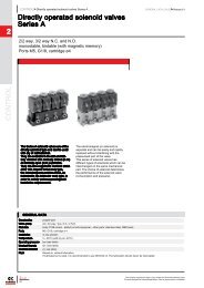
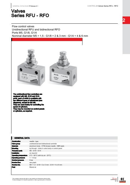
GENERAL CATALOGUE > Release 8.1ValvesSeries <strong>RFU</strong> - <strong>RFO</strong>CONTROL > Valves Series <strong>RFU</strong> - <strong>RFO</strong>2Flow control <strong>valves</strong>Unidirectional <strong>RFU</strong> and bidirectional <strong>RFO</strong>Ports M5, G1/8, G1/4Nominal diameter M5 = 1,5 - G1/8 = 2 & 3 mm - G1/4 = 4 & 6 mmThe unidirectional flow controllers areequipped with M5, G1/8 and G1/4ports, each of which is available withtwo different types of adjustment (seediagrams), except for the M5.They are used mainly for controlling thespeed of cylinders.They may be mounted on control panelsor cylinders, as required.GENERAL DATAConstructionneedle - typeValve groupunidirectional and bidirectional controllerMaterialsaluminium body - OT58 (brass) needle - NBR sealsMountingby through - holes in valve body or control panelThreaded ports M5 - G1/8 - G1/4Installationas requiredOperating temperature 0°C ÷ 80°C (with dry air - 20°C)Operating pressure 1 ÷ 10 barNominal pressure 6 barNominal flowsee graphNominal dia.M5 = 1,5 - G1/8 = 2 or 3 mm - G1/4 = 4 or 6 mmFluidfiltered airThe company reserves the right to vary models and dimensions without notice.Products designed for industrial applications. Sale to general public is forbidden.2/7.2001
CONTROL > Valves Series <strong>RFU</strong> - <strong>RFO</strong>GENERAL CATALOGUE > Release 8.1CODING EXAMPLE2RF U4 8 2<strong>RFU</strong>482SERIES:RFFUNCTION:U4 = unidirectionalO3 = bidirectionalPORTS:8 = G1/84 = G1/45 = M5FLOW CONTROL RANGE:2 = ø 2 max3 = ø 3 max4 = ø 4 max6 = ø 6 maxCONTROLTo ensure the right choice of unidirectional flow controller, proceed as follows: calculate the quantity of air in Nl/min (see cylinderTable); determine the stroke time of the cylinder; refer to graph to see which controller is the right type.6512 UNIDIRECTIONAL AND BIDIRECTIONAL FLOW CONTROLLERSMOUNTING EXAMPLES <strong>RFU</strong> 452-M5 - <strong>RFO</strong> 352-M5Mod. <strong>RFU</strong> - 452 flow from 2 → 1 needle type OPEN = 55 Nl/minCLOSED = 41 Nl/min2/7.2002The company reserves the right to vary models and dimensions without notice.Products designed for industrial applications. Sale to general public is forbidden.
GENERAL CATALOGUE > Release 8.1CONTROL > Valves Series <strong>RFU</strong> - <strong>RFO</strong>UNIDIRECTIONAL AND BIDIRECTIONAL FLOW CONTROLLERS2<strong>RFU</strong> 482-1/8 - <strong>RFU</strong> 483-1/8Mod. <strong>RFU</strong> 482 flow from 2 → 1 needle type OPEN = 149 Nl/minCLOSED = 130,5 Nl/minMod. <strong>RFU</strong> 483 flow from 2 → 1 needle type OPEN = 180 Nl/minCLOSED = 140 Nl/minNB: Qn is determined with a pressure of 6 bar at the inletand ΔP = 1 bar at the outlet.N° = number of screw turns.<strong>RFO</strong> 382-1/8 - <strong>RFO</strong> 383-1/8NB: Qn is determined with a pressure of 6 bar at the inlet and ΔP= 1 bar at the outlet.N° = number of screw turns.UNIDIRECTIONAL AND BIDIRECTIONAL FLOW CONTROLLERS<strong>RFU</strong> 444-1/4 - <strong>RFU</strong> 446-1/4Mod. <strong>RFU</strong> 444 flow from 2 → 1 needle type OPEN = 680 Nl/minCLOSED = 534 Nl/minMod. <strong>RFU</strong> 446 flow from 2 → 1 needle type OPEN = 680 Nl/minCLOSED = 534 Nl/minNB: Qn is determined with a pressure of 6 bar at the inlet and ΔP= 1 bar at the outlet.N° = number of screw turns<strong>RFO</strong> 344-1/4 - <strong>RFO</strong> 346-1/4NB: Qn is determined with a pressure of 6 bar at the inlet and ΔP= 1 bar at the outlet.N° = number of screw turns.The company reserves the right to vary models and dimensions without notice.Products designed for industrial applications. Sale to general public is forbidden.2/7.2003
CONTROL > Valves Series <strong>RFU</strong> - <strong>RFO</strong>GENERAL CATALOGUE > Release 8.1Unidirectional flow controller Series <strong>RFU</strong>2To regulate the speed of a cylinder, the air flow fromthe chamber which is being discharged must beregulated.For this reason, the unidirectional flow controllermust be connected as follows:- connect the threaded outlet marked 1 to thecylinder inlet- connect the threaded outlet marked 2 to the valveuser port.CONTROLDIMENSIONSMod. N Ø A B D F G L M1 M2 M3 T Z S MaxSW SW1 SW2<strong>RFU</strong> 452-M5 1,5 M10x1 M5 4,2 14 16 26 18,5 13,2 7 39 44,5 3 12 14 8<strong>RFU</strong> 482-1/8 2 M12x1 G1/8 4,5 16 21 34 24,5 16,5 8 46 51 4 14 17 9<strong>RFU</strong> 483-1/8 3 M12x1 G1/8 4,5 16 21 34 24,5 16,5 8 46 51 4 14 17 9<strong>RFU</strong> 444-1/4 4 M20x1,5 G1/4 6,5 25 25 52 35 24 12 60 69 7 22 24 14<strong>RFU</strong> 446-1/4 6 M20x1,5 G1/4 6,5 25 25 52 35 24 12 60 69 7 22 24 14Bidirectional flow controller Series <strong>RFO</strong>The bidirectional flow controller is suitable forregulating the air flow in both directions and forpressurising or depressurising containers.When choosing the model, reference must alwaysbe made to the M5, G1/8 and G1/4 graph, althoughit is necessary to know in advance the number oflitres of air to be regulated per unit of time.DIMENSIONSMod. N Ø A B D F G L M1 M2 M3 T Z S MaxSW SW1 SW2<strong>RFO</strong> 352-M5 1,5 M10x1 M5 4,2 14 16 26 18,5 13,2 7 39 44,5 3 12 14 8<strong>RFO</strong> 382-1/8 2 M12x1 G1/8 4,2 16 21 34 24,5 16,5 8 46 51 4 14 17 9<strong>RFO</strong> 383-1/8 3 M12x1 G1/8 4,5 16 21 34 24,5 16,5 8 46 51 4 14 17 9<strong>RFO</strong> 344-1/4 4 M20x1,5 G1/4 6,5 25 30 52 35 24 12 60 69 7 22 24 14<strong>RFO</strong> 346-1/4 6 M20x1,5 G1/4 6,5 25 30 52 35 24 12 60 69 7 22 24 142/7.2004The company reserves the right to vary models and dimensions without notice.Products designed for industrial applications. Sale to general public is forbidden.