4SA0/4SB0 Series
4SA0/4SB0 Series
4SA0/4SB0 Series
- No tags were found...

Create successful ePaper yourself
Turn your PDF publications into a flip-book with our unique Google optimized e-Paper software.
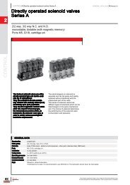
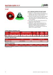
<strong>4SA0</strong>/<strong>4SB0</strong>Small pneumatic valve5 port pilot operated valveMN3E0MN4E04GA/BM4GA/BMN4GA/BOverviewThe <strong>4SA0</strong> and <strong>4SB0</strong> <strong>Series</strong>miniature 5 port valve contributes tospace-saving and weight reduction.This series is compatible for drivingcylinders up to ø25.FeaturesSpace savingThe compact design has 10 mmvalve width.Device weight reducingAluminum and resin areadopted for main components.Energy savingLow wattage design(25 mA at 24 VDC).Wide variation of electric connectionThe lead wire type, C/D-typeconnector are available in thisseries. Lights and surgesuppressors can also becombined.Couple with electronic control5 VDC, 6 VDC, 12 VDC and 24VDC voltages are availablewith a low-wattage design. (25mA at 24 VDC)Resource savingSpecial soft packing seal isadopted, enabling use in an oilfreeenvironment.Compatible with linessusceptible to copperThrough ideal materialselection and special surfacetreatment, the generation ofcopper ion is prevented.Reduced wiring for PLCcontrolThe flat cable connection andD sub-connector connections(radial, axial) are available asconnection types. Reducedwiring can be applied to PLCcontrol.Refer to the safety precautions on Introduction before starting use.C O N T E N T S<strong>Series</strong> variation 704Variation of electric connection (electric connection method / circuit diagram) 706Discrete valve Body porting (<strong>4SA0</strong>) 708 Sub-plate porting (<strong>4SB0</strong>) 708Individual wiring manifold Body porting (M<strong>4SA0</strong>) 716 Sub-plate porting (M<strong>4SB0</strong>) 716Reduced wiring manifold Sub-plate porting (M<strong>4SB0</strong>) 720Technical data(1) Notes when wiring 724(2) Pneumatics system selection guide 7284GA/B(Master)W4GA/B2W4GB4MN3S0MN4S04TB4L2-4/LMF04SA/B04SA/B14KA/B4FPV5G/CMFPV5/CMF3MA/B03PA/BP/M/BNP/NAP/NVP4F*0EHMVHSV2QV3QV703SKHPCD/FS/FDEnding5 port pilot operated valve
<strong>Series</strong> variation<strong>4SA0</strong>/<strong>4SB0</strong> <strong>Series</strong>MN3E0MN4E04GA/BM4GA/BValve performanceMN4GA/B4GA/B(Master)W4GA/B2W4GB4<strong>Series</strong> and piping methodNo. ofportPositionNo. of solenoidJIS symbolEffectivesectionalareaSFlowcharacteristicsC(dm 3 / (s·bar))ApplicablecylinderDiameterVoltageVMN3S0MN4S0(mm 2 )Note 14TB4L2-4/LMF0<strong>4SA0</strong>2-position single solenoid4SA/B04SA/B14KA/B4FPV5G/CMFPV5/CMF3MA/B0DiscreteBody portingSub-plate porting<strong>4SB0</strong>a A BR1 P R22-position double solenoida A B bR1 P R20.90.29to0.3324 DC12 DCOption6 DC5 DC3PA/BP/M/BNP/NAP/NVP4F*0EHMVHSV2QV3QVSKHIndividual wiring manifoldBody portingSub-plate portingM<strong>4SA0</strong>M<strong>4SB0</strong>5 port3-position all ports closeda A B bR1 P R23-position A/B/R connectiona A B bR1 P R20.90.29to0.32ø6toø2524 DC12 DCOption6 DC5 DCPCD/FS/FDEndingReduced wiring manifoldSub-plate portingM<strong>4SB0</strong>3-position P/A/B connectiona A B bR1 P R20.29to0.3224 DC12 DCOption6 DC5 DCNote 1: Effective sectional area S and sonic conductance C are converted as S 5.0 x C.704
<strong>4SA0</strong>/<strong>4SB0</strong> <strong>Series</strong><strong>Series</strong> variationMN3E0MN4E04GA/BSolenoid position A/B port port size Electric connectionM4GA/BBarbed jointFemale threadMN4GA/B2-position single solenoid2-position double solenoid3-position all ports closed3-position A/B/R connection3-position P/A/B connectionMix manifoldø4 barbed jointø6 barbed jointM3M5ø4 push-in jointGrommet lead wireC-connectorD-connectorD sub-connectorFlat cable connectorPage4GA/B(Master)W4GA/B2W4GB4MN3S0MN4S04TB4L2-4/LMF0 7084SA/B04SA/B14KA/B4F 708PV5G/CMFPV5/CMF3MA/B03PA/B 716P/M/BNP/NAP/NVP4F*0E 716HMVHSV2QV3QVSKHPCD/FS/FDEnding 720Note: Refer to the following page for details on electric connection and other options.5 port pilot operated valve705
<strong>4SA0</strong>/<strong>4SB0</strong> <strong>Series</strong>MN3E0MN4E04GA/BM4GA/BMN4GA/BBlankGrommet lead wireElectric connectionDiscrete valve and individual wiring manifoldDD-connector with lead wireReduced wiring manifoldC4T31D sub-connector axialwith surge suppressor, indicator lightBlankManual overrideNon-locking typePOther optionsMounting plate4GA/B(Master)W4GA/B2Lead wire 300 mm(0.13 mm 2 AWG26)Lead wire lengthD : 300 mmD00 : 500 mmD01 : 1000 mmD02 : 2000 mmPushW4GB4MN3S0MN4S04TB4L2-4/LMF04SA/B0CC-connector with lead wireLead wire lengthC : 300 mmC00 : 500 mmC01 : 1000 mmC02 : 2000 mmD1D-connectorwith socketSocket, crimp terminal attachedD4T30D sub-connector radialwith surge suppressor, indicator lightM1LockingPushTurn(120°)Available onlyfor <strong>4SA0</strong>104SA/B14KA/B4FPV5G/CMFPV5/CMF3MA/B0C1 C-connector with socketSocket, crimp terminal attachedD2D-connector with lead wire,surge suppressor, indicator lightLead wire lengthD2 : 300 mmD20 : 500 mmD21 : 1000 mmD22 : 2000 mmRed+Black-C4T50Flat cable connectorwith surge suppressor, indicator light3PA/BP/M/BNP/NAP/NVP4F*0EHMVHSV2QV3QVSKHPCD/FS/FDEndingC2C2NC-connector with lead wire,with surge suppressor, indicator lightLead wire lengthC2 : 300 mmC20 : 500 mmC21 : 1000 mmC22 : 2000 mmBlack-Red+C-connectorwith surge suppressor, indicator lightD2ND3D-connectorwith surge suppressor, indicator lightD-connector with socketwith surge suppressor, indicator lightSocket· Crimp terminal attached+-C-connector with socket,C3with surge suppressor, indicator lightSocket· Crimp terminal attached +Surge suppressor / indicator light internal circuit diagram( + ) Red-( - ) Black* Note that surge suppressor / indicator light has polarity.* Diode is used for surge suppressor.706
MN3E0MN4E04GA/BM4GA/BMN4GA/B4GA/B(Master)W4GA/B2W4GB4MN3S0MN4S04TB4L2-4/LMF04SA/B04SA/B14KA/B4FPV5G/CMFPV5/CMF3MA/B03PA/BP/M/BNP/NAP/NVP4F*0EHMVHSV2QV3QVSKHPCD/FS/FDJIS symbol5 port valve2-position single solenoidaA B2-position double solenoida3-positionAll ports closeda3-position A/B/R connectiona3-position P/A/B connectionaR1 P R2A BR1 P R2A BR1 P R2A BR1 P R2A BR1 P R2bbbbDiscrete5 port pilot operated small pneumatic control valveBody porting, sub-plate portingCommon specificationsDescriptionsValve and operation typeWorking fluidMax. working pressure MPaPilot operated soft spool valveCompressed air0.7Min. working pressure MPa0.2Withstanding pressure MPaAmbient temperature °C1.055 to 50Fluid temperature °C5 to 50LubricationNot requiredProtective structureDust proofVibration/impact m/s 2 50 or less / 300 or lessWorking environment Containing corrosive gas is impermissible.Individual specifications<strong>4SA0</strong>/<strong>4SB0</strong> <strong>Series</strong>Applicable cylinder bore size: ø6 to ø25DescriptionsP/A/B portPort sizeR1/R2 portResponse time 2-positionNote 3 ms 3-positionSingle solenoid2-positionWeight g Double solenoid3-positionM3Electric specificationsDescriptionsRated voltage VRated voltage fluctuation rangeRated current ANote 1Power consumption W Note 2Heat proof classTemperature rise °C<strong>4SA0</strong>Refer to Intro 17 fordetails.ø4 barbed jointM320 or less30 or less23353924 DC0.025(0.029)0.6 (0.7)+ -- 10%B50<strong>4SB0</strong>M5M512 DC0.050(0.058)0.6 (0.7)Note 1: Value in ( ) are for types with light and surge suppressor.Note 2: Power consumption of 6/5 VDC is 0.9 (1.0) W.Note 3: Response time is the value when ON for supply pressure 0.5 MPa, pre-lubricated. The value varies depending on pressure and quality of lubricant.Flow characteristicsModel no.Solenoid positionPort sizeC (dm 3 / (s·bar))P —› A/B2-position- -P/A/B port:All ports closed- -<strong>4SA0</strong>M3, ø4 barbed joint3-position A/B/R connection- -R1/R2 port: M3P/A/B connection- -2-position0.32 0.20All ports closed0.32 0.19<strong>4SB0</strong>M53-position A/B/R connection0.31 0.18P/A/B connection0.33 0.20Note 4: Effective sectional area S and sonic conductance C are converted as S 5.0 x C.bC (dm 3 / (s·bar))----0.300.290.290.29435559A/B —› Rb----0.210.110.220.21S (mm 2 )0.9----EndingOzone specifications(Ending 5)** VoltageP11708
<strong>4SA0</strong>/<strong>4SB0</strong> <strong>Series</strong>Discrete valveMN3E0MN4E04GA/BM4GA/BHow to order discrete valve<strong>4SA0</strong> 1 0 M3 M1 C2 3MN4GA/B4GA/B(Master)W4GA/B2A Model no.ConstantB Solenoid positionC Port sizeD Manual overrideNote on model no. selectionNote 1: The following CKD joints are M3compatible.FTS4-M3, GWS3-M3-SNote 2: With T4, the barbed joint FTS4-M3 isscrewed into the A and B ports.Note 3: AWG26 size lead wire is used. (7/0.16,outer diameter ø1.35, 0.13 mm 2 )E Electric connectionNote 3Note: Refer to page 706 for circuit diagramof surge suppressor and light.F Other options<strong>4SA0</strong>10-M3-M1P-3A Model: <strong>4SA0</strong>B Solenoid position : 2-position single solenoidG VoltageC Port size : M3D Manual override : Lock type manual overrideE Electric connection : Grommet lead wire (standard)F Other options : Mounting plateG Voltage : 24 VDCSymbol DescriptionsB Solenoid position123452-position single solenoid2-position double solenoid3-position all ports closed3-position A/B/R connection3-position P/A/B connectionC Port sizePort P/A/BR1/R2M3M3M5M5T4 ø4 barbed joint M3D Manual overrideBlank Non-locking manual overrideM1 Locking manual overrideE Electric connectionGrommet lead wireBlank Grommet lead wire (300 mm)C-connector (lateral lead wire)C Lead wire (300 mm)C00 Lead wire (500 mm)C01 Lead wire (1000 mm)C02 Lead wire (2000 mm)C1 No lead wire (with socket)C2 Lead wire (300 mm) With surge suppressor and lightC20 Lead wire (500 mm) With surge suppressor and lightC21 Lead wire (1000 mm) With surge suppressor and lightC22 Lead wire (2000 mm) With surge suppressor and lightC2N No lead wire (without socket) With surge suppressor and lightC3 No lead wire (with socket) With surge suppressor and lightD-connector (upward lead wire)DD00D01D02D1D2D20D21D22D2ND3BlankPG34DC6VDC5VLead wire (300 mm)Lead wire (500 mm)Lead wire (1000 mm)Lead wire (2000 mm)No lead wire (with socket)Lead wire (300 mm)Lead wire (500 mm)Lead wire (1000 mm)Lead wire (2000 mm)No lead wire (without socket)No lead wire (with socket)F Other optionsWithout mounting plateMounting plate (only 2-position single)VoltageStandardOption24 VDC12 VDC6 VDC5 VDCWith surge suppressor and lightWith surge suppressor and lightWith surge suppressor and lightWith surge suppressor and lightWith surge suppressor and lightWith surge suppressor and lightABodyporting<strong>4SA0</strong>Model no.Note 1Note 2Sub-plateporting<strong>4SB0</strong>W4GB4MN3S0MN4S04TB4L2-4/LMF04SA/B04SA/B14KA/B4FPV5G/CMFPV5/CMF3MA/B03PA/BP/M/BNP/NAP/NVP4F*0EHMVHSV2QV3QVSKHPCD/FS/FDEndingDiscrete5 port pilot operated valve709
MN3E0MN4E04GA/B<strong>4SA0</strong> <strong>Series</strong>Discrete valve: Body portingInternal structure and parts list<strong>4SA0</strong>102-position single solenoidM4GA/BMN4GA/BaA BSOL (a)8 7 5 3 4 1 6 24GA/B(Master)R1 P R2W4GA/B2W4GB4MN3S0MN4S04TB4L2-4/LMF04SA/B0<strong>4SA0</strong>202-position double solenoida A B bSOL (a)8 7 5 3 4 1 3 5 7 8SOL (b)4SA/B1R1 P R24KA/B4FPV5G/CMFPV5/CMF3MA/B03PA/BP/M/BNP/NAP/NVP4F*0EHMVHSV2QV3QVSKHPCD/FS/FDEnding<strong>4SA0</strong>303-positionall ports closed<strong>4SA0</strong>40A/B/R connection<strong>4SA0</strong>50P/A/B connectionMain parts listaaaA BR1 P R2A BR1 P R2A BR1 P R2bbbSOL (a)8 7 5 3 4 1 3 5 7 8Repair parts listNo. Parts name Material No. Parts name Model no.12345678Spool assemblyPiston S assemblyPiston D assemblyBodyPiston roomCapManual overrideCoil assembly---AluminumResinResinResin-8 Coil assembly4S0- Electric connection -COIL- VoltageBlank for grommet leadwire.SOL (b)710
Internal structure and parts list<strong>4SB0</strong>102-position single solenoida A BR1 P R2<strong>4SB0</strong>202-position double solenoida A B bR1 P R2SOL (a)SOL (a)8 7 5 3 4 1 6 28R1PR27 5 3 4 1 3 5 7 89SOL (b)<strong>4SB0</strong> <strong>Series</strong>Discrete valve: Sub-plate portingMN3E0MN4E04GA/BM4GA/BMN4GA/B4GA/B(Master)W4GA/B2W4GB4MN3S0MN4S04TB4L2-4/LMF04SA/B04SA/B1<strong>4SB0</strong>303-positionall ports closed<strong>4SB0</strong>40A/B/R connection<strong>4SB0</strong>50123456789P/A/B connectionMain parts listRepair parts listNo. Parts name Material No. Parts name Model no.Spool assemblyPiston S assemblyPiston D assemblyBodyPiston roomCapManual overrideCoil assemblySub-plateaaaA BR1 P R2A BR1 P R2A BR1 P R2bbb---AluminumResinResinResin-AluminumSOL (a)8R1PR27 5 3 4 1 3 5 7R1PR299SOL (b)4S0- Electric connection -COIL- Voltage8 Coil assemblyBlank for grommet leadwire.84KA/B4FPV5G/CMFPV5/CMF3MA/B03PA/BP/M/BNP/NAP/NVP4F*0EHMVHSV2QV3QVSKHPCD/FS/FDEndingDiscrete5 port pilot operated valve711
MN3E0MN4E04GA/B<strong>4SA0</strong> <strong>Series</strong>Discrete valve: Body portingDimensions<strong>4SA0</strong>10-M32-position single solenoid: Grommet lead wire<strong>4SA0</strong>20-M32-position double solenoid: Grommet lead wireM4GA/BMN4GA/B4GA/B(Master)2-M3(A/B port)6.9 12.32-ø1.8(Installation hole)4.82-M3(A/B port)6.92-ø1.8(Installation hole)W4GA/B2W4GB4MN3S0MN4S0Lead wire 300 m(AWG26)Manual overrideAB10.3 10.5327.4Lead wire 300 m(AWG26)Manual override7.4A10.332.5B4.84TB4L2-4/LMF04SA/B02421.56.437532.5131421.52-ø2.1(Installation hole)2421.52.5376.4742-ø2.1(Installation hole)4SA/B115.74KA/B10104FPV5G/CMFPV5/CMF6.9 6.93-M3(R1/P/R2 port)6.9 6.93-M3(R1/P/R2 port)3MA/B03PA/BMounting plate: P (only 2-position single solenoid)3<strong>4SA0</strong>40-M353-position: Grommet lead wireP/M/BNP/NAP/NVP4F*0EHMVHSV2QV3QVSKHPCD/FS/FDEnding2.0 102-ø3.5(Installation hole)Non-locking typeManual override222-M3(A/B port)Lead wire 300 m(AWG26)Manual override2.5376.910.3396.4812-ø1.8(Installation hole)4.82-ø2.1(Installation hole)102421.57.4AB6.9 6.93-M3(R1/P/R2 port)712
<strong>4SA0</strong> <strong>Series</strong>Discrete valve: Body portingDimensionsø4 barbed joint: (T4)Locking manual override: (M1)MN3E0MN4E04GA/BM4GA/B0.8 slitMN4GA/B24208120°4GA/B(Master)ø5.2W4GA/B2242024W4GB4MN3S0MN4S04TB4L2-4/LMF04SA/B04SA/B14KA/B4FPV5G/CMFPV5/CMF3MA/B03PA/BP/M/BNP/NAP/NVP4F*0EHMVHSV2QV3QVSKHPCD/FS/FDEndingDiscrete5 port pilot operated valve830ø4 barbed joint3-FTS4-M3 (P/A/B port)C-connector: (C/C0*/C1/C2/C2*/C3)62469346992420502-position single solenoid 2-position double solenoid 3-positionD-connector: (D/D0*/D1/D2/D2*/D3)57418341893024502-position single solenoid 2-position double solenoid 3-position713
MN3E0MN4E04GA/BM4GA/BMN4GA/B4GA/B(Master)W4GA/B2W4GB4MN3S0MN4S04TB4L2-4/LMF04SA/B0<strong>4SB0</strong> <strong>Series</strong>Discrete valve: Sub-plate portingDimensions<strong>4SB0</strong>10-M52-M5(A/B port)2-ø3.2(Installation hole)Manual overrideLead wire 300 m(AWG26)21.411.732 (discrete base)265332.56392.51118<strong>4SB0</strong>20-M52-position single solenoid: Grommet lead wire 2-position double solenoid: Grommet lead wireAABB2-M5(A/B port)2-ø3.2(Installation hole)Manual overrideLead wire 300 m(AWG26)A21.411.732 (discrete base)26A74B32.5 (manual pitch)B6392.511184SA/B14KA/B38.53614R1PR228.53638.538.53614R1PR2143638.54FPV5G/CMFPV5/CMF3-M5(R1/P/R2 port)10 1015 173MA/B03PA/B63-M5(R1/P/R2 port)3<strong>4SB0</strong>40-M553-position: Grommet lead wire610 1015 17 21P/M/BNP/NAP/NVP2-M5(A/B port)21.411.74F*0E69HMVHSV2QV3QV2-ø3.2(Installation hole)Manual overrideA3226B32.5SKH11PCD/FS/FDEndingLead wire 300 m(AWG26)AB39 (manual pitch)81181438.536R13638.5614PR23-M5(R1/P/R2 port)10 1015 17 28714
<strong>4SB0</strong> <strong>Series</strong>Discrete valve: Sub-plate portingDimensionsLocking manual override: (M1)MN3E0MN4E04GA/BM4GA/B0.8 slit120°ø5.2MN4GA/B4GA/B(Master)W4GA/B2W4GB4242024MN3S0MN4S04TB4L2-4/LMF04SA/B0C-connector: (C/C0*/C1/C2/C2*/C3)4SA/B14KA/B6293994FPV5G/CMF38.534.5R1 P R2R1 P R230R1 P R237PV5/CMF3MA/B03PA/B2-position single solenoid 2-position double solenoid 3-positionP/M/BNP/NAP/NVPD-connector: (D/D0*/D1/D2/D2*/D3)4F*0E578389HMVHSV2QV3QVSKH44.538.5PCD/FS/FDR1PR2R1PR225R1PR232Ending2-position single solenoid 2-position double solenoid 3-positionDiscrete5 port pilot operated valve715
MN3E0MN4E04GA/BM4GA/BIndividual wiring manifold5 port pilot operated small pneumatic control valveBody porting, sub-plate portingM<strong>4SA0</strong>/M<strong>4SB0</strong> <strong>Series</strong>Applicable cylinder bore size: ø6 to ø25Refer to Intro 17 for details.MN4GA/B4GA/B(Master)W4GA/B2W4GB4MN3S0MN4S04TB4L2-4/LMF04SA/B04SA/B14KA/B4FPV5G/CMFPV5/CMF3MA/B03PA/BP/M/BNP/NAP/NVP4F*0EHMVHSV2QV3QVSKHPCD/FS/FDEndingJIS symbol5 port valve2-position single solenoidaA B2-position double solenoida3-positionAll ports closeda3-position A/B/R connectiona3-position P/A/B connectionaR1 P R2A BR1 P R2A BR1 P R2A BR1 P R2A BR1 P R2(Mix manifold)How to Indicate CombinationsWhen selecting a combination manifold (8 selected for"B"), indicate the required functions with symbols (referto right table) and layout number (start with 1 at the leftand assign numbers to the designated number ofstations) in the Remarks field at the bottom of the normalmodel indication. Refer to the example for details.bbbbCommon specificationsDescriptionsManifold methodManifold typeStation numberManifold integratedCommon supply, common exhaust2 to 20 stationsValve and operation typeWorking fluidMax. working pressure MPaPilot operated soft spool valveCompressed air0.7Min. working pressure MPa0.2Withstanding pressure MPaAmbient temperature °C1.055 to 50Fluid temperatureLubrication°C5 to 50Not requiredProtective structure Dust proofVibration/impact m/s 2 50 or less / 300 or lessWorking environment Containing corrosive gas is impermissible.Individual specificationsDescriptionsPort sizeNote 3Response timeNote 4 msSymbolS1S2S3S4S5MPP portA/B portR port2-position3-positionFunction2-position single solenoid2-position double solenoid3-position all ports closed3-position A/B/R connection3-position P/A/B connectionMasking plate1 2 3 4 5 6 72-positionSingle solenoid2-positionDouble solenoid3-positionAll ports closed3-positionAll ports closedElectric specificationsDescriptionsRated voltage VRated voltage fluctuation rangeRated current ANote 1Power consumption W Note 2Heat proof class2-positionDouble solenoid2-positionSingle solenoid3-positionA/B/R connection(S1)(S2)(S3)(S3)(S2)(S1)(S4)24 DC0.025(0.029)0.6 (0.7)+ -- 10%12 DCTemperature rise °C50Note 1: Value in ( ) are for types with light and surge suppressor.Note 2: Power consumption of 6/5 VDC is 0.9 (1.0) W.M<strong>4SA0</strong>M5M3Rc 1/820 or less30 or lessBM<strong>4SB0</strong>M5, Rc1/8M50.050(0.058)0.6 (0.7)Note 3: In addition to the above sizes, optional sizes are available for P and A/B port sizes. Refer to item "C" in the How toorder section on the next page. <strong>4SA0</strong> is a pilot atmospheric release type. Contact CKD for the exhaust common type.With <strong>4SB0</strong>, the pilot exhaust is gathered at the R port.Note 4: Response time is the value when ON for supply pressure 0.5 MPa, pre-lubricated. The value varies depending on pressure and quality of lubricant.Flow characteristicsModel no.M<strong>4SA0</strong>M<strong>4SB0</strong>Solenoid position2-position3-position2-position3-positionPort sizeP port: M5, A/B port: M3R port: Rc1/8P port: M5, Rc1/8A/B port: M5, R port: Rc1/8P —› A/B||0.300.29||0.150.14A/B —› RC (dm 3 / (s·bar)) b C (dm 3 / (s·bar)) b||0.300.30Note 5: When selecting the T4 specifications (using ø4 barbed joint), the flow rate will be restricted by the joint’s effective sectional area.Note 6: Effective sectional area S and sonic conductance C are converted as S 5.0 x C.||0.210.20ExampleThe model number for a combination manifoldwith 7 stations, M5 A/B/P ports, and 24VDCwith the layout shown in the left is as follows:M<strong>4SB0</strong>80-M5-C02-7-3-222100S1=1, 6 S2=2, 5 S3=3, 4 S4=7Symbol PositionWhen using 10 or more actuators of the same model in a mixed manifold, designate with the following symbols.Actuator quantitySymbol10A11B12C13D14E15F16G17H18I19JS1 S2S3 S4S5 MP2 2 2 1 0 0Ozone specifications(Ending 5)** VoltageP11716
M<strong>4SA0</strong>/M<strong>4SB0</strong> <strong>Series</strong>Individual wiring manifoldMN3E0MN4E0How to order individual wiring manifoldDiscrete solenoid valve for manifold (body porting)<strong>4SA0</strong><strong>4SB0</strong>M <strong>4SB0</strong> 8 0 M5 M1 C2 5 3A Model no.Individual wiring manifoldM<strong>4SB0</strong>10-M5-C2-2-31 9 M3 M1 C2 3Discrete solenoid valve for manifold (sub-base porting)Individual wiring manifold1 9 00 M1 C2 3ConstantB Solenoid positionRefer to page 727 for How toorder manifold base and How toorder masking plate.C Port sizeNote on model no. selectionD Manual overrideFor M<strong>4SA0</strong>Note 1: The following CKD joints are M3 compatible.FTS4-M3, GWS3-M3-SNote 2: With T4, the barbed joint FTS4-M3 is screwed into the A and B ports.For M<strong>4SB0</strong>Note 3: With GS4, the push-in joint GWS4-M5-S is screwed intothe A and B ports.Note 4: With T4/T6, FTS4-M5 and FTS6-M5 are screwed intothe A and B ports.A Model no. : M<strong>4SB0</strong>B Solenoid position: 2-position single solenoidC Port size : A/B/P port = M5,R port = Rc1/8D Manual override : Non-locking manual overrideE Electric connection : C-connector with lead wire (300mm), with light and surge suppressorF Station number : 2 stationsG Voltage : 24 VDCE Electric connectionNote Refer to page 706 forcircuit diagram of type withsurge suppressor and light.F Station numberG Voltage2 2 0 0 0 1Indicate the quantity anddisplay position of eachvalve function for themixed manifold.Refer to page 716.Symbol DescriptionsB Solenoid position1 2-position single solenoid2 2-position double solenoid3 3-position all ports closed4 3-position A/B/R connection5 3-position P/A/B connection8 Mix manifoldC Port sizePort A/BM3 M 3M5 M 5GS4 ø4 push-in jointT4 ø4 barbed jointT6 ø6 barbed jointPM5 M 5PGS4 ø4 push-in jointPT4 ø4 barbed jointPT6 ø6 barbed jointD Manual overrideBlankM1PM 5Rc1/8RRc1/8Rc1/8E Electric connectionGrommet lead wireBlank Grommet lead wire (300 mm)C-connector (lateral lead wire)CC00C01C02C1Lead wire (300 mm)Lead wire (500 mm)Lead wire (1000 mm)Lead wire (2000 mm)No lead wire (with socket)C2C20C21C22C2NC3Lead wire (300 mm)Lead wire (500 mm)Lead wire (1000 mm)Lead wire (2000 mm)No lead wire (without socket)No lead wire (with socket)With surge suppressor and lightWith surge suppressor and lightWith surge suppressor and lightWith surge suppressor and lightWith surge suppressor and lightWith surge suppressor and lightD-connector (upward lead wire)DD00D01D02D1D2D20D21D22D2ND3Non-locking manual overrideLocking manual overrideLead wire (300 mm)Lead wire (500 mm)Lead wire (1000 mm)Lead wire (2000 mm)No lead wire (with socket)Lead wire (300 mm)Lead wire (500 mm)Lead wire (1000 mm)Lead wire (2000 mm)No lead wire (without socket)No lead wire (with socket)F Station number2 to 20 2 to 20 stationsG Voltage3 24 VDC4 12 VDCDC6V 6 VDCDC5V 5 VDCStandardOptionWith surge suppressor and lightWith surge suppressor and lightWith surge suppressor and lightWith surge suppressor and lightWith surge suppressor and lightWith surge suppressor and lightABodyporting<strong>4SA0</strong>Model no.Note 1Note 2Sub-plateporting<strong>4SB0</strong>Note 3Note 4Note 4Note 3Note 4Note 44GA/BM4GA/BMN4GA/B4GA/B(Master)W4GA/B2W4GB4MN3S0MN4S04TB4L2-4/LMF04SA/B04SA/B14KA/B4FPV5G/CMFPV5/CMF3MA/B03PA/BP/M/BNP/NAP/NVP4F*0EHMVHSV2QV3QVSKHPCD/FS/FDEndingIndividual wiring manifold5 port pilot operated valve717
MN3E0MN4E04GA/BM4GA/BM<strong>4SA0</strong>/M<strong>4SB0</strong> <strong>Series</strong>Individual wiring manifold: Body porting and sub-plate portingDimensionsM<strong>4SA0</strong>*0-M3Body porting A type: Grommet lead wireMN4GA/B4GA/B(Master)W4GA/B2W4GB4MN3S0MN4S04TB4L2-4/LMF04SA/B04SA/B1Manual override2-ø3.3(Installation hole)2n-M3(A/B port)R PL (10.5 (n - 1) + 26)L1 (10.5 (n - 1) + 19)ABABAB10.5(Pitch)9.5RP213.53655 (single solenoid)74 (double solenoid)81 (3-position)Masking plateLead wire 300 mm(AWG26)4KA/B4FPV5G/CMFPV5/CMF3MA/B03PA/BP/M/BNP/NAP/NVP4F*0EHMVHSV2QV3QVSKHPCD/FS/FDEndingStation number 2 3 4 5 6 7 8 9 10 11 12 13 14 15 16 17 18 19 20L1L4037.524.515.529.536.5M<strong>4SB0</strong>*0-M5404750.557.5616871.578.5828992.599.5103110Sub-plate porting B type (P port M5): Grommet lead wireManual override2-ø4.3(Installation hole)4643.530.521.5R PAL (10.5 (n - 1) + 28)L1 (10.5 (n - 1) + 20)ABABAB10.5(Pitch)14710.5 pitch 11ABRPB444157 (single solenoid)74 (double solenoid)81 (3-position)Masking plate2n-M5(A/B port)5.516113.5120.52-M5(P port)2-Rc1/8(R port) 201241312-M5(P port)2-Rc1/8(R port)134.5141.51451528227155.5162.5101189.5166173176.5183.5187194P port Rc1/8197.5204.52082154-ø4.3(Installation hole)4P R4 21Rc1/8(P port)Lead wire 300 mm(AWG26)BA24.5218.5225.510118.0Station number 2 3 4 5 6 7 8 9 10 11 12 13 14 15 16 17 18 19 20L1L30.538.5414951.559.5627072.580.5839193.5101.5104112114.5122.5125133135.5143.5146154156.5164.5167175177.5185.5188196198.5206.5209217219.5227.5718
M<strong>4SA0</strong>/M<strong>4SB0</strong> <strong>Series</strong>Individual wiring manifold: Body porting and sub-plate portingDimensionsBody porting A typeø4 barbed joint: (T4)8C-connector:(C/C0*/C1/C2/C2*/C3)MN3E0MN4E04GA/BM4GA/B99 (3-position)MN4GA/B92 (double solenoid)62 (single solenoid)4GA/B(Master)W4GA/B23640W4GB43628MN3S0MN4S04TBLocking manual override: (M1)D-connector:(D/D0*/D1/D2/D2*/D3)4L2-4/LMF04SA/B00.8 slit120°89 (3-position)82 (double solenoid)57 (single solenoid)4SA/B14KA/Bø5.24F244046PV5G/CMF3623PV5/CMF3MA/B0ø4 push-in joint: (GS4/PGS4)C-connector:(C/C0*/C1/C2/C2*/C3)3PA/BSub-plate porting B typeP/M/B99 (3-position)92 (double solenoid)62 (single solenoid)NP/NAP/NVP4F*0EHMVHSV42462QV3QV165.514.54125.5SKHPCD/FS/FDø4, ø6 barbed joint:(T4/T6/PT4/PT6)D-connector:(D/D0*/D1/D2/D2*/D3)Ending165.589 (3-position)82 (double solenoid)57 (single solenoid)4652Individual wiring manifold5 port pilot operated valve8 (T4, PT4)10 (T6, PT6)4120.5719
MN3E0MN4E04GA/BM4GA/BReduced wiring manifold5 port pilot operated small pneumatic control valveSub-plate portingM<strong>4SB0</strong> <strong>Series</strong>Applicable cylinder bore size: ø6 to ø25MN4GA/B4GA/B(Master)W4GA/B2W4GB4MN3S0MN4S04TB4L2-4/LMF04SA/B04SA/B14KA/B4FPV5G/CMFPV5/CMF3MA/B03PA/BP/M/BNP/NAP/NVP4F*0EHMVHSV2QV3QVSKHPCD/FS/FDEndingJIS symbol5 port valve2-position single solenoidaA B2-position double solenoida3-positionAll ports closeda3-position A/B/R connectiona3-position P/A/B connectionaR1 P R2A BR1 P R2A BR1 P R2A BR1 P R2A BR1 P R2(Mix manifold)How to Indicate CombinationsWhen selecting a combination manifold (8 selected for"A"), indicate the required functions with symbols (referto right table) and layout number (start with 1 at the leftand assign numbers to the designated number ofstations) in the Remarks field at the bottom of the normalmodel indication. Refer to the example for details.bbbbCommon specificationsDescriptionsManifold methodManifold typeStation numberValve and operation typeWorking fluidMax. working pressure MPaManifold integratedCommon supply, common exhaust2 to 20 stationsPilot operated soft spool valveCompressed air0.7Min. working pressure MPa0.2Withstanding pressure MPaAmbient temperature °C1.055 to 50Fluid temperature °C5 to 50LubricationProtective structureNot requiredDust proofVibration/impact m/s 2 50 or less / 300 or lessWorking environment Containing corrosive gas is impermissible.Individual specificationsDescriptionsPort sizeNote 2Response timeNote 3 msSymbolS1S2S3S4S5MPP portA/B portR port2-position3-positionFunction2-position single solenoid2-position double solenoid3-position all ports closed3-position A/B/R connection3-position P/A/B connectionMasking plate1 2 3 4 5 6 72-positionSingle solenoid2-positionDouble solenoid3-positionAll ports closed3-positionAll ports closedElectric specificationsDescriptionsRated voltage V 24 DC 12 DCRated voltage fluctuation range+ -- 10%Rated current A 0.029 0.058Power consumption W Note 1 0.70.7Heat proof classTemperature rise °CB50Note 1: Power consumption of 6/5 VDC is 1.0 W.2-positionDouble solenoid2-positionSingle solenoid3-positionA/B/R connectioniS1 jiS2 jiS3 jiS3 jiS2 jiS1 jiS4 jM<strong>4SB0</strong>M5, Rc1/8M5Rc1/820 or less30 or lessNote 2: In addition to the above sizes, optional sizes are available for the P and A/B port. Refer to item "B" in the How to ordersection on the next page. With <strong>4SB0</strong>, the pilot exhaust is gathered at the R port.Note 3: Response time is the value when ON for supply pressure 0.5 MPa, pre-lubricated. The value varies depending on pressure and quality of lubricant.Flow characteristicsModel no. Solenoid positionPort size C (dm 3 / (s·bar)) b2-positionP port: M5, Rc1/80.300.15M<strong>4SB0</strong>3-positionA/B port: M5, R port: Rc1/80.290.14Note 4: When selecting the T4 specifications (using ø4 barbed joint), the flow rate will be restricted by the joint’s effective sectional area.Note 5: Effective sectional area S and sonic conductance C are converted as S 5.0 x C.ExampleThe model number for a combination manifoldwith 7 stations, M5 A/B/P ports, and 24VDCwith the layout shown in the left is as follows:M<strong>4SB0</strong>80-M5-C4T50-7-3-222100S1=1, 6 S2=2, 5 S3=3, 4 S4=7Symbol PositionWhen using 10 or more actuators of the same model in a mixed manifold, designate with the following symbols.Actuator quantitySymbol10A11B12C13D14E15F16G17H18I19JS1 S2S3 S4S5 MP2 2 2 1 0 0Ozone specifications(Ending 5)** VoltageP11720
M<strong>4SB0</strong> <strong>Series</strong>Reduced wiring manifold: Sub-plate portingMN3E0MN4E0How to order reduced wiring manifoldDiscrete solenoid valve for manifold (sub-plate porting)<strong>4SB0</strong>Reduced wiring manifoldM <strong>4SB0</strong> 8 0 M5 M1 C4T31 5 3Model no.ConstantA Solenoid positionRefer to page 727 for How toorder manifold base and How toorder masking plate.Refer to page 725 for D-subcablewith connector model no.Refer to page 727 for cablemodel no. for a flat cableconnector.1 9 00 M1 C2 3B Port sizeNote on model no. selectionC Manual overrideNote 1: With GS4, the push-in joint GWS4-M5-S is screwed intothe A and B ports.Note 2: With T4/T6, FTS4-M5 and FTS6-M5 are screwed into theA and B ports.Note 3: With C4 and D4, only the discrete solenoid valve for <strong>4SB0</strong>manifold is available.The reduced-wiring socket assembly (lead wire length 270 mm) is enclosed.Note 4: With T30/T31, up to 20 single solenoid stations can be used.With T50, up to 16 single solenoid stations can be used.D Electric connectionNote Refer to page 706 forcircuit diagram of type withsurge suppressor and light.E Station numberF Voltage2 2 0 0 0 1SymbolDescriptionsA Solenoid position1234582-position single solenoid2-position double solenoid3-position all ports closed3-position A/B/R connection3-position P/A/B connectionMix manifoldB Port sizePortM5A/BM5PRGS4 ø4 push-in joint Note 1T4 ø4 barbed joint Note 2M 5 Rc 1/8T6 ø6 barbed joint Note 2PM5 M5PGS4 ø4 push-in joint Note 1PT4 ø4 barbed joint Note 2Rc 1/8 Rc 1/8PT6 ø6 barbed joint Note 2C Manual overrideBlankM1Non-locking manual overrideLocking manual overrideD Electric connectionC4D4C4T31D4T30C4T50C-connector (T31/T50) Note 3D-connector (T30) Note 3D sub-connector lateralD sub-connector upwardFlat cable connector typeWith surge suppressor and lightWith surge suppressor and lightWith surge suppressor and lightWith surge suppressor and lightWith surge suppressor and lightE Station number4 to 20 4 to 20 stations Note 4F Voltage34DC6VDC5V24 VDC12 VDC6 VDC5 VDCStandardOptionIndicate the quantity and display position of eachvalve function for the mixed manifold.Refer to page 720.4GA/BM4GA/BMN4GA/B4GA/B(Master)W4GA/B2W4GB4MN3S0MN4S04TB4L2-4/LMF04SA/B04SA/B14KA/B4FPV5G/CMFPV5/CMF3MA/B03PA/BP/M/BNP/NAP/NVP4F*0EHMVHSV2QV3QVSKHPCD/FS/FDEndingReduced wiring manifoldM<strong>4SB0</strong>10-M5-C4T50-7-3Model : M<strong>4SB0</strong>A Solenoid position : 2-position single solenoidB Port size : A/B/P port = M5,R port = Rc1/8C Manual override : Non-locking manual overrideD Electric connection : Flat cable connector typeE Station number : 7 stationsF Voltage: 24VDC721Reduced wiring manifold5 port pilot operated valve
MN3E0MN4E04GA/BM4GA/BM<strong>4SB0</strong> <strong>Series</strong>Reduced wiring manifold: Sub-plate portingDimensionsM<strong>4SB0</strong>*0-M5-D4T30D sub-connector upward: (P port M5)11974M2.6 x 0.45MN4GA/B84GA/B(Master)W4GA/B2W4GB4MN3S0MN4S0Manual override414R PABABABABABABABABRP85 (single solenoid)107 (double solenoid)113 (3-position)4TB4L2-4/LMF04SA/B02-ø4.3(Installation hole)4L1 (10.5 x (n - 1) + 20)L (10.5 x (n - 1) + 28)4SA/B1Masking plate4KA/B54.54FPV5G/CMFPV5/CMF3MA/B03PA/B24M<strong>4SB0</strong>*0-M5-C4T31D sub-connector lateral: (P port M5)11974A7B818.513.512.511 810.5 pitch22 44M2.6 x 0.4520P/M/B5.8NP/NAP/NVP4F*0EHMVHSV2QV3QVManual override414R PABABABABABABABABP R91 (single solenoid)118 (double solenoid)124 (3-position)SKHPCD/FS/FDEnding4L1 (10.5 x (n - 1) + 20)L (10.5 x (n - 1) + 28)Masking plate48.5B24A10.5 pitch711818.513.512.5822 501220722Station number 4 5 6 7 8 9 10 11 12 13 14 15 16 17 18 19 20L1L51.559.5627072.580.5839193.5101.5104112114.5122.5125133135.5143.5146154156.5164.5167175177.5185.5188196198.5206.5209217219.5227.5
DimensionsA/B port M5, P port 1/8:(PM5)ø4 push-in joint: (GS4/PGS4)M<strong>4SB0</strong> <strong>Series</strong>Reduced wiring manifold: Sub-plate portingø4, ø6 barbed joint:(T4/T6/PT4/PT6)MN3E0MN4E04GA/BM4GA/BMN4GA/B4GA/B(Master)4-ø4.5(Installation hole)44BP21ARW4GA/B2W4GB4MN3S0MN4S04TB4L2-4/LMF0Rc1/8(P port)24.512.513.58.018.5815.518.588 (T4, PT4)10 (T6, PT6)4SA/B04SA/B14KA/B4FM<strong>4SB0</strong>*0-M5-C4T50Flat cable connector type: (P port M5)1197416.5PV5G/CMFPV5/CMF3MA/B03PA/BP/M/BManual override414R PABABABABABABABABRP102 (single solenoid)128.5 (double solenoid)135.5 (3-position)NP/NAP/NVP4F*0EHMVHSV2QV3QVSKH2-ø4.3(Installation hole)PCD/FS/FD4L1 (10.5 x (n - 1) + 20)L (10.5 x (n - 1) + 28)Ending48.524A10.5 pitch711Masking plateB818.513.512.52-M5 (P port)82-Rc1/8 (R port) 226112.5Reduced wiring manifold5 port pilot operated valveStation numberL1L451.559.556270672.580.578391893.5101.5910411210114.5122.51112513312135.5143.51314615414156.5164.51516717516177.5185.5723
<strong>4SA0</strong>/<strong>4SB0</strong> <strong>Series</strong>MN3E0MN4E0Technical data1Notes when wiring: D sub-connector type4GA/BD sub-connector type: Wiring method T30/T31M4GA/BMN4GA/B4GA/B(Master)W4GA/B2W4GB4MN3S0MN4S0T30, T31 connectorConnectors used for T30/T31 wiring method aregenerally called D-sub connectors. These are commonlyused for FA and OA devices. The 25P type is theconnector designated in RS-232-C Standards that applyto personal computer communication functions. Themanifold stations are set in order from the left with the bside solenoid (cap side for single) facing forward.R PABABABABABABABABRP4TB4L2-4/LMF04SA/B04SA/B14KA/B4FPV5G/CMFPV5/CMF3MA/B03PA/BCautions for connector type T30/T311234The PC output unit's signal array and valve signalarray must match.The working power is 12/24 VDC dedicated.The voltage could drop because of simultaneousenergizing or the cable length. Confirm that the voltagedrop for the solenoid is within 10% of the rated voltage.This is +COM specifications.Station no. 1nth station 2nth station 3nth station n-th station11421531641751861972082192210231124122513COM (+)(Internal circuit)NO1142153164175186197208219221023P/M/BNP/NAP/NVP4F*0EHMVHSV2QV3QVSKHT30/T31 connector pin array (example)Note: The numbers in the valve No. 1a, 1b, 2a, 2b and so forth indicate the first station and 2nd station.The alphabetic characters a and b indicate the a side solenoid and the b side solenoid.1 2 3 4 5 6 7 8 9 10 11 12 1314 15 16 17 18 19 20 21 22 23 24 25PCD/FS/FDEndingFor single solenoid valve(Available up to 20 stations)Pin No.Valve No.Pin No.Valve No.11a142a23a154a35a166a47a178a59a1810a611a1912a713a2014a815a2116a917a2218a1019a2320a1124122513COM (+)For double solenoid valve(Available up to 10 stations)Pin No.Valve No.Pin No.Valve No.11a141b22a152b33a163b44a174b55a185b66a196b77a207b88a218b99a229b1010a2310b1124122513COM (+)For mix (single and double mixture)(Available up to 20 solenoids)Pin No.Valve No.Pin No.Valve No.11a142a23a153b34a164b45a176a57a187b68a199a710a2011a811b2112a912b2213a1014a2315a1124122513COM (+)724
How to order cable with D-sub connectorN4T CABLE D 0 0 1<strong>4SA0</strong>/<strong>4SB0</strong> <strong>Series</strong>Technical data 1 Notes when wiring: D sub-connector* Pneumatic valvesCompatible with D-sub connector T30/T31MN3E0MN4E04GA/BAUser interfaceBCable lengthCorrespondence of D-sub connector terminal No. and conductorN4T-CABLE-D00- BHDBB-25SHIROSE ELECTRIC CO. LTD.ABMulti conductor cable(UL-2464-SB-13P24AWG)SymbolUser interface01Cable length135ModelN4TCut onlyWith round terminal for M3.5 screw1 m3 m5 mM4GA/BMN4GA/B4GA/B(Master)W4GA/B2W4GB4MN3S0MN4S04TB4L2-4/LMF04SA/B04SA/B14KA/B4FD sub-connector terminal No.Isolator colorConductor I.D. Mark typeMark colorD sub-connector terminal No.Isolator colorConductor I.D. Mark typeMark colorN4T-CABLE-D01- B1 2 3 4 5Orange Orange Yellow Yellow Green1 point 1 point 1 point 1 point 1 pointBlack Red Black Red Black14 15 16 17 18Yellow Green Green Gray Gray2 points 2 points 2 points 2 points 2 pointsRed Black Red Black RedHDBB-25SHIROSE ELECTRIC CO. LTD.Cable lengthMulti conductor cable(UL2464-SB-13P24AWG)6Green1 pointRed19White2 pointsBlackCable length 1007Gray1 pointBlack20White2 pointsRed8 9 10 11 12Gray White White Orange Orange1 point 1 point 1 point 2 points 2 pointsRed Black Red Black Red21 22 23 24 25Orange Orange Yellow Yellow Green3 points 3 points 3 points 3 points 3 pointsBlack Red Black Red BlackRound crimp terminal(1.25-3.5)13Yellow2 pointsBlackPV5G/CMFPV5/CMF3MA/B03PA/BP/M/BNP/NAP/NVP4F*0EHMVHSV2QV3QVSKHPCD/FS/FDEndingD sub-connector terminal No.Isolator colorConductor I.D. Mark typeMark colorMark tube No.D sub-connector terminal No.Isolator colorConductor I.D. Mark typeMark colorMark tube No.1Orange1 pointBlack12Orange1 pointRed23Yellow1 pointBlack314 15 16Yellow Green Green2 points 2 points 2 pointsRed14Black15Red16* Up to 24 points can be used. Cut off any excessive points before using.4Yellow1 pointRed417Gray2 pointsBlack175Green1 pointBlack518Gray2 pointsRed186Green1 pointRed619White2 pointsBlack197Gray1 pointBlack720White2 pointsRed208Gray1 pointRed89White1 pointBlack910White1 pointRed1011 12Orange Orange2 points 2 pointsBlack Red11 1221 22 23 24 25Orange Orange Yellow Yellow Green3 points 3 points 3 points 3 points 3 pointsBlack21Red22Black23Red24Black2513Yellow2 pointsBlack137255 port pilot operated valve
PMN3E0MN4E04GA/BM4GA/B4L2-4/LMF04SA/B04SA/B14KA/B4FPV5G/CMFPV5/CMF3MA/B03PA/BP/M/B<strong>4SA0</strong>/<strong>4SB0</strong> <strong>Series</strong>Technical data1Flat cable connector type: Wiring method T50T50 connectorNotes when wiring: Flat cable connector typeMN4GA/BThe connector used for T50 wiring method complies with4GA/B MIL Standards (MIL-C-83503). The flat cable pressure(Master)welding makes wiring work easy. Pin no. is assignedW4GA/B2 differently based on the PLC manufacturer, but thefunction assignment is the same. Layout usingW4GB4 connectors and the triangular mark ( ) shown below asa reference. The mark is the reference for both theMN3S0 plug and socket. The manifold stations are set in orderMN4S0 from the left with the b side solenoid (cap side for single)4TBfacing forward.Precautions for connector type T50(1) The PLC output unit's signal array and valve signalarray must match. Direct connections with the PLCare limited. Use the dedicated cable for each PLCmanufacturer.(2) The working power is 12/24 VDC dedicated.(3) When connecting the T50 type to a general outputunit, use the + terminal (20, 10) of the 20P connectoras the + side common, and use the NPN transistoroutput open collector type for the drive circuit.(4) Do not connect this manifold to the input unit as majorfaults could occur in this device and in peripherals.Connect this manifold to the output unit.(5) The voltage could drop because of simultaneousenergizing or the cable length. Confirm that thevoltage drop for the solenoid is within 10% of therated voltage.R PABABABABABStation no. 1st station 2nd station 3rd station n-th stationFUSE20 pin connectorMark20+10LEDD-19TB9181716AB1 2 1 2 1 2 1 2 1 2 1 218 17 16 3 2 1(Internal circuit)AB3AB21RNP/NAP/NVP4F*0ET50 connector pin array (example)HMVHSV2QV3QVNote: The numbers in the valve No. 1a, 1b, 2a, 2b and so forth indicatethe first station and 2nd station.Letters a and b refer to solenoid a or solenoid b.11 12 13 14 15 16 17 18 19 201 2 3 4 5 6 7 8 9 10SKHPCD/FS/FDEndingFor single solenoid valve(Available up to 16 stations)Pin No.Valve No.Pin No.Valve No.119a11a1210a22a1311a33a1412a44a1513a55a1614a66a1715a77a1816a88a19 20- power supply + power supply9 10- power supply + power supplyFor double solenoid valve(Available up to 8 stations)Pin No.Valve No.Pin No.Valve No.115a11a125b21b136a32a146b42b157a53a167b63b178a74a188b84b19 20- power supply + power supply9 10- power supply + power supplyFor mix (single and double mixture)(Available up to 16 solenoids)Pin No.Valve No.Pin No.Valve No.117a11a127b22a138a33a149a43b1510a54a1610b64b1711a75a1811b86a19- power supply9- power supply20+ power supply10+ power supply726
Technical data 1<strong>4SA0</strong>/<strong>4SB0</strong> <strong>Series</strong>Notes when wiring: Examples of wiringExamples of wiring (recommended combinations) Use the following combinations.Wiring methodsFlat cable connector(T50)D sub-connector upward (T30)D sub-connector lateral (T31)Cable applicationInterfaceOPC-31PC and PC related productsMaker PC Connection cableOMRONMITSUBISHIMATSUSHITAELECTRICWORKS LTD.C200H-OD215C500-OD415CNC500-OD213AY42Voltage of power supplyshould be within 0 to +10%of rated voltage.AFP33484AFP53487G79-*C79-0*DC-*Connected with 40P flatcable connector, interfaceOPC-31 (CKD) and 20P flatcable connector.AY15133 to 7AY15223 to 7Cable withD sub-connectorRefer to page 725 for cablemodel no. and details.( )MN3E0MN4E04GA/BM4GA/BMN4GA/B4GA/B(Master)W4GA/B2W4GB4MN3S0MN4S04TB4L2-4/LMF04SA/B04SA/B14KA/B4FPV5G/CMFPV5/CMF3MA/B03PA/B*: Take the PLC and flat cable voltage drop into consideration when setting the valve drive power voltage.How to order manifold base, masking plateManifold baseB<strong>4SA0</strong>(Body porting)B<strong>4SB0</strong>(Sub-base porting)<strong>4SA0</strong>(Body porting)<strong>4SB0</strong>(Sub-base porting)M3M5MPMPStation numberStation numberSymbol Descriptions2 to 20 2 to 20 stationsMasking plate (gasket, set screw attached)Note: Precautions for mounting manifold base and valveThe mounting screw enclosed with valve is M1.7 or equivalenttapping screw. Thus, threads for mounting valve are not drilledonto the manifold base. When mounting the valve for the firsttime, tap the threads and complete the mounting. Smallamount of oil (CRC/Turbine oil, etc.) is applied onto the end ofthe screw to make mounting smooth.P/M/BNP/NAP/NVP4F*0EHMVHSV2QV3QVSKHPCD/FS/FDEnding5 port pilot operated valve727
MN3E0MN4E04GA/BM4GA/BMN4GA/B4GA/B(Master)W4GA/B2W4GB4MN3S0MN4S04TB4L2-4/LMF04SA/B04SA/B14KA/B<strong>4SA0</strong>/<strong>4SB0</strong> <strong>Series</strong>Technical data 2 Pneumatics system selection guide and connector wiring methodPneumatic components selection guidePneumatic system selection guideThe cylinder's average speed is calculatedby the combination of <strong>4SA0</strong>/<strong>4SB0</strong> <strong>Series</strong>and piping system.To calculate, the cylinder's piston rod ismounted facing upward, and the time thatthe piston rod starts to move the stroke isdivided by the time that it moved. At 50%load factor, multiply the approx. cylinderpiston speed by 0.5.Cylinder piston speed (mm/s)500400300200100(430)A(460)(270) (270)(180)(380)(120)B(190)(80)Parts nameF.R.L. kitF.R. unitAir filter (F)Regulator (R)Lubricator (L)SystemNo.ABFlow controlvalveSC-M5SC1-6K60570-1C-GBC1000-6W1000-6F1000-6B2019-1CR1000-6A3019-1CL1000-6Silencer-SL-M5Clean air system componentsModel no. Port size (Note 1)Values in ( ) indicate length ofpipe between valve/cylinderø4 x ø2.5 nylon tube (1 m)ø6 x ø4 nylon tube (1 m)Rc1/8 (6A)Rc1/8 (6A)Rc1/8 (6A)Rc1/8 (6A)Rc1/8 (6A)Rc1/8 (6A)Rc1/8 (6A)Rc1/8 (6A)Composite effectivesectional area of systemMax. flow rate( /min. (ANR)) (Note 2)200450830460500770100550Note 1 Rc is the same as PT.Note 2 F.R.L. kit, F.R. unit, regulatorPrimary pressure 0.7 MPa, setting pressure 0.5 MPa, pressure drop 0.1 MPaNote 3 Air filter, lubricatorPrimary pressure 0.7 MPa, pressure drop 0.02 MPaPiping systemMax. flow rate ( /min. (ANR))P = 0.5 MPa0.5 mm 2341.3 mm 2 844FPV5G/CMFPV5/CMF3MA/B03PA/BP/M/BNP/NAP/NVP4F*0EHMVHSV2QV3QVSKHPCD/FS/FDSCP*2SMD26 10 16 20 25 32 40 (mm)CMK2SCMBore sizeSSDC/D connector wiring methods (refer to the following drawing, and wire (1) to (4).) )(4) Insert socketSocket(Procedures)(1) Peel the sheath at the end of the lead wire by 2 to 3mm.(2) Crimp the lead wire with a dedicated tool.(3) Insert the terminal into the holes on both sides of thesocket.(Note) Insertion direction is designated.(4) Insert the socket into the solenoid valve's connectorsection.Crimp terminal (MITSUMI M31C84-5)Caulking tool (MITSUMI H4-M31)(2) Terminal caulking sectionEnding(3) Insert terminalsinto both ends.( - ) Black(1) Lead wire0.08 to 0.16 mm 2 ( + ) Red728