A Digital CMOS Parallel Counter Architecture ... - Ann Gordon-Ross
A Digital CMOS Parallel Counter Architecture ... - Ann Gordon-Ross
A Digital CMOS Parallel Counter Architecture ... - Ann Gordon-Ross

You also want an ePaper? Increase the reach of your titles
YUMPU automatically turns print PDFs into web optimized ePapers that Google loves.
IEEE TRANSACTIONS ON VERY LARGE SCALE INTEGRATION (VLSI) SYSTEMS, VOL. 19, NO. 6, JUNE 2011 1023A <strong>Digital</strong> <strong>CMOS</strong> <strong>Parallel</strong> <strong>Counter</strong> <strong>Architecture</strong>Based on State Look-Ahead LogicSaleh Abdel-Hafeez, Member, IEEE, and <strong>Ann</strong> <strong>Gordon</strong>-<strong>Ross</strong>, Member, IEEEAbstract—We present a high-speed wide-range parallel counterthat achieves high operating frequencies through a novel pipelinepartitioning methodology (a counting path and state look-aheadpath), using only three simple repeated <strong>CMOS</strong>-logic module types:an initial module generates anticipated counting states for highersignificant bit modules through the state look-ahead path, simpleD-type flip-flops, and 2-bit counters. The state look-ahead path preparesthe counting path’s next counter state prior to the clock edgesuch that the clock edge triggers all modules simultaneously, thusconcurrently updating the count state with a uniform delay at allcounting path modules/stages with respect to the clock edge. Thestructure is scalable to arbitrary -bit counter widths (2-to-2range) using only the three module types and no fan-in or fan-outincrease. The counter’s delay is comprised of the initial module accesstime (a simple 2-bit counting stage), one three-input AND-gatedelay, and a D-type flip-flop setup-hold time. We implemented ourproposed counter using a 0.15- m TSMC digital cell library andverified maximum operating speeds of 2 and 1.8 GHz for 8- and17-bit counters, respectively. Finally, the area of a sample 8-bitcounter was 78 125 m 2 (510 transistors) and consumed 13.89 mWat 2 GHz.Index Terms—<strong>Architecture</strong> design, high-performance counterdesign, parallel counter design, pipeline counter design.I. INTRODUCTION AND RELATED WORKCOUNTERS are widely considered as essential buildingblocks for a variety of circuit operations [1], [8], [24],[25], [27], [42] such as programmable frequency dividers,shifters, code generators, memory select management, andvarious arithmetic operations. Since many applications arecomprised of these fundamental operations, much researchfocuses on efficient counter architecture design. <strong>Counter</strong> architecturedesign methodologies explore tradeoffs betweenoperating frequency, power consumption, area requirements,and target application specialization.Early design methodologies [7] improved counter operatingfrequency by partitioning large counters into multiple smallercounting modules, such that modules of higher significanceManuscript received May 27, 2009; revised November 12, 2009; acceptedFebruary 10, 2010. First published April 05, 2010; current version publishedMay 25, 2011. This work was supported in part by Jordan University of Scienceand Technology and by the University of Florida.S. Adbel-Hafeez is with the Jordan University of Science and Technology,IRBID, 22110 Jordan (e-mail: sabdel_99@yahoo.com).A. <strong>Gordon</strong>-<strong>Ross</strong> is with the Electrical and Computer Engineering Department,University of Florida, Gainesville, FL 32611 USA and also with the NSFCenter for High-Performance Reconfigurable Computing (CHREC), Universityof Florida, Gainesville, FL 32611 USA (e-mail: ann@chrec.org).Color versions of one or more of the figures in this paper are available onlineat http://ieeexplore.ieee.org.<strong>Digital</strong> Object Identifier 10.1109/TVLSI.2010.2044818(containing higher significant bits) were enabled when allbits in all modules of lower significance (containing lowersignificant bits) saturate. Initializations and propagation delayssuch as register load time, AND logic chain decoding, and thehalf incrementer component delays in half adders dictatedoperating frequency. Subsequent methodologies [22], [35]improved counter operating frequency using half adders in theparallel counting modules that enabled carry signals generatedat counting modules of lower significance to serve as the countenable for counting modules of higher significance, essentiallyimplementing a carry chain from modules of lower significanceto modules of higher significance. The carry chain cascadedsynchronously through intermediate D-type flip-flops (DFFs).The maximum operating frequency was limited by the halfadder module delay, DFF access time, and the detector logicdelay. Since the module outputs did not directly represent countstate, the detector logic further decoded the module outputsto the outputted count state value. Further enhancements [41]improved operating frequency using multiple parallel countingmodules separated by DFFs in a pipelined structure. Thecounting modules were composed of an incrementer that wasbased on a carry-ripple adder with one input hardcoded to “1”[35]. In this design, counting modules of higher significancecontained more cascaded carry-ripple adders than countingmodules of lower significance. Each counting module’s countenable signal was the logical AND of the carry signals fromall the previous counting modules (all counting modules oflower significance), thus prescaling clocked modules of highersignificance using a low frequency signal derived from modulesof lower significance. Due to this prescaling architecture, themaximum operating frequency was limited by the incrementer,DFF access time, and the AND gate delay. The AND gate delaycould potentially be large for large sized counters due to largefan-in and fan-out parasitic components. Design modificationsenhanced AND gate delay, and subsequently operating frequency,by redistributing the AND gates to a smaller fan-in andfan-out layout separated by latches. However, the drawbackof this redistribution was increased count latency (number ofclock cycles required before the output of the first count value).In addition, due to the design structure, this counter architectureinherited an irregular VLSI layout structure and resulted in alarge area overhead.Hoppe et al. [13] improved counter operating frequencyby incorporating a 2-bit Johnson counter [18] into the initialcounting module (least significant) in a partitioned counterarchitecture. However, the increase in operating frequencywas offset by reduced counting capability. In Hoppe’s design,counting modules of higher significance were constructed1063-8210/$26.00 © 2010 IEEE
1024 IEEE TRANSACTIONS ON VERY LARGE SCALE INTEGRATION (VLSI) SYSTEMS, VOL. 19, NO. 6, JUNE 2011of standard synchronous counters triggered by the Johnsoncounter and additional synchronization logic. However, thesynchronization circuit and initial module still limited theoperating frequency and resulted in reduced applicability.Kakarountas et al. [17] used a carry look-ahead circuit [11]to replace the carry chain. The carry look-ahead circuit used aprescaler technique with systolic 4-bit counter modules [whichused T-type flip-flops (TFFs)], with the cost of an extra detectorcircuit. The detector circuit detected the assertion of lower orderbits to enable counting in the higher order bits. To further improveoperating frequency, Kakarountas’s design used DFFs betweensystolic counter modules. The clock period was boundedby the delay of two input gates in addition to the TFF access andsetup-hold time. Large counter widths incurred an additionalthree input logic gate delay. However, since the counter designwas limited by control signal broadcasting, Kakarountas’s designwas not practical for large counter widths even though theXilinx Data Book [37] shows that several counter designs withthe highest operating frequencies use prescaler techniques.In order to create a more efficient architecture for largecounter widths and more amenability to a wider applicationrange, counter architectures, such as up/down counters [30],[32], added extra (redundant) registers (while still using partitionedcounter modules [7], [35]) to store the previous counterstate during a counter state transition (counter increment). Thus,when the counting direction changed (from up to down or downto up), the contents of these count state registers determine thenext counter state.Jones et al. [16] designed a counter specialized for applicationswith fast arithmetic operations [12], [28] using a half/fulladder prefix structure. This prefix structure partially alleviatedthe cascading adder carry chain delay at the expense of a largearea overhead. However, prefix structures are not practical forlarge counter widths due to an increase in the number of inputs,resulting in a large number of wide adders with large delays.Several modern counter designs are well suited to applicationswith various arithmetic operations, such as systolic counters andpopulation counters. Systolic counters [26], [31] have high operatingfrequencies at the expense of representing the count valueusing two redundant binary numbers, which results in a large areaoverhead for state decoding. Population counters [19], [21], [36]and counting responders [10] provide high operating frequenciesusing the relationship between counter inputs and outputs basedon listing all input bits (input vector length). Literature reportspopulation counters as capacitive thresholds-logic gates [19],cascading trees of full/half adders [36], or a shift switch logicstructure using an output decoding methodology [21]. Othermodern counter designs target particular applications (such ascombinatorial optimizations and image processing) using the “choose ” counter ( -counter) [14]. However, a logarithmicshift operation delay limits this counter design’s applicabilityto only small and values. (A thorough literature review oflarge parallel counter designs can be found in [33].) Finally,alternative counter designs increase counter operating frequencyusing ratioed logic dynamic DFFs [6], [38], [39], but howeverthese designs tended to have large area overheads making themnot ideal for continued <strong>CMOS</strong> technology scaling.In order to reduce high counter power consumption, Aliotoet al. [2] presented a low power counter design with a relativelyhigh operating frequency. Alioto’s design was based on cascadingan analog block (these analog blocks were structuredusing MOS current-mode logic to represent an analog dividerstage) such that each counting stage’s (module’s) input frequencywas halved compared to the previous counting stage(module). However, Alioto’s counter design’s carry chainrippled through all counting stages, resulting in a total criticalpath delay equal to the sum of all counting stage delays. Subsequently,Alioto’s design was not well suited for large counterwidths because the carry chain limited operating frequencyeven though the carry chain voltage was not rail-to-rail. Inaddition, the counter circuit’s continuous standby current requireda device shutdown mechanism in order to regulate powerconsumption. Furthermore, the counter circuit’s active marginwas bounded by 1/3 of the supply voltage, which resulted inhigh design costs with current <strong>CMOS</strong> technologies that usuallyinherit low supply voltages.In this paper, we improve counter operating frequency usinga novel parallel counting architecture in conjunction with astate look-ahead path and pipelining to eliminate the carrychain delay and reduce AND gate fan-in and fan-out. The statelook-ahead path bridges the anticipated overflow states tothe counting modules, which are exploited in the countingpath. The counting modules are partitioned into smaller 2-bitcounting modules separated by pipelined DFF latches. Thestate look-ahead path is partitioned using the same pipelinedalignment paradigm as the counting path and thereby providesthe correct anticipated overflow states for all counting stages.Subsequently, all counting states and all pipelined DFFs (inboth paths) are triggered concurrently on the clock edge,enabling the count state in modules of higher significance tobe anticipated by the count state in modules of lower significance.This cooperation between the counting path and statelook-ahead paths enables every counting module (both low andhigh significance) to be triggered concurrently on the clockedge without any rippling effect.The main contributions of our proposed parallel counter areas follows.1) A single clock input triggers all counting modules simultaneously,resulting in an operating frequency independentof counter width (assuming ideal parasitic capacitance onthe clock wire path, without loss of generality). The totalcritical path delay (regardless of counter width) is uniformat all counting stages and is equal to the combination of theaccess time of a 2-bit counting module, a single three-inputAND gate delay, and the DFF setup-hold time.2) Our parallel counter architecture leverages modularity,which enables high flexibility and reusability, and thusenables short design time for wide counter applications.The architecture is composed of three basic module typesseparated by DFFs in a pipelined organization. These threemodule types are placed in a highly repetitious structurein both the counting path and the state look-ahead paths,which limits localized connections to only three signals(thus, fan-in and fan-out ).
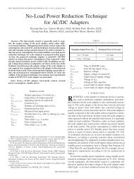
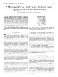
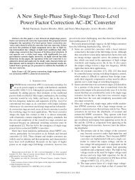
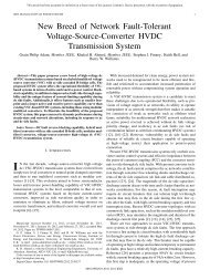
ABDEL-HAFEEZ AND GORDON-ROSS: DIGITAL <strong>CMOS</strong> PARALLEL COUNTER ARCHITECTURE 1025Fig. 1. Functional block diagram of our proposed 8-bit parallel counter withstate look-ahead logic and counting logic. The state look-ahead logic consistsof all logic encompassed by the dashed box and the counting logic consists ofall other logic (not encompassed by the dashed box).3) The counter output is in radix-2 representation so thecount value can be read on-the-fly with no additional logicdecoding.4) Unlike previous parallel counter designs that have countlatencies of two or three cycles, depending on the counterwidth, our parallel counter has no count latency, which enablesthe count value to be read on-the-fly.The remainder of this paper is organized as follows.Section II discusses our proposed parallel counter circuit basedon a <strong>CMOS</strong> implementation scheme. Section III providestiming analysis and related formulas. Section IV presentssimulation results for our counter synthesized to an Alterafield-programmable gate-array (FPGA) device as well as apost layout net-list using the HSPICE simulator. Finally, weconclude and provide future directions in Section V.II. PARRALLEL COUNTER ARCHITECTUREFig. 1 depicts our proposed parallel counter architecture fora sample 8-bit counter. The main structure consists of the statelook-ahead path (all logic encompassed by the dashed box)and the counting path (all logic not encompassed by the dashedbox). We construct our counter as a single mode counter, whichsequences through a fixed set of preassigned count states, ofwhich each next count state represents the next counter valuein sequence. The counter is partitioned into uniform 2-bitsynchronous up counting modules. Next state transitions incounting modules of higher significance are enabled on theclock cycle preceding the state transition using stimulus fromthe state look-ahead path. Therefore, all counting modulesconcurrently transition to their next states at the rising clockedge (CLKIN).In this section, we describe the architecture and functionalityof our parallel counter, the derivation of each counter state equation,and area analysis.A. Architectural FunctionalityThe counting path’s counting logic controls counting operationsand the state look-ahead path’s state look-ahead logicanticipates future states and thus prepares the counting pathfor these future states. Fig. 1 shows the three module typesFig. 2. Module-1 (a) hardware schematic and (b) state diagram. Note that the1inQEN 1 denotes that this is the QEN for module-1.(module-1, module-2, and module-3 , where ,etc. (increasing from left to right) and represents the positionof module-3) used to construct both paths. Module-1 andmodule-3 are exclusive to the counting path and each modulerepresents two counter bits. Module-2 is a conventional positiveedge triggered DFF and is present in both paths. In the countingpath, each module-3 is preceded by an associated module-2.Module-3 ’s serve two main purposes. Their first purposeis to generate all counter bits associated with their orderedposition and the second purpose is to enable (in conjunctionwith stimulus from the state look-ahead path) future states insubsequent module-3 ’s (higher values) in conjunction withstimulus from the state look-ahead path.1) Counting Path: Module-1 is a standard parallel synchronousbinary 2-bit counter, which is responsible forlow-order bit counting and generating future states for allmodule-3 ’s in the counting path by pipelining the enablefor these future states through the state look-ahead path. Fig. 2depicts the (a) hardware schematic and (b) state diagramfor module-1. Module-1 outputs (the counter’s twolow-order bits) and(the 1 indenotes that this is the for module-1). connectsto the module-2’s input.The placement of module-2s in the counting path is critical tothe novelty of our counter structure. Module-2s in the countingpath act as a pipeline between the module-1 and module-3 1and between subsequent module- s (see Fig. 1). Module-2placement (coupled with state look-ahead logic describedin Section II-A2) increases counter operating frequency byeliminating the lengthy AND-gate rippling and large AND gatefan-in and fan-out typically present in large width parallelcounters. Thus, instead of the modules of higher significancerequiring the ANDing of all enable signals from modules oflower significance, modules of higher significance (module-3s in our design) are simply enabled by the module-3 ’s precedingmodule-2 and state look-ahead logic. Since the couplingof module-2 with module-3 1 introduces an extra cycle delaybefore module-3 1 is enabled, module-2’s is triggeredwhen the module-1’s count(note that this is onlythe case for the left most module-2 in the counting path inFig. 1, as subsequent module-2s require state look-ahead logicas well). Thus, the module-2s in the counting path providea 1-cycle look-ahead mechanism for triggering the module-3
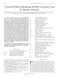
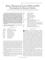
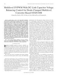
1026 IEEE TRANSACTIONS ON VERY LARGE SCALE INTEGRATION (VLSI) SYSTEMS, VOL. 19, NO. 6, JUNE 2011Fig. 3. Module-3S (a) hardware schematic and (b) state diagram. Note that the3inQEN 3 denotes that this is the QEN for module-3.Fig. 4. Generalized counter topology for an N -bit counter showing state lookaheadpath details.’s, enabling the module-2s to maintain a constant delay forall stages and all module-3 ’s to count in parallel at the risingclock edge instead of waiting for the overflow rippling in astandard ripple counter.Fig. 3 depicts the (a) hardware schematic and (b) state diagramfor module-3 . Module-3 is a parallel synchronous binary2-bit counter whose count is enabled by . connectsto the output of the preceding module-2. Module-3outputs (which connect to the appropriate count outputbits and as shown in Fig. 1) andC (the 3 in denotes that this isthe for module-3 ). The state look-ahead logic providesthe input (details discussed in Section II-A2). connectsto the subsequent module-2’s input and provides theone-cycle look ahead mechanism.2) State Look-Ahead Path: The state look-ahead path operatessimilarly to a carry look-ahead adder in that it decodesthe low-order count states and carries this decoding over severalclock cycles in order to trigger high-order count states. Thestate look-ahead logic is principally equivalent to the one-cyclelook-ahead mechanism in the counting path. For example, ina 4-bit counter constructed of two 2-bit counting modules, thecounting path’s module-2 decodes the low-order stateand carries this decoding across one clock cycle and enablesat module-3 1 (see Fig. 1) on the next rising clockedge. This operation is equivalent to decodingand enablingon the next immediate rising clockedge. The state look-ahead logic expands this principle to an-cycle look-ahead mechanism. For example, in a traditional6-bit ripple counter constructed of three 2-bit counting modules,the enabling of bits happens only after decoding theoverflow at to enable and decoding the overflowat to enable . However, combining the one cyclelook-ahead mechanism in the counting path forand a two-cycle look-ahead mechanism forfromcan enable ( is pipelined across two cyclesandis pipelined across one cycle, thus enablingat the next rising clock edge (further details will be discussedin Section II-C). Thus, enabling the next state’s high-order bits depends on early overflow pipelining across clock cyclesthrough the module-2s in the state look-ahead path. Thisstate look-ahead logic organization and operation avoids the useof an overhead delay detector circuit that decodes the low ordermodules to generate the enable signals for higher order modules,and enables all modules to be triggered concurrently on theclock edge, thus avoiding rippling and long frequency delay.Fig. 4 depicts a generalized -bit counter topology, revealingstate look-ahead path details. Module-2s in the statelook-ahead logic are responsible for propagating (pipelining)the early overflow detection to the appropriate module-3. Early overflow is initiated by the module-1 through theleft-most column of decoders (state-2, state-3, etc.). Theoutput of the right-most module-2 (, etc.) in eachearly overflow pipelining chain is connected to the inputof the appropriate module-3 . The module-3 ’s output(note and referto the two counting bits stored internally at each module-3and do not refer to and of the outputted count value),signaling that not only has that module-3 overflowed, but allmodules preceding that module-3 have also overflowed, thusenabling the count in the subsequent module-3 .Each module-2s early overflow pipelining chain is precededby a small logic block (State-X), which decodes the appropriatevalue for early overflow pipelining. denotesthe number of clock cycles that the early overflow pipeliningmust carry through. For example, State-3 means that the earlyoverflow signal must carry through two clock cycles, and thusenable the appropriate module-3 on the third clock cycle.Each State- block consists of simple two-input AND logic thatdecodes the module-1’s output. Fig. 1 shows the internallogic for State-2 and State-3 as and , respectively,and whose outputs and (see Fig. 1), respectively,are connected to the appropriate module-2s input, thusstarting the early overflow pipelining exactly clock cyclesbefore the overflow must be detected to enable counting in amodule-3 . Note that module-1 and module-3 may be ofarbitrary bit width, and thus the same look-ahead principlewould equally apply.
ABDEL-HAFEEZ AND GORDON-ROSS: DIGITAL <strong>CMOS</strong> PARALLEL COUNTER ARCHITECTURE 1027B. Derivation of <strong>Counter</strong> State EquationsIn this subsection, we present the derivation of each counterstate equation based on the early overflow pipelining equation(which preceding bit values are necessary to enable a subsequentcounter bit to change). As an example, we derive thecounter state equations for the sample 8-bit counter presentedin Fig. 1. We denote a past counter state using lower caseand the next counter state using upper case. Thus, the counter state equationnecessary to enable will contain Consequently,at module-3 1 is enabled by the past statefrom module-1, which carries through one clock cycle in thecounting path’s module-2, and enables module-3 1 on the nextrising clock edge (the one-cycle look-ahead mechanism definedin Section II-A1).The 4-bit counter state equation (counter state outputs ofmodule-1 and module-3 1 in Fig. 1) can be expressed asTABLE IRELEVANT INTERMEDIATE SIGNAL (SEE FIG. 1)VALUES FORCOUNTER STATES 0–15Pipelined (1)where Pipelined denotes that the past bit values representedby must be pipelined across one clock cycle. This notationmay be recursively applied such that Pipelined (Pipelined )would pipeline across two clock cycles, and so forth. Consequently,the 6-bit counter state equation (counter state outputsof module-1, module-3 1, and module-3 2 in Fig. 1) can be expressedasPipelinedPipelined (2)The complete 8-bit counter state equation (counter state outputsof module-1, module-3 1, module-3 2, and module-3 3 inFig. 1) can be expressed as:For (1), the past state is pipelined using the one-cyclelook-ahead mechanism provided by the left-most module-2 inthe counting path. For (2) and (3), the state look-ahead pathprovides the past states and through early overflowpipelining. Table I depicts all relevant intermediate signal valuesfor the four least significant bits of the 8-bit counter in Fig. 1.C. <strong>Counter</strong> Area AnalysisIn this subsection, we analyze the area overhead of ourparallel counter architecture based on the number of internalcomponents (which can easily be translated to gate counts).Module-1 is a 2-bit counter that provides a set of early overflowstates to enable future states. In general, if module-1 is an-bit counter, one early overflow state inputs into the countingpath and the remainder of the early overflow states input intothe state look-ahead path. Therefore, the total number of earlyoverflow states (EO) generated by module-1 is(3)(4)and the number of early overflow components (denoted asstate- in Fig. 4) required to propagate earlyoverflow states in the state look-ahead path isIn order to generalize a skeleton structure to apply to variablecounter widths, we consider the number of module-2s associatedwith each module-3 (one vertical column of module-2sfor every module-3 in Fig. 4). One module-2 is in the countingpath while the remainder of the module-2s are in the state lookaheadpath. The number of module-2s in the vertical columnstate look-ahead pathiswhere denotes module-3 ’s horizontal position.Thus, the total number of module-2s in each vertical column(including both the counting and state look-aheadpaths) isUsing (4), the maximum allowable counter size (CS) isUsing (8), the required number of module-3 ’s in thecounting path , which is equal to the number ofmodule-2s in the counting path is(5)(6)(7)(8)(9)
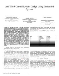
1028 IEEE TRANSACTIONS ON VERY LARGE SCALE INTEGRATION (VLSI) SYSTEMS, VOL. 19, NO. 6, JUNE 2011TABLE IINUMBER OF COMPONENTS AND TOTAL COUNTER RANGE FOR SAMPLECOUNTERS WITH RESPECT TO THE MODULE-1 SIZE IN BITSFurthermore, the total number of module-2s in the state lookaheadpathis(10)and, the total number of module-2s in the entire counter architectureis(11)The total number of AND logic in the state look-ahead path(AND SLP) is(12)Fig. 5. Timing diagram for the 8-bit counter in Fig. 1 starting with an initialcount value of 101000 and operating for seven subsequent count operations.Clock cycle counts are denoted along the top of the timing diagram.TABLE IIISYMBOL NOTATION DEFINITIONS FOR THE TIMING DIAGRAM IN FIG. 5Table II depicts component counts for various counter sizesbased on the module-1 size in number of bits .III. TIMING ANALYSISIn this section, we provide timing analysis for our parallelcounter. We present detailed operational timing for a samplecounting sequence, followed by clock period analysis.A. Timing DiagramFig. 5 depicts the timing diagram for the sample 8-bit counterin Fig. 1, showing all related events, which occur for a startcount state of 101000 (i.e.,and) and seven subsequent counts ending in a countstate of 101111 (i.e.,and). In this example, we begin the counter at a state suchthat subsequent count increments affect most of the modules inFig. 1, but yet the required explanation is manageable (note thatsince do not change in this example and modules associatedwith those bits will not change, these signals are not shownin the timing diagram). Table III summarizes symbol notationdefinitions. Without loss of generality we assume all moduleshave an equal access time , logic AND gates have a unit delayof , and all DFFs are positive-edge triggered. In each cycle,we do not mention every signal event, only those relevant to theprogression of the example.After CLKIN’s rising edge in clock cycle 1, the count stateupdates to 101001 after a delay of (module-1’s ).The change to triggers the two-input AND gates in the statelook-ahead path, and sets the early overflow detection signalsand after a delay of .After CLKIN’s rising edge in clock cycle 2, the count stateupdates to 101010 after a delay of (module-1’s). The change state triggers module-1’s internal twoinputAND gate (see Fig. 2) with a delay ofresulting in (where refersto the input of the module-2 to left of module-1). Concurrently,in the state look-ahead path, after a delay of thuspipelining the early overflow detection signal from inthe previous clock cycle, while after a delay ofdue to module-1’s state change. All subsequent module-3 ’soutputs remain constant.
ABDEL-HAFEEZ AND GORDON-ROSS: DIGITAL <strong>CMOS</strong> PARALLEL COUNTER ARCHITECTURE 1029After CLKIN’s rising edge in clock cycle 3, the count stateupdates to 101011 (module-1’s) and(due to pipelining the early overflow signal) after a delay of . Concurrently,triggers after a delay of and (due topipelining the early overflow signal ) after a delay of. All subsequent module-3 ’s outputs still remainconstant.Clock cycle four reveals the counter’s novel parallel updatingmechanism. After the rising clock edge in cycle four, the countstate updates tothrough simultaneousupdates of at module-1 and module-3 1 aftera delay of . These updates occur simultaneously (insteadof waiting for the overflow pipelining inherent in ripple-stylecounters) because in the previous clock cycle (due tothe one-cycle look-ahead mechanism). Concurrently,resets due to pipeliningin clock cycle three andholds because although . Meanwhile,the state look-ahead signaltriggers after adelay of , while all other signalshold. All subsequent module-3 ’soutputs still remain constant.After CLKIN’s rising edge in clock cycle five, the count stateupdates to after a delay of , thus triggeringand after a delay of . pipelinesthe early overflow detection signal after a delay of, thus triggering after a delay of since. still holds, but will trigger on the nextclock cycle (clock cycle six) because their input module-2s store1 during this clock cycle. Again, all subsequent module-3 ’soutputs still remain constant as well as module-3 1.After CLKIN’s rising edge in clock cycle six, the countstate updates to after a delay of andafter a delay of . Concurrently, the state look-aheadpath pipelines and after a delay of ,thus triggering after a delay of (consisting of theaccess time and the module-3’s internal AND gate delaysincewere already high in this cycle as well as theprevious cycle).Consequently, a similar sequence repeats through the remainingclock cycles, with the key feature being counter stateanticipation (parallel count operation) by pipelining early overflowdetection through state look-ahead logic and the countingpath, thus triggering all modules concurrently and avoiding ripplingand high fan-in logic gates for detecting the next counterstate. These mechanisms enable all modules to maintain thesame gate delay (unit delay) regardless of counter width.B. Clock Period AnalysisUsing the timing diagram depicted in Fig. 5, we first derivethe clock period for an 8-bit counter based on the signalpropagation through modules and AND gate logic, and subsequentlygeneralize the derivation for an -bit counter.must be greater than both the counting and the state look-aheadpath’s delay (see Table III for symbol notation definitions)(13)Fig. 6. Simulation waveforms for a synthesized HDL representation of our8-bit parallel counter operating on an Altera MAX300A device. The clock(SCLK) frequency is 250 MHz and V = 3.3 V.where (13) is the delay between a module-3 and a subsequentmodule-2. In addition, (13) can be represented as logic gate delaysin order to avoid technology dependent factors, such thatresulting in(14)(15)for the 8-bit counter in Fig. 1. Even though further speedenhancements are possible using various advanced designtechniques for the module-1 and module-3S [9], [20], [27],[40], the purpose of this paper is to emphasize the architectureand parallel operation rather than improving individual componentsusing high cost technology and special circuit designtechniques. These improvements are orthogonal to our work.In order to derive the clock period for larger counter widths,the access time in module-1 becomes the worst-case delaysince larger module-1s generate more early overflow states asdepicted in (4). Hence, for a 3-bit module-1 (17-bit maximumcounter width), the module-1 delay becomes approximatelyequal to the module-3 delay and, thus, implying no furtherdelay than (13). For a 4-bit module-1 (34-bit maximum counterwidth), module-1 becomes the critical path such that(16)since the remainder of the modules (module-2s and module-3s), as well as the three-input AND gates, do not change (demonstratedin Fig. 4). The key emphasis of (16) is that the delay isbounded by module-1 for counter widths greater than 17-bits. Ingeneral, for very large counter widths (module-1s greater than4-bits) further enhancements can be made using our topologyas a sub-topology of a complete structure. We can further generalizethe clock period of our proposed counter based on an-bit module-1 and counter width derived in (8)(17)
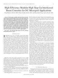
1030 IEEE TRANSACTIONS ON VERY LARGE SCALE INTEGRATION (VLSI) SYSTEMS, VOL. 19, NO. 6, JUNE 2011On the other hand, also has a secondary constraintdue to the clock path’s wire parasitic load since the clock drivesall modules in the structure simultaneously, which may be alleviatedby using clock distributing and buffering approaches [4],[5] with an efficient layout implementation.IV. EXPERIMENTAL RESULTSWe present synthesis and simulation results for the 8-bit parallelcounter in Fig. 1. We provide both functional verificationusing a synthesized HDL representation and performance verificationusing an HSPICE simulation of our parallel counter.A. Functional VerificationIn order to illustrate our counter’s parallel counting ability,Fig. 6 depicts the simulation waveforms for the top-level designoutputs (counter value) for severalcount iterations. We synthesized the HDL using Quartus-IIfor an Altera MAX3000A FPGA device [3] running at 250 MHz(as we are presenting functional verification only, no optimizationswere performed to increase operating frequency, and thus250 MHz does not reflect the maximum operating frequency).The vertical axis shows traced logic values, while the horizontaltime scale is represented in nanoseconds. All signal traces reflectthe block diagram in Fig. 1 and follow precise countertiming, for example, and. In addition, it should be noted that allchanges show similar timing delay with respect to CLKIN, exemplifyingthe key novel parallel counting feature of our design.As reported by the Altera Quartus power analysis tools [3],the parallel counter has an average power dissipation of 5.41mW. When synthesized using two-input NAND gates, the 8-bitparallel counter required a total of 235 gates, which consistedof 23 gates for the module-1, 9 gates for each module-2, and30 gates for each module-3 , as well as 8 output buffers and 2input buffers for the clock and reset signals.B. Performance VerificationTo layout our parallel counter, we used Berkley’s Magic circuitlayout tool [5]. We generated the HSPICE net-list from theMagic layout using resistance-capacitance parasitic extractionand performed performance verification using HSPICE 0.15-m TSMC n-well <strong>CMOS</strong> technology [34] operating at 1.35 Vand 125 C, which provides worst case corner delays [15], [29]).Fig. 7 depicts the HSPICE simulation waveform captured usingthe Mentor Graphics Powertrain waveform viewer [23]. TheHSPICE simulation achieved a maximum operating frequencyof 2 GHz for our 8-bit parallel counter with a safe slew raterise/fall margin of 0.2 ns/v.Fig. 8 depicts worst-case maximum clock frequency versescounter width in bits. Overall, the clock frequency decreases ata steady rate of for increased counter widths rangingfrom 8 to 16 bits and 17 to 34 bits. This decrease reflects theincreasing cost of parasitic components on the system clock(CLKIN) and not additional gate delays [(4) and (5) show thatas the counter width increases between these two ranges, thenumber of components does not increase]. Subsequently, operatingfrequency is secondarily affected by clock path parasiticload, and minimizing this load using a clock tree and preciseFig. 7. HSPICE waveforms for our 8-bit parallel counter (CLK = 2 GHz,V = 1.65 V) using TCMC 0.15-m technology. The horizontal scale is innanoseconds and the vertical scale is in volts.Fig. 8. Worst-case maximum clock frequency verses counter width (size) inbits.layout could increase operating frequency. On the other hand, alarger decrease in clock frequency occurs at counter widths of8, 17, and 35 bits, which correspond to the increase in module-1size to accommodate larger counter widths [(4) analyzes theincrease in early overflow states generated and (17) analyzesthe increased gate delay, which amounts to one early overflowstate and one extra gate delay per increase in module-1 size,respectively].Fig. 9 depicts worst-case total power consumption (static anddynamic) verses varying clock frequencies for our 8-bit parallelcounter. We measure power consumption by setting the powersupply voltage to 1.65 V at 0 C for worst-case process corner[3], [15], [29], [34]. At clock frequencies of 2 GHz, 1 GHz, and200 MHz, the parallel counter consumes 13.89, 5.78, and 1.872mW, respectively. Overall, power consumption increases at amoderate linear rate of 7.3 W/MHz with respect to increasingclock frequencies. The power consumption is primarily dominatedby the module’s dynamic switching activity and local interconnectson all modules (which is at most a three input logicfan-in and one output logic fan-out with the exception of thesystem clock). The transistor size is optimized for high performanceoperation and low power by limiting the transistor width
ABDEL-HAFEEZ AND GORDON-ROSS: DIGITAL <strong>CMOS</strong> PARALLEL COUNTER ARCHITECTURE 1031Fig. 9. <strong>Counter</strong> power consumption verses varying clock frequencies for our8-bit parallel counter.Fig. 10.Total <strong>CMOS</strong> transistor count verses counter bit size.TABLE IVTOTAL AND COMPONENT TRANSISTOR REQUIREMENTSFOR THE 8-BIT COUNTERto 5 m and the channel length to 0.15 m, with the exceptionof clock buffer transistors, which are approximately 15 minwidth and 0.15 m in length. Thus, minimizing the dynamicswitching activity and preserving the static leakage power to onthe order of nano-Watts.Table IV summarizes the total number of components andtransistors required per component for our 8-bit counter basedon the component design modules depicted in Figs. 2 and 3using <strong>CMOS</strong> transistor design structures. Module-1, module-2,and module-3 components require 70, 90, and 24 transistors, respectively.The complete 8-bit counter requires only 510 transistors,which equals approximately 78 125 m of silicon diearea.Fig. 10 depicts total transistor count verses counter widthin bits for particular counter ranges (trans count per ranges)and per 2-bit increments in counter width (trans count per2-bits). Transistor requirements increase by approximately3 for each counter range increase (a subsequent increase inmodule-1 width). For counters widths ranging from 1 to 8 bits,9 to 17 bits, 18 to 34 bits, and 35 to 67 bits, the parallel counterrequires 510, 1 555, 5 206, and 18 584 transistors, respectively.Analyzed as transistor increase per 2-bit increments in counterwidth reveals a modest linear increase of approximately 1.2per 2-bits.C. Comparison ResultsTable V compares our parallel counter to counter designs byAlioto et al. [2] (results reported as published), Kakarountaset al. [17] (results reported as published), and Yeh et al. [41](we designed and simulated Yeh’s design using 0.15 m to obtainthese results) in terms of power consumption in milliwatts,maximum clock frequency in gigahertz, and area requirementsin number of transistors for an 8-bit counter. In Alioto’s design,the number of cascading stages limits the maximum clockfrequency and the biasing current is a factor in the maximumpower consumption. These stages [2] were designed using a differentialpair of MOS current-mode logic with level shifters,where the propagated voltage swings between stages rangedfrom (Vdd-Vth)toVth. Alioto’s design is not amenable to VLSIimplementation and continued technology scaling since the operatingmargin is 1/3 . Additionally, even though Alioto’sdesign has low power consumption, the design requires a shutdownpower source due to the continuous standby current drawnat every stage’s biasing circuitry and level shifters, thus consuminglarge leakage power. Table V shows that even thoughAlioto’s design consumes less power and requires fewer transistorsthan our parallel counter, the maximum clock frequencyis only 500 MHz.Kakarountas et al. [17] proposed a parallel counter structuredivided into segments of 4-bit systolic counters consisting ofa cascaded series of T-type flip-flops (TFFs). The estimatedclock frequency was reported as, where , and are the delays of athree-input AND gate, a two input AND gate, and TFF accesstime, respectively. However, the setup-hold times and the XORgates for the TFFs should also be considered in the attainableclock frequency. Consequently, Kakarountas’s design reducedthe counter delay by using more DFFs inserted between systoliccounter segments at the cost of more cascaded logic to detectthe write sequence and reload values to the most-significantbits. These additions make Karakountas’s design unattractivefor wide-range counters due to increases in the chain of
1032 IEEE TRANSACTIONS ON VERY LARGE SCALE INTEGRATION (VLSI) SYSTEMS, VOL. 19, NO. 6, JUNE 2011TABLE VCOMPARISON OF OUR PROPOSED PARALLEL COUNTER WITH PREVIOUS WORK BY ALIOTO ET AL. [2], KAKAROUNTAS ET AL. [17], AND YEH ET AL. [41]cascaded detected logic gates. Kakarountas et al. [17] reportedcontroversial results when for counter widths of 32-bits andlarger. Furthermore, the counter output was not in radix-2 binaryformat, thus requiring further processing of the counter outputand increasing the counter delay.Yeh et al. [41] presented a parallel counter with a carry-selectstructure and a half-adder component associated with every DFFin order to generate the appropriate anticipated states by a factorof approximately 2. Yeh’s design structure was divided into irregularsections that required different partitions for differentcounter sizes and more bits were associated with partitions ofhigher significance. The maximum clock frequency was limitedby the half-adder delay, the chain of large fan-in AND gates, andthe time required to load the DFFs. The design used a long chainof AND gates in order to detect the anticipated states for the partitionsof lower significance, which made the design irregularand less attractive for wide-range counters. Consequently, thestructure was enhanced by inserting DFFs in the AND chain inorder to alleviate the long delay required for wide-range counters,with the side effect of the count being read after a two orthree cycle delay (depending on the counter length), instead ofa one cycle delay as in classical counter designs.V. CONCLUSIONIn this paper, we presented a scalable high-speed parallelcounter using digital <strong>CMOS</strong> gate logic components. Ourcounter design logic is comprised of only 2-bit counting modulesand three-input AND gates. The counter structure’s mainfeatures are a pipelined paradigm and state look-ahead pathlogic whose interoperation activates all modules concurrently atthe system’s clock edge, thus providing all counter state valuesat the exact same time without rippling affects. In addition, thisstructure avoids using a long chain detector circuit typicallyrequired for large counter widths. An initial -bit countingmodule pre-scales the counter size and this initial module isresponsible for generating all early overflow states for modulesof higher significance. In addition, this structure uses a regularVLSI topology, which is attractive for continued technologyscaling due to two repeated module types (module-2s andmodule-3s) forming a pattern paradigm and no increase infan-in or fan-out as the counter width increases, resulting in auniform frequency delay that is attractive for parallel designs.Consequently, the counter frequency is greatly improved byreducing the gate count on all timing paths to two gates usingadvanced circuit design techniques. However, extra precautionsmust be considered during synthesis or layout implementationsin order to aligned all modules in vertical columns with thesystem clock. This layout avoids setup and hold time violations,which might ultimately be limited by race conditions.Results reveal that our counter frequency drops at a rate of(where is the counter width in bits) due to parasiticcomponents that inhibit large fan-out of the system clockpath (since all modules operate simultaneously) and the delayof an initial module that increases in size as the counter widthincreases. This logarithmic frequency drop places our designamongst the fastest counter designs reported in literature, to thebest of our knowledge. Furthermore, area requirements increaseat a modest rate of 1.2 transistors per 2-bit increase in counterwidth. Similarly, power consumption increases at a moderatelinear rate of 7.3 W/MHz with respect to each doubling of theclock frequency. Finally, the counter output is determined directlyon-the-fly with no additional decoding latency necessaryto decode the final output pattern as with most counter designs.REFERENCES[1] S. Abdel-Hafeez, S. Harb, and W. Eisenstadt, “High speed digital<strong>CMOS</strong> divide-by-N frequency divider,” in Proc. IEEE Int. Symp.Circuits Syst. (ISCAS), 2008, pp. 592–595.[2] M. Alioto, R. Mita, and G. Palumbo, “Design of high-speed power-efficientMOS current-mode logic frequency dividers,” IEEE Trans. CircuitsSyst. II, Expr. Briefs, vol. 53, no. 11, pp. 1165–1169, Nov. 2006.[3] Altera Corp., Santa Clara, CA, “FLEX8000, field programmable gatearray logic device,” 2008.[4] A. Bellaour and M. I. Elmasry, Low-Power <strong>Digital</strong> VLSI Design Circuitsand Systems. Norwell, MA: Kluwer, 1995.[5] J. Ousterhout, Berkeley, 1980, “Berkley magic layout tools,” 1980.[Online]. Available: http://opencircuitdesign.com/magic/[6] B. Chang, J. Park, and W. Kim, “A 1.2 GHz <strong>CMOS</strong> dual-modulusprescalar using new dynamic D-type flip-flops,” IEEE J. Solid-StateCircuits, vol. 31, no. 5, pp. 749–752, May 1996.[7] M. Ercegovac and T. Lang, “Binary counters with counting period ofone half adder independent of <strong>Counter</strong> size,” IEEE Trans. Circuits Syst.,vol. 36, no. 6, pp. 924–926, Jun. 1989.[8] M. D. Ercegovac and T. Lang, <strong>Digital</strong> Arithmetic. San Mateo, CA:Mogan Kaufmann, 2004.[9] A. Fard and D. Aberg, “A novel 18 GHZ 1.3 mW <strong>CMOS</strong> frequency dividerwith high input sensitivity,” in Proc. Int. Symp. Signals, Circuits,Syst., Jul. 2005, pp. 409–412.[10] C. Foster and F. Stockton, “Counting responders in an associativememory,” IEEE Trans. Comput., vol. 20, no. 12, pp. 1580–1583, Dec.1971.[11] D. C. Hendry, “Sequential lookahead method for digital counters,”IEEE Electron. Lett., vol. 32, no. 3, pp. 160–161, Feb. 1996.
ABDEL-HAFEEZ AND GORDON-ROSS: DIGITAL <strong>CMOS</strong> PARALLEL COUNTER ARCHITECTURE 1033[12] N. Homma, J. Sakiyama, T. Wakamatsu, T. Aoki, and T. Higuchi,“A systematic approach for analyzing fast addition algorithms usingcounter tree diagrams,” in Proc. IEEE Int. Symp. Circuits Syst. (ISCAS),2004, pp. V-197–V-200.[13] B. Hoppe, C. Kroh, H. Meuth, and M. Stohr, “A 440 MHz 16 bit counterin <strong>CMOS</strong> standard cells,” in Proc. IEEE Int. ASIC Conf., Sep. 1998,vol. 244, pp. 241–244.[14] Y. Ito, K. Nakano, and Y. Yamagishi, “Efficient hardware algorithmsfor n choose K counters,” in Proc. 20th Int. <strong>Parallel</strong> Distrib. Process.Symp., Apr. 2006, pp. 1–8.[15] Y. I. Ismail and E. G. Friedman, On-Chip Inductance in High SpeedIntegrated Circuits. Norwell, MA: Kluwer, 2001.[16] R. F. Jones, Jr. and E. E. Swartzlander, Jr., “<strong>Parallel</strong> counter implementation,”in Proc. 10th Symp. Comput. Arith., 1992, pp. 382–385.[17] A. P. Kakarountas, G. Theodoridis, K. S. Papadomanolakis, and C. E.Goutis, “A novel high-speed counter with counting rate independent ofthe counter’s length,” in Proc. IEEE Int. Conf. Electron., Circuits Syst.(ICECS), UAE, Dec. 2003, pp. 1164–1167.[18] R. H. Katz, Contemporary Logic Design. Redwood City, CA: Benjamin/Cummings,1994.[19] Y. Leblebici, H. Ozdemir, A. Kepkep, and U. Cilingiroglu, “A compacthigh-speed (31, 5) parallel counter circuit based on capacitivethreshold-logic gates,” IEEE J. Solid-State Circuits, vol. 31, no. 8, pp.1177–1183, Aug. 1996.[20] B. Liang, D. Chen, B. Wang, D. Cheng, and T. Kwasniewski, “A43-Ghz static frequency divider in 0.13 M standard <strong>CMOS</strong>,” in Proc.IEEE Canadian Conf. Elect. Comput. Eng. (CCECE), May 2008, pp.111–114.[21] P. Lin, K. E. Kerr, and A. S. Botha, “A novel approach for <strong>CMOS</strong>parallel counter design,” in Proc. 25th EUROMICRO Conf., 1999, pp.112–119.[22] D. R. Lutz and D. N. Jayasimha, “Programmable modulo-K counters,”IEEE Trans. Circuits Syst. I, Fundam. Theory Appl., vol. 43, no. 11, pp.939–941, Nov. 1996.[23] Mentor Graphics, Wilsonville, OR, “Mentor graphics powertrain,”1981. [Online]. Available: http://www.mentor.com/[24] N. Nikityuk, “Use of parallel counters for triggering nuclear instrumentsand methods in physics research,” , vol. A321, no. 3, pp.571–582, Oct. 1992.[25] B. Parhami, Computer Arithmetic: Algorithms and Hardware Designs.London, U.K.: Oxford Univ. Press, 2000.[26] K. Z. Pekmestzi and N. Thanasouras, “Systolic frequency-dividerscounters,” IEEE Trans. Circuits Syst. II, Analog Digit. Signal Process.,vol. 41, no. 11, pp. 775–776, Nov. 1994.[27] B. Razavi, RF Microelectronics. Upper Saddle River, NJ: Prentice-Hall, 1998.[28] J. Sakiyama, T. Aoki, and T. Higuchi, “<strong>Counter</strong> tree diagrams for designand analysis of fast addition algorithms,” in Proc. 33rd Int. Symp.Multiple Valued Logic (ISMVL), May 2003, pp. 1–8.[29] E. Sanchez-Sinencio and A. G. Andreou, Low-Voltage/Low Power IntegratedCircuits and Systems. New York: Wiley-IEEE press, 1998.[30] M. R. Stan, “Synchronous up/down counter with period independentof counter size,” in Proc. IEEE Symp. Comput. Arith., Asilomar, CA,Jul. 1997, pp. 274–281.[31] M. R. Stan, “Systolic counters with unique zero state,” in Proc. IEEEProc. Int. Symp. Circuits Syst. (ISCAS), 2004, pp. II-909–II-912.[32] M. R. Stan, A. F. Tenca, and M. D. Ercegovac, “Long and fast up/downcounters,” IEEE Trans. Comput., vol. 47, no. 7, pp. 722–735, Jul. 1998.[33] J. E. Swartzlander, “A review of large parallel counter designs,” inProc. IEEE Comput. Soc. <strong>Ann</strong>. Symp. VLSI Emerg. Trends VLSI Syst.Des. (ISVLSI), 2004, pp. 89–98.[34] Taiwan Semiconductor Manufacturer Corp., Taiwan, “0.15 m<strong>CMOS</strong>ASIC process digests,” 2002.[35] J. E. Vuillemin, “Constant time arbitrary length synchronous binarycounters,” in Proc. IEEE 10th Symp. Comput. Arith., 1991, pp.180–183.[36] D. Wong, G. DeMicheli, M. Flynn, and R. Huston, “A bipolar populationcounter using wave piplelining to achieve 2.5x normal clockfrequency,” IEEE J. Solid-State Circuits, vol. 27, no. 5, pp. 745–753,May 1992.[37] Xilinx, Inc., San Jose, CA, “Xilinx; The programmable logic databook,” Aug. 1997.[38] H. Yan, M. Biyani, and Kenneth, “A high-speed <strong>CMOS</strong> dual-phasedynamic-pseudo NMOS ((DP) ) latch and its application in a dualmodulusprescaler,” IEEE J. Solid-State Circuits, vol. 34, no. 10, pp.1400–1404, Oct. 1999.[39] C.-Y. Yang, G.-K. Dehng, J.-M. Hsu, and S.-I. Liu, “New dynamicflip-flops for high-speed dual-modulus prescaler,” IEEE J. Solid-StateCircuits, vol. 33, no. 10, pp. 1568–1571, Oct. 1998.[40] K. Yamamoto and M. Fujishima, “4.3 GHz 44 uW <strong>CMOS</strong> frequencydivider,” in Proc. IEEE Int. Solid-State Circuits Conf., 2004, pp.104–105.[41] C. Yeh, B. Parhami, and Y. Wang, “Designs of counters with nearminimal counting/sampling period and hardware complexity,” in Proc.Asilomar Conf. Signals, Syst., Comput., 2000, pp. 894–898.[42] D. Zhang, G. Jullien, W. Miller, and E. Swartzlander, “Arithmetic fordigital neural networks,” in Proc. IEEE 10th Symp. Comput. Arith., Jun.1991, pp. 58–63.Saleh Abdel-Hafeez (M’02) received the Ph.D. degreein computer engineering from the University ofTexas at El Paso, El Paso, and the M.S. degree fromNew Mexico State University, University Park.He was a former Senior Member of technicalstaff at S3.inc and Viatechnologies.com in the areaof mixed signal IC’s design. He also was adjunctProfessor with the Computer Engineering Department,Santa Clara University, Santa Clara, CA,from 1998 to 2002. He is currently the Chairmanof the Computer Engineering Department, JordanUniversity of Science and Technology, Irbid, Jordan. He has two distinguishedUSA patents 6 265 509 and 6 356 509 with S3.inc. His current research interestincludes the area of high speed IC’s computer arithmetic algorithms and mixedsignal design.<strong>Ann</strong> <strong>Gordon</strong>-<strong>Ross</strong> (M’00) received the B.S. andPh.D. degrees in computer science and engineeringfrom the University of California, Riverside, in 2000and 2007, respectively.She is currently an Assistant Professor withthe Department of Electrical and Computer Engineering,University of Florida, Gainesville. Sheis also a member of the NSF Center for HighPerformance Reconfigurable Computing (CHREC)at the University of Florida. Her research interestsinclude embedded systems, computer architecture,low-power design, reconfigurable computing, dynamic optimizations, hardwaredesign, real-time systems, and multi-core platforms.