Test Results: Ford PCM Downloads Compared to Instrumented
Test Results: Ford PCM Downloads Compared to Instrumented
Test Results: Ford PCM Downloads Compared to Instrumented
- No tags were found...

Create successful ePaper yourself
Turn your PDF publications into a flip-book with our unique Google optimized e-Paper software.
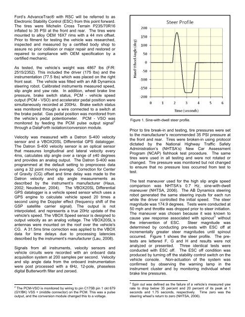
<strong>Ford</strong>’s AdvanceTrac® with RSC will be referred <strong>to</strong> asElectronic Stability Control (ESC) from this point forward.The tires were Michelin Cross Terrain P235/70R16inflated <strong>to</strong> 35 PSI at the front and rear. The tires weremounted <strong>to</strong> alloy OEM 16X7 rims with a 44 mm offset.Prior <strong>to</strong> fitment for testing the vehicle was researched,inspected and measured by a certified body shop <strong>to</strong>assure no prior collision or major repair and res<strong>to</strong>red orrepaired <strong>to</strong> compliance with OEM specification by acertified mechanic.As tested, the vehicle’s weight was 4867 lbs (F/R:2515/2352). This included the driver (175 lbs) and theinstrumentation (77.5 lbs) which was placed on the rightfront seat. The vehicle was fitted with an AB Dynamicssteering robot. Calibrated instruments measured speed,slip angle and yaw rate. In addition, wheel brake linepressure, brake switch status, <strong>PCM</strong> - vehicle speedoutput (<strong>PCM</strong> - VSO) and accelera<strong>to</strong>r pedal position weresimultaneously recorded at 200Hz. Brake switch statuswas moni<strong>to</strong>red through a wire connected <strong>to</strong> a switch atthe brake pedal. Gas pedal position was moni<strong>to</strong>red fromthe vehicle’s pedal potentiometer. <strong>PCM</strong> - VSO wasmoni<strong>to</strong>red by feeding the <strong>PCM</strong> pulse output signal 2through a DataForth isolation/conversion module.Velocity was measured with a Datron S-400 velocitysensor and a VBOX20SL Differential GPS datalogger.The Datron S-400 velocity sensor is an optical sensorthat measures longitudinal and lateral velocity every4ms, calculates slip angle over a range of ±40 degreesand provides an analog output. The Datron S-400 wasprogrammed at the default setting <strong>to</strong> preprocess datausing a 32 point moving average. Correction for Centerof Gravity (CG) offset and time delay was made <strong>to</strong> theDatron velocity and slip angle measurements asdescribed by the instrument’s manufacturer (Haus,2002; Neudecker, 2004). The VBOX20SL DifferentialGPS datalogger is a vehicle speed sensor which uses aGPS engine <strong>to</strong> calculate vehicle speed 20 times asecond using the Doppler effect (frequency shift of theGSP satellite carrier signal). The output is notinterpolated, and represents a true 20Hz update of thevehicle's speed. The VBOX Speed sensor is designed <strong>to</strong>output velocity as an analog voltage. The VBOX20SL’santennas were mounted on the roof over the vehicle'sCG. A 31.5ms time correction was applied <strong>to</strong> the VBOXdata for time delays due <strong>to</strong> processing latenciesdescribed by the instrument’s manufacturer (Lau, 2008).Signals from all instruments, velocity sensors andvehicle circuits were recorded with an onboard dataacquisition system at 200 samples per second. Velocityand slip angle data from the onboard instrumentationwere post processed with a 6Hz, 12-pole, phaselessdigital Butterworth filter and zeroed.Figure 1. Sine-with-dwell steer profile.Prior <strong>to</strong> tire break-in and testing, tire pressures were set<strong>to</strong> the manufacturer’s recommended 35 PSI pressure atthe front and rear. Tires were broken-in using pro<strong>to</strong>coldictated by the National Highway Traffic SafetyAdministration’s (NHTSA’s) New Car AssessmentProgram (NCAP) fishhook test procedure. The sametires were used in all testing and were not rotated orchanged. Tire pressure was moni<strong>to</strong>red but not changed<strong>to</strong> ensure that no pressure loss occurred from test <strong>to</strong>test.The test maneuver used for the high slip angle speedcomparison was NHTSA’s 0.7 Hz, sine-with-dwellmaneuver (NHTSA, 2006). The AB Dynamics steeringrobot generated the same steering inputs for each runwhile the driver controlled the initial speed. The steermagnitude was 174.9 degrees. <strong>Test</strong>s were conducted at50 mph and throttle was dropped prior <strong>to</strong> steer initiation.The maneuver was chosen because it was known <strong>to</strong>cause yaw response associated with spinout 3 withoutthe intervention of ESC. Steer magnitude wasdetermined by conducting pre-tests with ESC off atincrementally greater steer magnitudes until spinou<strong>to</strong>ccurred. Figure 1 shows the steer profile. The pretestsare lettered F, G and H and results were notanalyzed or presented. Three identical tests wereconducted with ESC off. The ESC off condition wasproduced by turning off the stability control switch on thevehicle console. Non-actuation of the system wasconfirmed by observing the warning lamp in theinstrument cluster and by moni<strong>to</strong>ring individual wheelbrake line pressures.2 The <strong>PCM</strong>-VSO is moni<strong>to</strong>red by wiring <strong>to</strong> pin C175B pin 1 ckt 679(GY/BK) VSS + (middle connec<strong>to</strong>r) on the <strong>PCM</strong>. This was a pulseoutput, and the conversion module changed this <strong>to</strong> a voltage.3 Spin out was defined as the failure of a vehicle’s measured yawrate <strong>to</strong> drop below 35 percent and 20 percent of its peak at 1seconds and 1.75 seconds, respectively. Time zero was thesteering wheel’s return <strong>to</strong> zero (NHTSA, 2006).