Test Results: Ford PCM Downloads Compared to Instrumented
Test Results: Ford PCM Downloads Compared to Instrumented
Test Results: Ford PCM Downloads Compared to Instrumented
- No tags were found...

You also want an ePaper? Increase the reach of your titles
YUMPU automatically turns print PDFs into web optimized ePapers that Google loves.
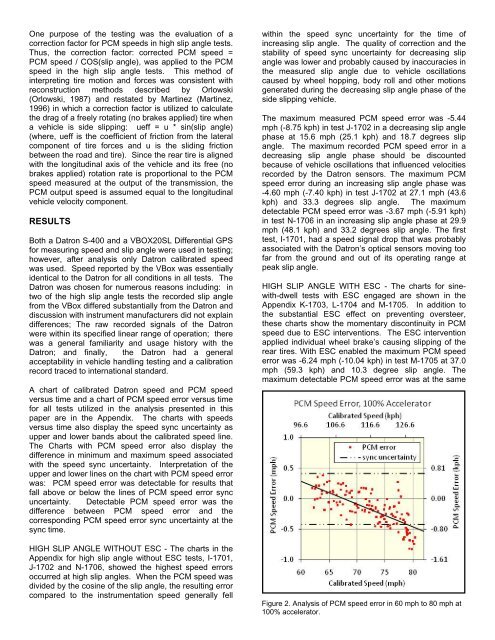
One purpose of the testing was the evaluation of acorrection fac<strong>to</strong>r for <strong>PCM</strong> speeds in high slip angle tests.Thus, the correction fac<strong>to</strong>r: corrected <strong>PCM</strong> speed =<strong>PCM</strong> speed / COS(slip angle), was applied <strong>to</strong> the <strong>PCM</strong>speed in the high slip angle tests. This method ofinterpreting tire motion and forces was consistent withreconstruction methods described by Orlowski(Orlowski, 1987) and restated by Martinez (Martinez,1996) in which a correction fac<strong>to</strong>r is utilized <strong>to</strong> calculatethe drag of a freely rotating (no brakes applied) tire whena vehicle is side slipping: ueff = u * sin(slip angle)(where, ueff is the coefficient of friction from the lateralcomponent of tire forces and u is the sliding frictionbetween the road and tire). Since the rear tire is alignedwith the longitudinal axis of the vehicle and its free (nobrakes applied) rotation rate is proportional <strong>to</strong> the <strong>PCM</strong>speed measured at the output of the transmission, the<strong>PCM</strong> output speed is assumed equal <strong>to</strong> the longitudinalvehicle velocity component.RESULTSBoth a Datron S-400 and a VBOX20SL Differential GPSfor measuring speed and slip angle were used in testing;however, after analysis only Datron calibrated speedwas used. Speed reported by the VBox was essentiallyidentical <strong>to</strong> the Datron for all conditions in all tests. TheDatron was chosen for numerous reasons including: intwo of the high slip angle tests the recorded slip anglefrom the VBox differed substantially from the Datron anddiscussion with instrument manufacturers did not explaindifferences; The raw recorded signals of the Datronwere within its specified linear range of operation; therewas a general familiarity and usage his<strong>to</strong>ry with theDatron; and finally, the Datron had a generalacceptability in vehicle handling testing and a calibrationrecord traced <strong>to</strong> international standard.A chart of calibrated Datron speed and <strong>PCM</strong> speedversus time and a chart of <strong>PCM</strong> speed error versus timefor all tests utilized in the analysis presented in thispaper are in the Appendix. The charts with speedsversus time also display the speed sync uncertainty asupper and lower bands about the calibrated speed line.The Charts with <strong>PCM</strong> speed error also display thedifference in minimum and maximum speed associatedwith the speed sync uncertainty. Interpretation of theupper and lower lines on the chart with <strong>PCM</strong> speed errorwas: <strong>PCM</strong> speed error was detectable for results thatfall above or below the lines of <strong>PCM</strong> speed error syncuncertainty. Detectable <strong>PCM</strong> speed error was thedifference between <strong>PCM</strong> speed error and thecorresponding <strong>PCM</strong> speed error sync uncertainty at thesync time.HIGH SLIP ANGLE WITHOUT ESC - The charts in theAppendix for high slip angle without ESC tests, I-1701,J-1702 and N-1706, showed the highest speed errorsoccurred at high slip angles. When the <strong>PCM</strong> speed wasdivided by the cosine of the slip angle, the resulting errorcompared <strong>to</strong> the instrumentation speed generally fellwithin the speed sync uncertainty for the time ofincreasing slip angle. The quality of correction and thestability of speed sync uncertainty for decreasing slipangle was lower and probably caused by inaccuracies inthe measured slip angle due <strong>to</strong> vehicle oscillationscaused by wheel hopping, body roll and other motionsgenerated during the decreasing slip angle phase of theside slipping vehicle.The maximum measured <strong>PCM</strong> speed error was -5.44mph (-8.75 kph) in test J-1702 in a decreasing slip anglephase at 15.6 mph (25.1 kph) and 18.7 degrees slipangle. The maximum recorded <strong>PCM</strong> speed error in adecreasing slip angle phase should be discountedbecause of vehicle oscillations that influenced velocitiesrecorded by the Datron sensors. The maximum <strong>PCM</strong>speed error during an increasing slip angle phase was-4.60 mph (-7.40 kph) in test J-1702 at 27.1 mph (43.6kph) and 33.3 degrees slip angle. The maximumdetectable <strong>PCM</strong> speed error was -3.67 mph (-5.91 kph)in test N-1706 in an increasing slip angle phase at 29.9mph (48.1 kph) and 33.2 degrees slip angle. The firsttest, I-1701, had a speed signal drop that was probablyassociated with the Datron’s optical sensors moving <strong>to</strong>ofar from the ground and out of its operating range atpeak slip angle.HIGH SLIP ANGLE WITH ESC - The charts for sinewith-dwelltests with ESC engaged are shown in theAppendix K-1703, L-1704 and M-1705. In addition <strong>to</strong>the substantial ESC effect on preventing oversteer,these charts show the momentary discontinuity in <strong>PCM</strong>speed due <strong>to</strong> ESC interventions. The ESC interventionapplied individual wheel brake’s causing slipping of therear tires. With ESC enabled the maximum <strong>PCM</strong> speederror was -6.24 mph (-10.04 kph) in test M-1705 at 37.0mph (59.3 kph) and 10.3 degree slip angle. Themaximum detectable <strong>PCM</strong> speed error was at the sameFigure 2. Analysis of <strong>PCM</strong> speed error in 60 mph <strong>to</strong> 80 mph at100% accelera<strong>to</strong>r.