EasyRadio Transceiver Module Datasheet - AVRcard
EasyRadio Transceiver Module Datasheet - AVRcard
EasyRadio Transceiver Module Datasheet - AVRcard
- No tags were found...

You also want an ePaper? Increase the reach of your titles
YUMPU automatically turns print PDFs into web optimized ePapers that Google loves.
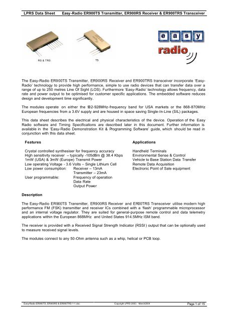
LPRS Data SheetEasy -Radio ER900TS Transmitter, ER900RS Receiver & ER900TRS <strong>Transceiver</strong>RS & TRSTSThe Easy-Radio ER900TS Transmitter, ER900RS Receiver and ER900TRS transceiver incorporate ‘Easy-Radio’ technology to provide high performance, simple to use radio devices that can transfer data over arange of up to 250 metres Line Of Sight (LOS). Furthermore ‘Easy-Radio’ technology allows frequency, datarate and power output to be optimised for customer specific applications. The embedded software reducesdesign and development time significantly.The modules operate on either the 902-928MHz-frequency band for USA markets or the 868-870MHzEuropean frequencies from a 3.6V supply and are housed in space saving Single-In-Line (SIL) packages.This data sheet describes the electrical and physical characteristics of the device. Operation of the <strong>EasyRadio</strong> software and Timing Specifications are described later in this document. Further information isavailable in the ‘Easy-Radio Demonstration Kit & Programming Software’ guide, which should be read inconjunction with this data sheet.FeaturesApplicationsCrystal controlled synthesiser for frequency accuracy Handheld TerminalsHigh sensitivity receiver – typically -105dBm @ 38.4 Kbps Environmental Sense & Control1mW (USA) & 3mW (Europe) Transmit PowerVehicle to Base Station Data TransferLow operating Voltage - 3.6 Volts – Single Lithium Cell Remote Data AcquisitionLow power consumption: Receiver – 13mA Electronic Point of Sale equipmentTransmitter – 23mAUser programmable: Frequency of operationData RateOutput PowerDescriptionThe Easy-Radio ER900TS Transmitter, ER900RS Receiver and ER00TRS <strong>Transceiver</strong> utilise modern highperformance FM (FSK) transmitter and receiver ICs combined with a ‘flash’ programmable microprocessorand an internal voltage regulator. They are suited for general-purpose remote control and data telemetryapplications within the European 868MHz and United States 914.5MHz ISM band.The receiver is provided with a Received Signal Strength Indicator (RSSI ) output that can be optionally usedto measure received signal levels.The modules connect to any 50-Ohm antenna such as a whip, helical or PCB loop.Easy-Radio ER900TS, ER900RS & ER900TRS 1-1.doc Copyright LPRS 2003. March2004 Page 1 of 15
LPRS Data SheetEasy -Radio ER900TS Transmitter, ER900RS Receiver & ER900TRS <strong>Transceiver</strong>ER900TS TransmitterAntenna (2)RegulatorVcc (3)RF TransmitterMicroProcessorTXD (5)RF Gnd (1)Gnd (4)Figure 1 Block Diagram31.0mm4 mm12 mmTop View(Transmitter)20.32mm1 23 4 5Pin Pitch 2.54 mm PCB Hole Size 1.0 mmPin DescriptionFigure 2 Physical DimensionsPinNoName Description Notes1 RF Gnd RF ground. Connect to antenna ground (coaxial cable screenbraid) and local ground plane. Internally connected to Pin 42 RF Out 50 Ohm RF output. Connect to suitable antenna See Note3 Vcc Positive supply pin. +3.6 to +6.0 Volts. This should be a‘clean’ noise free supply with less than 25mV of ripple4 Gnd Supply 0 Volt and Ground Plane5 TXD Transmit Data Digital Input 2Notes1. The module operates internally from an on board 3.3 Volt low drop regulator.2. TXD input will be correctly driven by logic operating at 5 Volts (CMOS & TTL logic levels). Inputshould not be driven by an analogue output.Easy-Radio ER900TS, ER900RS & ER900TRS 1-1.doc Copyright LPRS 2003. March2004 Page 2 of 15
LPRS Data SheetEasy -Radio ER900TS Transmitter, ER900RS Receiver & ER900TRS <strong>Transceiver</strong>ER900RS ReceiverThe Easy-Radio 900 Receiver is a complete sub-system that combines a high performance low power RFreceiver, a ‘flash’ programmable microcontroller and a voltage regulator (Figure 3). The microcontrollerprogrammes the functions of the RF receiver and provides the interface to the host system via a data output.It also contains programmable EEPROM memory that holds configuration data for the various receiveroperating modes. The microcontroller also relieves the host from the intensive demands of searching forsignals within the noise, recovering the received data and then presenting it to the host. A Received SignalStrength Indicator output can be optionally used to measure received signal levels. The module connects toa 50 Ohm antenna such as a whip, helical or PCB loop.Antenna (1)RegulatorRSSI Output (3)Vcc (8)RF ReceiverMicroProcessorBSY (4)Serial Data Output (5)Serial Data Input (6)RDY (7)Ground (9)RF Ground (2)Figure 3 Easy-Radio Receiver Block DiagramThe ER900RS will receive and decode any Easy-Radio transmission within range and on the samefrequency and deliver clean data to the host system for further processing.The Serial Data Output operates at programmable standard Baud Rates (default/typical 19,200Baud).Key parameters (frequency, power output, serial baud rate etc.) of the module may be programmed usingthe Easy-Radio PC Software. (See page 12 for Easy Radio Configuration Command Set.)Pin Out38.0 mm4.0mm14.0mmTop View(Receiver)10.0mm15.0 mm1 23 4 5 6 7 8 9Pin Pitch 2.54 mm PCB Hole Size 1.0 mmFigure 4 Physical DimensionsEasy-Radio ER900TS, ER900RS & ER900TRS 1-1.doc Copyright LPRS 2003. March2004 Page 3 of 15
LPRS Data SheetEasy -Radio ER900TS Transmitter, ER900RS Receiver & ER900TRS <strong>Transceiver</strong>Pin DescriptionPinNoName Description Notes1 Antenna 50 Ohm RF input/output. Connect to suitable antenna. See Note2 RF Ground RF ground. Connect to antenna ground (coaxial cable screenbraid) and local ground plane. Internally connected to otherGround pins.3 RSSI Received Signal Strength Indication - Analogue See Not e4 BSY Output (Low - Ready for data from Host) (High - Not Ready) CTS function5 Data Out Received Data Output SDO6 Data In ER command Input SDI7 RDY Input (Low – Host Ready to receive data) (High – Not Ready) RTS function8 Vcc Positive supply pin. +3.6 to +5.5 Volts. This should be a‘clean’ noise free supply with less than 25mV of ripple.9 Ground Connect to supply 0 Volt and ground planeChecklist1. The module operates internally from an on board 3.3 Volt low drop regulator. The logic levels of theinput/output pins are therefore between 0 Volt and 3.3 Volts. (See RS Performance Data).2. All digital inputs and outputs are intended for connection to low voltage logic devices. Do not connectany of the inputs or outputs directly to an RS232 port. The receiver module may be permanentlydamaged by the voltages (+/- 12V) present on RS232 signal lines. See Application Circuit (Figure11) for typical connection to an RS232 port via MAX232 interface IC.3. Outputs will drive logic operating at 5 Volts.4. If in handshaking mode, pin (7) of the ER900RS module should be connected directly to GND fordata to be delivered.Application & Operation ER900TS & RSFigure 5 shows a typical system block diagram comprising hosts (user’s application) connected to Easy-Radio Transmitters and Receivers. Host (A) will be monitoring (collecting data) and Host (B) will be receivingand processing this data.Transmit Data (TXD)RF LinkReceive Data OutputHost(A)Easy-RadioTransmitterEasy-RadioReceiverHost(B)Figure 5 Typical System Block DiagramThe Host (A) should provide the serial data input (up to a maximum 128 characters per packet) to the Easy-Radio transmitter. The data should be sent in ‘bursts’ therefore allowing adequate time for transmission andreception over the RF link (See Figure 6). The receiver, upon reception and decoding of the RF transmissionimmediately sends serial data to the Host B.Easy-Radio ER900TS, ER900RS & ER900TRS 1-1.doc Copyright LPRS 2003. March2004 Page 4 of 15
LPRS Data SheetEasy -Radio ER900TS Transmitter, ER900RS Receiver & ER900TRS <strong>Transceiver</strong>Data is sent and received in standard ‘RS232’ serial format (logic level only) and there is no restriction on thecharacters that may be sent.A. Host (A) sends serial data to the Easy-Radio Transmitter (A). The data must be continuouslystreamed at the selected baud rate and it fills an internal transmit buffer until either 128 bytes havebeen received or a gap of two bytes is detected.B. After detecting either the ‘End of Data’ gap or the ‘Buffer Full’ condition the controller enables RFtransmit and sends a fixed 10mS preamble followed by the data in the buffer which is Manchesterencoded at 19,200 Baud for efficient transmission across the RF link. Any Easy-Radio receiverswithin range that ‘hear’ the transmission will simultaneously lock onto the preamble, decode the dataand place it into their receive buffers.C. After checking the data for integrity the Data within the receive buffer of Easy-Radio Receiver (B) isthen sent continuously to the host at the selected baud rate.There is no ‘handshaking’ provided at either the transmitter or receiver. The user should therefore ensurethat sufficient time is allowed for the completion of transmission and reception of data. The TimingSpecifications detail these requirements (see page 8). Transmitter Host (A) must allow time for the ‘Over Air’transmission and for the receiving Host (B) to unload (and process) the data before sending any more newdata. The receiver Host (B) must always be ‘ready and waiting’ for data to arrive. It should be possible to usefast response ‘interrupts’ without any loss of data.With such a ‘one-way’ (simplex) system there is no confirmation of the satisfactory reception of the data andfor added reliability it is recommended that the data be sent, perhaps, repetitively several times. Forincreased reliability the use of transceivers (which can acknowledge packet reception) is recommended.Easy-Radio services do not provide automatic acknowledgement (or re-tries) but these can be provided bythe users application.AHost (A) sends serial data to Easy-Radio (A)Two Byte Delay for 'End of Data'BEasy-Radio (A) Transmits Over AirEasy-Radio (B) Receives & DecodesCEasy-Radio (B) sends serial data to Host (B)Figure 6 Serial DataEasy-Radio ER900TS, ER900RS & ER900TRS 1-1.doc Copyright LPRS 2003. March2004 Page 5 of 15
LPRS Data SheetEasy -Radio ER900TS Transmitter, ER900RS Receiver & ER900TRS <strong>Transceiver</strong>ER900TRS <strong>Transceiver</strong> DescriptionThe Easy-Radio 900 <strong>Transceiver</strong> is a complete sub-system that combines a high performance very lowpower RF transceiver, a microcontroller and a voltage regulator (Figure 7)..Antenna (1)RegulatorRSSI Output (3)Vcc (8)RF <strong>Transceiver</strong>MicroProcessorBSY (4)Serial Data Output (5)Serial Data Input (6)RDY (7)Ground (9)RF Ground (2)Figure 7 Easy-Radio <strong>Transceiver</strong> Block DiagramThe Serial Data Input and Serial Data Output operate at the standard 19,200 Baud and the two handshakelines provide optional flow control to and from the host. The Easy-Radio <strong>Transceiver</strong> can accept and transmitup to 128 bytes of data, which it buffers internally before transmitting in an efficient over-air code format.Any other Easy-Radio <strong>Transceiver</strong> within range that ‘hears’ the transmission will decode the message andplace the recovered data within a receive buffer that can then be unloaded to the receiving host forprocessing and interpretation. Transmission and reception are bi-directional half duplex i.e. transmit ORreceive but not simultaneously.38.0 mm4.0mm14.0mmTop View(<strong>Transceiver</strong>)10.0mm15.0 mm1 23 4 5 6 7 8 9Pin Pitch 2.54 mm PCB Hole Size 1.0 mmFigure 8 Physical DimensionsEasy-Radio ER900TS, ER900RS & ER900TRS 1-1.doc Copyright LPRS 2003. March2004 Page 6 of 15
LPRS Data SheetEasy -Radio ER900TS Transmitter, ER900RS Receiver & ER900TRS <strong>Transceiver</strong>Pin DescriptionPinNoName Description Notes1 Antenna 50 Ohm RF input/output. Connect to suitable antenna. See Note2 RF Ground RF ground. Connect to antenna ground (coaxial cable screenbraid) and local ground plane. Internally connected to otherGround pins.3 RSSI Received Signal Strength Indication See Note4 Busy Output Digital Output to indicate that transceiver is ready to receive CTS functionserial data from host.5 Serial Data Out Digital output for received data to host6 Serial Data In Digital input for serial data to be transmitted7 Host Ready Digital Input to indicate that Host is Ready to receive serial RTS functionInputdata from transceiver8 Vcc Positive supply pin. +3.6 to +5.5 Volts. This should be a‘clean’ noise free supply with less than 25mV of ripple.9 Ground Connect to supply 0 Volt and ground planeChecklist1. The module operates internally from an on board 3.3 Volt low drop regulator. The logic levels of theinput/output pins are therefore between 0 Volt and 3.3 Volts. (See specifications/performance data).2. The serial inputs and outputs are intended for connection to a UART or similar low voltage logicdevice. Do not connect any of the inputs or outputs directly to an RS232 port. The transceivermodule may be permanently damaged by the voltages (+/- 12V) present on RS232 signal lines. SeeApplication Circuit (Figure 11) for typical connection to an RS232 port via MAX232 interface IC.3. The ‘Host Ready Input’ should be tied to 0 Volt (Ground) if not used.4. The ‘Serial Data In’ should be tied to Vcc if not used. (Receive mode only).5. Outputs will drive logic operating at 5 Volts and inputs will be correctly driven by logic operating at 5Volts (CMOS & TTL logic levels).Application & Operation ER900TRSFigure 9 shows a typical system block diagram comprising hosts (user’s application) connected to Easy-Radio <strong>Transceiver</strong>s. The hosts (A & B) will be monitoring (collecting data) and/or controlling (sending data) tosome real world application.Serial Data OutputRF LinkSerial Data OutputHost(A)Serial Data InputBusyHost ReadyEasy-Radio<strong>Transceiver</strong>(A)Easy-Radio<strong>Transceiver</strong>(B)Serial Data InputBusyHost ReadyHost(B)Figure 9 Typical System Block DiagramThe hosts provide serial data input and output lines and two ‘handshaking’ lines that control the flow of datato and from the Easy-Radio <strong>Transceiver</strong>s. The ‘Busy’ output line, when active, indicates that the transceiveris undertaking an internal task and is not ready to receive serial data. The ‘Host Ready’ input is used toindicate that the host is ready to receive the data held in the buffer of the Easy-Radio <strong>Transceiver</strong>.Easy-Radio ER900TS, ER900RS & ER900TRS 1-1.doc Copyright LPRS 2003. March2004 Page 7 of 15
LPRS Data SheetEasy -Radio ER900TS Transmitter, ER900RS Receiver & ER900TRS <strong>Transceiver</strong>The host should check before sending data that the ‘Busy’ line is not high, as this would indicate that thetransceiver is either transmitting or receiving data over the radio link. It should also pull the ‘Host Ready’ linelow and check that no data appears on the Serial Data Output line.Detailed operation of interfacing, handshaking (including timing) is described in the ‘Easy-Radio SoftwareGuide’.Timing Specifications – Applies to all Easy-Radio <strong>Module</strong>s.Parameters Min Units NotesHost Serial Input/Output 2400, 4800, 9600, 19200, 38400 baud 1Host Character Format 1 Start, 8 Data, No Parity, 1 Stop Bits 2End of Data Delay 2 x BAUD BYTE Duration mS 3RF Transmit 13.2 + (n Bytes X 0.8) mS 4Buffer Size 1-128 Bytes 5Notes1. Data is inverted i.e. Start Bit is logic low. The inputs are intended for direct connection to amicrocontroller UART or to RS232 inputs and outputs via an RS232 Level translator such as aMaxim MAX232 which invert the logic of the RS232 signals. This allows direct connection to, forexample a PIC UART. The data rate is user programmable (Default 19200 baud) and may differbetween individual units within a system. (See Application Circuit diagram for logic level toRS232 interface figure 11, page 13).2. 1 start, 8 data, 1 stop = 10 bits @ 104uS/bit = 0.52mS/character at 19200 Baud. (Default)3. The ‘End of Data’ delay is fixed at twice the character time.4. A fixed package overhead of 13.2mS is added to all packets.5. The buffer size is limited to 128 bytes. Sending more than 128 bytes will cause loss of data.Easy-Radio ER900TS, ER900RS & ER900TRS 1-1.doc Copyright LPRS 2003. March2004 Page 8 of 15
LPRS Data SheetEasy -Radio ER900TS Transmitter, ER900RS Receiver & ER900TRS <strong>Transceiver</strong>Absolute Maximum Ratings ER900TS, ER900RS and ER900TRSOperating Temperature RangeStorage Temperature RangeVccAll Other Pins (N.B.)Antenna-20° C to +65° C (Commercial)-20° C to +75° C- 0.3 to + 6.0 Volts- 0.3 to 3.3 Volts50V p-p @ < 10MHzPerformance Data: ER900TS Transmitter Supply +5.0 Volt ± 5%, Temperature 20° CDC Parameters Pin Min Typical Max Units NotesSupply Voltage (Vcc) 3 3.6 5.0 5.5 VoltsSupply current 3 23 mA 1Interface LevelsData Input Logic 1 2.0 VoltsData Input Logic 0 0.2 VoltsInput Impedance 100 K OhmRF Parameters Pin Min Typical Max Units NotesAntenna Impedance 2 50 OhmsRF Frequency 914.5(Default)MHz See ER ConfigurationCommand set Page 12RF Power Output (914.5) 2 0 dBm 50 Ohm loadRF Power Output (869.8) 2 +3 dBm 50 Ohm loadFrequency accuracy ±50 ppm OverallFM deviation 64 kHzHarmonics -43 dB Below fundamentalData Rate 2.4 19.2(Default)38.4 Kbps 76.8k available onrequestLogic Timing Pin Min Typical Max Units NotesPower Up Time 7 mS 2MechanicalSize 31 x 12 x 4 mmPin Pitch 2.54 mm Standard 0.1 InchWeight 2.5 gmsNotes1. Contact the Sales Office for details of special low power variants. RF power output can beprogrammed at the factory.2. Time required to ‘lock’ synthesiser from power up.Easy-Radio ER900TS, ER900RS & ER900TRS 1-1.doc Copyright LPRS 2003. March2004 Page 9 of 15
LPRS Data SheetEasy -Radio ER900TS Transmitter, ER900RS Receiver & ER900TRS <strong>Transceiver</strong>Performance Data: ER900RS Receiver Supply +5.0 Volt ± 5%, Temperature 20° CDC Parameters Pin Min Typical Max Units NotesSupply Voltage (Vcc) 8 3.6 5.0 5.5 VoltsReceive supply current 8 12.5 mAQuiescent supply current 8 2 mA 1Interface LevelsData Output Logic 1 3.1 Volts 10k load to +Vcc supplyData Output Logic 0 0.1 Volts 10k load to +Vcc supplyLogic Output Current 25 mAData Input Logic 1 2.0 3.6 VoltsData Input Logic 0 0.2 VoltsInput Pull-ups 100 K OhmRF Parameters Pin Min Typical Max Units NotesAntenna Impedance 1 50 OhmsRF Frequency 914.5(Default)MHz See ER ConfigurationCommand set Page 12ReceiverReceive Sensitivity -105 dBm BER = 10 -3LO leakage -60 dBm Meets EN 300 220-3Data Rate 2.4 19.2 38.4 Kbps 76.8 on RequestRSSI Output 3 0 1.2 Volt See Figure 10Logic Timing Pin Min Typical Max Units NotesInitial Power Up Time 7.5 mS 2,3MechanicalSize 38 x 14 x 4 mmPin Pitch 2.54 mm Standard 0.1 InchesWeight 3.5 gmsNotes1. Processor running at full speed. Contact the Sales Office for details of special low power variants.2. When power is first applied to the module the processor retrieves ‘calibration’ data for the RF sectionthat compensates for temperature and power supply voltage variations. The receiver will then beready to receive. It would normally be left in this powered state ready to receive data.3. Contact the Sales Office for special ‘fast’ versions that can incorporate internal ‘duty cycling’ tofurther reduce quiescent power consumption for battery powered applications. Also for variants infrequency etc.Easy-Radio ER900TS, ER900RS & ER900TRS 1-1.doc Copyright LPRS 2003. March2004 Page 10 of 15
LPRS Data SheetEasy -Radio ER900TS Transmitter, ER900RS Receiver & ER900TRS <strong>Transceiver</strong>Performance Data: ER900TRS transceiver Supply +5.0 Volt ± 5%, Temperature 20° CDC Parameters Pin Min Typical Max Units NotesSupply Voltage (Vcc) 8 3.6 5.0 5.5 VoltsTransmit supply current 8 23 mAReceive supply current 8 17.0 mAQuiescent supply current 8 2 mA 1Interface LevelsData Output Logic 1 3.1 Volts 10k load to +Vcc supplyData Output Logic 0 0.1 Volts 10k load to +Vcc supplyLogic Output Current 10 mAData Input Logic 1 2.0 VoltsData Input Logic 0 0.2 VoltsInput Pull-ups 100 K Ohm 2RF Parameters Pin Min Typical Max Units NotesAntenna Impedance 1 50 OhmsRF Frequency 914.5(Default)MHz See ER ConfigurationCommand set Page 12TransmitterRF Power Output (914.5) 1 +0 dBm 50 Ohm loadRF Power Output (869.8) 1 +3 dBm 50 Ohm loadFrequency accuracy ±50 ppm OverallFM deviation -30 kHzHarmonics -25 dBcOver Air Data rate 19200 bps Manchester EncodedReceiverReceive Sensitivity -105 dBm BER = 10 -3LO leakage -60 dBm Meets EN 300 220-3Serial Data Rate 4.8 19.2 38.4 Kbps Host interface. 6RSSI Output 3 0 1.2 Volt See Figure 10Logic Timing Pin Min Typical Max Units NotesInitial Power Up Time 7.5 mS 3,4Standby Power Up Time TBA 5MechanicalSize 38 x 14 x 4 mmPin Pitch 2.54 mm Standard 0.1 InchesWeight 3.5 gmsNotes1. Processor running at full speed. Contact the Sales Office for details of special low power variants.2. The ‘Host Ready Input’ and the ‘Serial Data Input’ have ‘weak’ internal pull-ups enabled. Theseinputs should not however be left ‘floating’ but should be tied to either Vcc or Ground 0 Volts.3. When power is first applied to the module the processor retrieves ‘calibration’ data for the RF sectionthat compensates for temperature and power supply voltage variations. The transceiver will then beready to receive (default) or transmit. It would normally be left in this powered state ready to receivedata.4. During power up the Busy Output line goes high.5. Contact the Sales Office for special ‘fast’ versions that can incorporate internal ‘duty cycling’ tofurther reduce quiescent power consumption for battery powered applications.6. Serial data rate up to 38.4k standard but 76.8k available on request.Easy-Radio ER900TS, ER900RS & ER900TRS 1-1.doc Copyright LPRS 2003. March2004 Page 11 of 15
LPRS Data SheetEasy -Radio ER900TS Transmitter, ER900RS Receiver & ER900TRS <strong>Transceiver</strong>Easy -Radio Configuration Command SetThe programming software sends ‘text messages’ to the modules and this action can be performed by theterminal software or User’s own PIC using the following list of commands:Command Function Value NotesER_CMD#U1 UART Data Rate 2400ER_CMD#U2 4800ER_CMD#U3 9600ER_CMD#U4 19200 DefaultER_CMD#U5 38400N/A RF Power Output 1mW/5mW FixedER_CMD#C0 UK/European Frequency 869.85 MHzER_CMD#C1 US Frequency 914.5 MHzN/A Power Saving - On/Off 100% OnER_CMD#H1ER_CMD#H2Handshake OnHandshake OffER_CMD#R1 Default Settings Factory DefaultER_CMD#T0 Test Mode OffER_CMD#T1 Constant Preamble Test Mode 1ER_CMD#T2 Carrier Only Test Mode 2ER_CMD#T3 Get Software Version Test Mode 3ER_CMD#T4 Test Sensitivity Test Mode 4ER_CMD#T5 Send Wrong Command Test Mode 5NotesThe commands should be sent exactly as shown (case sensitive) with no spaces between characters. TheACK command is sent as three ASCII characters, ACK in sequence. ‘A’’C’’K’ .Note that the TS (transmitter)devices send data ‘over air’ as they are not equipped with a serial data out or handshake pins. This takesapproximately 20mS and time should be taken in to account before sending the ‘ACK’ sequenceEasy-Radio ER900TS, ER900RS & ER900TRS 1-1.doc Copyright LPRS 2003. March2004 Page 12 of 15
LPRS Data SheetEasy -Radio ER900TS Transmitter, ER900RS Receiver & ER900TRS <strong>Transceiver</strong>NotesRSSI OutputThe Receiver/<strong>Transceiver</strong> has a built in RSSI (Received Signal Strength Indicator) that provides an analogueoutput voltage that is inversely proportional to the RF energy present within the pass band of the receiver. Itranges from 0 Volt (maximum signal, –50dBm) to 1.2 Volts (minimum signal, -105bBm) and has a slope ofapproximately 50dB/Volt. This analogue output signal should only be connected to a high impedance load(>100k Ohms) and can be used to provide a measure of the signal strength and any interfering signals(noise) within band during the installation and operation of systems.433MHzVoltage1.31.21.10.9 10.80.70.60.50.40.30.20.10-105 -100 -95 -90 -85 -80 -75 -70 -65 -60 -55 -50dBmFigure 10 RSSI OutputApplication NotesMAX232 ApplicationAntenna+5VVO7805GNDVIVin = 8-12V DC1N4148ANT1RF GND2RSSI 3BUSY 4DATA OUT5DATA IN6HOST RDY7VCC 8GND 912345678C1+V+C1-C2+C2-V-T2OUTR2INVCC 16GND 15T1OUT14R1IN 13R1OUT 12T1IN11T2IN10R2OUT 9MAX232100n100n100n162738495PC ATDCDDSRRXDRTSTXDCTSDTRRIGNDArticle I.0 Volt100nHost Ready Tied LowFigure 11 MAX232 Application CircuitCompatibilityThe ER900TS, ER900RS & ER900TRS use crystal controlled synthesisers to accurately define transmit andreceive frequencies incorporating RS232 protocols, and so should not be used in connection with Non-<strong>EasyRadio</strong> RF modules.Encoding/DecodingEasy-Radio technology allows the transport of simple encoder/decoder code formats or more sophisticatedschemes. Please contact sales/applications for further technical advice.Easy-Radio ER900TS, ER900RS & ER900TRS 1-1.doc Copyright LPRS 2003. March2004 Page 13 of 15
LPRS Data SheetEasy -Radio ER900TS Transmitter, ER900RS Receiver & ER900TRS <strong>Transceiver</strong>PCB LayoutThe Ground (0 Volt) pins of the receiver should be connected to a substantial ground plane (large area ofPCB copper) connected to 0 Volt. It is suggested that a double sided PCB be used with one layer being theground plane.Power SupplyThe supply used to power the receiver should be ‘clean’ and free from ripple and noise (
LPRS Data SheetEasy -Radio ER900TS Transmitter, ER900RS Receiver & ER900TRS <strong>Transceiver</strong>Product Order CodesName Description Order CodeEasy-Radio 900 Transmitter USA/European Transmitter on 914.5/869.85 MHz ER900TSEasy-Radio 900 Receiver USA/European Receiver on 914.5/869.85 MHz ER900RSEasy-Radio 900 <strong>Transceiver</strong> USA/European <strong>Transceiver</strong> on 914.5/869.85 MHz ER900TRSPlease contact the sales office for availability and other variants of the standard product. The softwareinterface can be customised to specific requirements for high volume applications.Easy -Radio <strong>Module</strong> Firmware VersionVersion Date Revision1.04 March 2003Document HistoryIssue Date Revision1.1 March 2004CopyrightThe information contained in this data sheet is the property of Low Power Radio Solutions Ltd and copyrightis vested in them with all rights reserved. Under copyright law this documentation may not be copied,photocopied, reproduced, translated or reduced to any electronic medium or machine readable form in wholeor in part without the written consent of Low Power Radio Solutions Ltd.The circuitry and design of the modules are also protected by copyright law.DisclaimerLow Power Radio Solutions Ltd has an on going policy to improve the performance and reliability of theirproducts; we therefore reserve the right to make changes without notice. The information contained in thisdata sheet is believed to be accurate however we do not assume any responsibility for errors or any liabilityarising from the application or use of any product or circuit described herein. This data sheet neither statesnor implies warranty of any kind, including fitness for any particular application.For further information or technicalassistance please contact:Low Power Radio SolutionsLtdTwo Rivers Industrial EstateStation LaneTel: +44 (0)1993 709418 WitneyFax: +44 (0)1993 708575 OxonWeb: http://www.lprs.co.uk OX28 4BHEmail: info@lprs.co.uk EnglandWeb:http://www.easy-radio.co.ukThe above address is a dedicated web site for Easy-RadioEnd of Data SheetEasy-Radio ER900TS, ER900RS & ER900TRS 1-1.doc Copyright LPRS 2003. March2004 Page 15 of 15