EasyRadio Transceiver Module Datasheet - AVRcard
EasyRadio Transceiver Module Datasheet - AVRcard
EasyRadio Transceiver Module Datasheet - AVRcard
- No tags were found...

You also want an ePaper? Increase the reach of your titles
YUMPU automatically turns print PDFs into web optimized ePapers that Google loves.
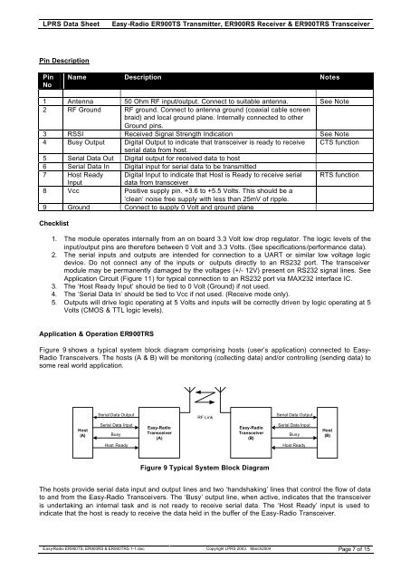
LPRS Data SheetEasy -Radio ER900TS Transmitter, ER900RS Receiver & ER900TRS <strong>Transceiver</strong>Pin DescriptionPinNoName Description Notes1 Antenna 50 Ohm RF input/output. Connect to suitable antenna. See Note2 RF Ground RF ground. Connect to antenna ground (coaxial cable screenbraid) and local ground plane. Internally connected to otherGround pins.3 RSSI Received Signal Strength Indication See Note4 Busy Output Digital Output to indicate that transceiver is ready to receive CTS functionserial data from host.5 Serial Data Out Digital output for received data to host6 Serial Data In Digital input for serial data to be transmitted7 Host Ready Digital Input to indicate that Host is Ready to receive serial RTS functionInputdata from transceiver8 Vcc Positive supply pin. +3.6 to +5.5 Volts. This should be a‘clean’ noise free supply with less than 25mV of ripple.9 Ground Connect to supply 0 Volt and ground planeChecklist1. The module operates internally from an on board 3.3 Volt low drop regulator. The logic levels of theinput/output pins are therefore between 0 Volt and 3.3 Volts. (See specifications/performance data).2. The serial inputs and outputs are intended for connection to a UART or similar low voltage logicdevice. Do not connect any of the inputs or outputs directly to an RS232 port. The transceivermodule may be permanently damaged by the voltages (+/- 12V) present on RS232 signal lines. SeeApplication Circuit (Figure 11) for typical connection to an RS232 port via MAX232 interface IC.3. The ‘Host Ready Input’ should be tied to 0 Volt (Ground) if not used.4. The ‘Serial Data In’ should be tied to Vcc if not used. (Receive mode only).5. Outputs will drive logic operating at 5 Volts and inputs will be correctly driven by logic operating at 5Volts (CMOS & TTL logic levels).Application & Operation ER900TRSFigure 9 shows a typical system block diagram comprising hosts (user’s application) connected to Easy-Radio <strong>Transceiver</strong>s. The hosts (A & B) will be monitoring (collecting data) and/or controlling (sending data) tosome real world application.Serial Data OutputRF LinkSerial Data OutputHost(A)Serial Data InputBusyHost ReadyEasy-Radio<strong>Transceiver</strong>(A)Easy-Radio<strong>Transceiver</strong>(B)Serial Data InputBusyHost ReadyHost(B)Figure 9 Typical System Block DiagramThe hosts provide serial data input and output lines and two ‘handshaking’ lines that control the flow of datato and from the Easy-Radio <strong>Transceiver</strong>s. The ‘Busy’ output line, when active, indicates that the transceiveris undertaking an internal task and is not ready to receive serial data. The ‘Host Ready’ input is used toindicate that the host is ready to receive the data held in the buffer of the Easy-Radio <strong>Transceiver</strong>.Easy-Radio ER900TS, ER900RS & ER900TRS 1-1.doc Copyright LPRS 2003. March2004 Page 7 of 15