Cisco 2600 Series Cabling and Setup
Cisco 2600 Series Cabling and Setup
Cisco 2600 Series Cabling and Setup

You also want an ePaper? Increase the reach of your titles
YUMPU automatically turns print PDFs into web optimized ePapers that Google loves.
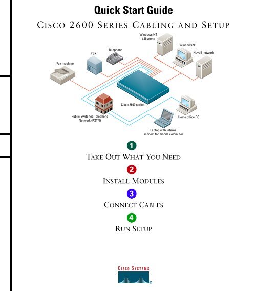
Quick Start GuideC ISCO <strong>2600</strong> SERIES CABLING AND SETUPPBXTelephoneWindows NT4.0 serverWindows 95Novell networkFax machine<strong>Cisco</strong> <strong>2600</strong> seriesPublic Switched TelephoneNetwork (PSTN)Home office PCLaptop with internalmodem for mobile commuter1TAKE OUT WHAT YOU NEED2INSTALL MODULES3CONNECT CABLES4RUN SETUP5
POWER RPS ACTIVITY1Take Out What You Need<strong>Cisco</strong> <strong>2600</strong> series router<strong>Cisco</strong> <strong>2600</strong> SERIESBlack power cableOpen Me First Pouch<strong>Cisco</strong> <strong>2600</strong> <strong>Series</strong> <strong>Cabling</strong> <strong>and</strong> <strong>Setup</strong> quick start guide (thispublication)Software Configuration Guide (for <strong>Cisco</strong> 3600 series <strong>and</strong><strong>Cisco</strong> <strong>2600</strong> series routers)ConfigurationGuide QuickReferenceGuideLight-blue console cable with an RJ-45 connector1Yellow Ethernet cable(s)(one or two, quantity depends on your router model)Purple Token Ring cable (if required)RJ-45-to-DB-9 serial connector (if required)
1Take Out What You Need (continued)Open If Needed PouchBlack auxiliary port cable<strong>Cisco</strong> <strong>2600</strong> <strong>Series</strong> Hardware Installation Guide<strong>Cisco</strong> Network Modules Hardware Installation GuideInstallationGuide InstallationGuide<strong>Cisco</strong> WAN Interface Cards Hardware Installation GuideRegulatory Compliance <strong>and</strong> Safety InformationpublicationInstallationGuide SafetyInformationDB-25 modem connector2Rack-mount kitRubber feet setConnector hardware kit
SERIAL 1SERIAL 0SEE MANUAL BEFORE INSTALLATIONWIC2A/SSERIAL 1SERIAL 0SEE MANUAL BEFORE INSTALLATIONWIC2TInstall ModulesCONN CONNCONN CONN100-240V– 1A50/60 Hz 47 WLINK ETHERNET 1 ACT LINK ETHERNET 0 ACT CONSOLE AUXInstalling a Network ModuleUse this procedure, if required, to install anynetwork module in a <strong>Cisco</strong> <strong>2600</strong> series router.Look for a network module in the slot labeled 1 onthe left-rear of the router. If there is a networkmodule already installed, connect the module toyour network using the appropriate cable.If you need to install a network module, follow thisprocedure:1 Use a number 2 Phillips screwdriver to removethe screws that hold the metal plate over thenetwork module slot cover <strong>and</strong> remove the metalcovering plate.2 Hold the network module by the h<strong>and</strong>le <strong>and</strong> linethe module up with the guides on either side ofthe slot.3 Push the module into place until the edgeconnector is securely seated in the connector onthe motherboard. Ensure that each of themodule’s captive screws lines up with its hole inthe chassis.4 Use the number 2 Phillips screwdriver to securethe captive mounting screws into the holes of thechassis.5 Connect the appropriate network modulecable(s) to your network.For information on connecting network modules,refer to the <strong>Cisco</strong> Network Modules HardwareInstallation Guide included in your router package.3
SERIAL 1SERIAL 0SEE MANUAL BEFORE INSTALLATIONWIC2A/SSERIAL 1SERIAL 0SEE MANUAL BEFORE INSTALLATIONWIC2TInstall Modules (continued)CONN CONN100-240V– 1A50/60 Hz 47 WCONN CONNLINK ETHERNET 1 ACT LINK ETHERNET 0 ACT CONSOLE AUXInstalling a WANInterface CardUse this procedure, if required, to install any WANinterface card in a <strong>Cisco</strong> <strong>2600</strong> series router.For information on connecting WAN interfacecards, refer to the <strong>Cisco</strong> WAN Interface CardsHardware Installation Guide included in yourrouter package.4Look for a WAN interface card in the slots labeledW0 <strong>and</strong> W1 on the right-rear of the router. If there isa WAN interface card already installed, connect thecard to the WAN line using the appropriate cable.If you need to install a WAN interface card, followthis procedure:1 Use a number 2 Phillips screwdriver to removethe screws that hold the metal plate over the cardslot cover <strong>and</strong> remove the metal covering plate.2 Hold the WAN interface card by the edges <strong>and</strong>line the card up with the guides on either side ofthe slot.3 Insert the card in the slot <strong>and</strong> push in until it isfirmly seated in the connector <strong>and</strong> the card’sfront panel is flush with the router’s rear panel.4 Use the number 2 Phillips screwdriver to tightenthe captive screws that are in the card.5 Connect the card to the WAN line using theappropriate cable(s).
SERIAL 1SERIAL 0SEE MANUAL BEFORE INSTALLATIONWIC2A/SSERIAL 1SERIAL 0SEE MANUAL BEFORE INSTALLATIONWIC2TConnect CablesCONN CONNCONN CONN100-240V– 1A50/60 Hz 47 WLINK ETHERNET 1 ACT LINK ETHERNET 0 ACT CONSOLE AUXEthernet 10BaseTport (RJ-45)10BaseT cableEthernet hub(sold separately)5Connect the LAN Cable(s)Position the router so you can reach the rear panel.The cables <strong>and</strong> the router’s ports are color-coded tohelp you make the right connections.Depending on the router model, connect your routerto one or two LANs. Your LAN connection can beEthernet, Fast Ethernet, Token Ring, or acombination. (See the hardware installation guidethat accompanied your router for modelconfigurations.)2 Connect the other end of the Ethernet cable to anEthernet hub or switch (not supplied).3 If your router model uses dual Ethernet LANs,repeat Step 1 <strong>and</strong> Step 2 for the second EthernetLAN connection (ETHERNET 0/1).Connect the Ethernet Cable(s)1 Connect the yellow Ethernet cable to the yellow10BaseT port labeled ETHERNET 0/0 on therear panel of your router.
SERIAL 1SERIAL 0SEE MANUAL BEFORE INSTALLATIONWIC2A/SSERIAL 1SERIAL 0SEE MANUAL BEFORE INSTALLATIONWIC2TConnect Cables (continued)CONN CONNCONN CONN100-240V– 1A50/60 Hz 47 WLINK ETHERNET 1 ACT LINK ETHERNET 0 ACT CONSOLE AUXEthernet 10/100BaseTport (RJ-45)10/100BaseT cable6Ethernet hub(sold separately)Connect the Fast Ethernet Cable(s)1 Connect the yellow Ethernet cable to theyellow 10/100BaseT port labeled10/100 ETHERNET 0/0 on the rear panel ofyour router.2 Connect the other end of the Ethernet cable to anEthernet hub or switch (not supplied).3 If your router model uses dual Fast EthernetLANs, repeat Step 1 <strong>and</strong> Step 2 for the secondEthernet LAN connection(10/100 ETHERNET 0/1).
PWR MODETXSTACKFAULTRX ATTACHSERIAL 1SERIAL 0SEE MANUAL BEFORE INSTALLATIONEIA 232RESET SYSREQWIC2A/SSERIAL 1SERIAL 0SEE MANUAL BEFORE INSTALLATIONWIC2TConnect Cables (continued)CONN CONNCONN CONN100-240V– 1A50/60 Hz 47 WLINK TOKEN RING 0/0 ACT LINK ETHERNET 0 ACT CONSOLEAUXUnshieldedToken Ring cableToken Ring UTPport (RJ-45)1 2 3 4 5 6 7 8 9 10 11 12 13 14 15 16 17 18 19 20RJ-45twisted-pairCatalyst 3900(sold separately)7Connect the Token Ring Cable1 Depending on the router model, connect thepurple Token Ring cable to the RJ-45 portlabeled TOKEN RING 0/0 on the rear panel ofthe router.2 Connect the other end of the Token Ring cableto a switch such as the <strong>Cisco</strong> Catalyst 3900 (notincluded), or to your Token Ring network.
SERIAL 1SERIAL 0SEE MANUAL BEFORE INSTALLATIONWIC2A/SSERIAL 1SERIAL 0SEE MANUAL BEFORE INSTALLATIONWIC2TConnect Cables (continued)CONN CONNCONN CONN100-240V– 1A50/60 Hz 47 WLINK ETHERNET 1 ACT LINK ETHERNET 0CONSOLEAUXConsole port(RJ-45)RJ-45-to-DB-9 orRJ-45-to-DB-25 adapter8Connect the Console Cable1 Connect the light-blue console cable to thelight-blue port labeled CONSOLE on the rearpanel of the router.2 Connect the other end of the light-blue consolecable to an RJ-45 adapter.Use either the RJ-45-to-DB-9 adapter or theRJ-45-to-DB-25 adapter, depending on yourlocal terminal or PC.Note: The RJ-45-to-DB-25 adapter can bepurchased from <strong>Cisco</strong> (<strong>Cisco</strong> part number29-0810-01).3 Attach the adapter to a serial port on a terminalor PC running emulation software to allowrouter configuration.
SERIAL 1SERIAL 0SEE MANUAL BEFORE INSTALLATIONWIC2A/SSERIAL 1SERIAL 0SEE MANUAL BEFORE INSTALLATIONWIC2TConnect Cables (continued)CONN CONNCONN CONN100-240V– 1A50/60 Hz 47 WLINK ETHERNET 1 ACT LINK ETHERNET 0 ACT CONSOLE AUXPower switchPower outletConnect Power <strong>and</strong>Turn On the Router1 Connect the black power cord to the powerconnector on the rear panel of the router.92 Connect the other end of the power cord to theelectrical outlet.3 Turn ON the router by pressing the ON/OFFswitch on the rear panel.The power LED on the front panel should be on.Your router is now operational.You are now finished with physical installation ofthe router.See the next section on using the initial configurationdialog (also called the setup script) in the SystemConfiguration Dialog to configure your router.
Run <strong>Setup</strong>You can configure your router manually using the setup script in the System Configuration Dialog. The setupscript prompts you to enter values appropriate for your router <strong>and</strong> network. Many prompts include defaultanswers, shown in square brackets following the question. Enter your response, or press Return to accept thedefault answer.Note: You can request help at any time by entering a question mark (?) at a setup prompt. If you make amistake, you can exit <strong>and</strong> run the System Configuration Dialog again. Press Ctrl-c, <strong>and</strong> type setup at theprivileged EXEC mode (enable) prompt (<strong>2600</strong>#).See the Software Configuration Guide (for <strong>Cisco</strong> 3600 series <strong>and</strong> <strong>Cisco</strong> <strong>2600</strong> series routers) for completeinformation on using the setup script to configure the router.Step 1Step 2Connect a console to your router. If you need help, see the “Connect the Console Cable” section onpage 8.Power ON the router.10Messages will begin to appear in your terminal emulation program window.CautionDo not press any keys on the keyboard until the messages stop. Any keys pressed during thistime are interpreted as the first comm<strong>and</strong> typed. It will take a few minutes for the messages to stop.The beginnings of the messages look similar to the following.Note: The messages vary, depending on the <strong>Cisco</strong> IOS software release <strong>and</strong> feature set you selected. The screendisplays in this section are for reference only <strong>and</strong> might not exactly reflect the messages on your screen.System Bootstrap, Version 11.3(1)XA, PLATFORM SPECIFIC RELEASED SOFTWARE (fc1)Copyright (c) 1998 by cisco Systems, Inc.C<strong>2600</strong> platform with 32768 Kbytes of main memoryStep 3When the following prompt appears, press Return to accept the default entry (yes) in square brackets:Would you like to enter the initial configuration dialog? [yes]:At any point you may enter a question mark?' for help.Use ctrl-c to abort configuration dialog at any prompt.Default settings are in square brackets '[]'.
Run <strong>Setup</strong> (continued)Step 4When the following prompt appears, press Return to see the current interface summary:First, would you like to see the current interface summary? [yes]:Any interface listed with OK? value "NO" does not have a valid configurationInterface IP-Address OK? Method Status ProtocolEthernet0/0 unassigned NO unset up upSerial0/0 unassigned NO unset up downEthernet0/1 unassigned NO unset up upSerial0/1 unassigned NO unset up downSerial0/2 unassigned NO unset up downStep 5 Enter a host name for the router (this example uses <strong>2600</strong>):Configuring global parameters:Enter host name [Router]: <strong>2600</strong>The enable secret is a password used to protect access to privileged EXEC <strong>and</strong>configuration modes. This password, after entered, becomes encrypted in the configuration.Step 6Enter an enable secret password. This password is encrypted (more secure) <strong>and</strong> cannot be seen whenviewing the configuration:11Enter enable secret: xxxxStep 7The enable password is used when there is no enable secret <strong>and</strong> when using older software<strong>and</strong> some boot images.Enter an enable password that is different from the enable secret password. This password is notencrypted (less secure) <strong>and</strong> can be seen when viewing the configuration:Enter enable password: guessmeStep 8The virtual terminal password is used to protect access to the router over a networkinterface.Enter the virtual terminal password, which prevents unauthenticated access to the router throughports other than the console port:Enter virtual terminal password: guessagain
Run <strong>Setup</strong> (continued)Step 9Respond to the following prompts as appropriate for your network:Configure SNMP Network Management? [yes]:Community string [public]:Configure LAT? [no]:Configure AppleTalk? [no]: yesMultizone networks? [no]: yesConfigure DECnet? [no]:Configure IP? [yes]:Configure IGRP routing? [yes]:Your IGRP autonomous system number [1]: 15Note:If you answer no to IGRP, you will be prompted to configure RIP.12Step 10Step 11Configure CLNS? [no]:Configure IPX? [no]: yesConfigure Vines? [no]:Configure XNS? [no]:Configure Apollo? [no]:Configure bridging? [no]:From this point on in the setup script, the prompts you see vary depending on the interface modulesin place in your router. Complete the setup steps for your router interface modules.When you have completed the initial configuration dialog, messages appear describing theconfiguration comm<strong>and</strong> script.A setup script prompt asks if you want to save this configuration. If you answer no, the configurationinformation you entered is not saved, <strong>and</strong> you return to the <strong>Cisco</strong> <strong>2600</strong> router enable prompt (<strong>2600</strong>#).Type setup to return to the System Configuration Dialog.If you answer yes, the configuration is saved <strong>and</strong> you are returned to the router prompt (<strong>2600</strong>>)(prompt depends on host name variable).Use this configuration? [yes/no]: yesBuilding configuration...Use the enabled mode 'configure' comm<strong>and</strong> to modify this configuration.Press RETURN to get started!%LINK-3-UPDOWN: Interface Ethernet0/0, changed state to up%LINK-3-UPDOWN: Interface Ethernet0/1, changed state to up%LINK-3-UPDOWN: Interface Serial0/0, changed state to up%LINK-3-UPDOWN: Interface Serial0/1, changed state to down%LINK-3-UPDOWN: Interface Serial0/2, changed state to down%LINK-3-UPDOWN: Interface Serial1/0, changed state to up%LINK-3-UPDOWN: Interface Serial1/1, changed state to down%LINK-3-UPDOWN: Interface Serial1/2, changed state to down
Run <strong>Setup</strong> (continued)Step 12When the messages stop displaying on your screen, press Return to get the prompt (prompt dependson host name variable):<strong>2600</strong>>The <strong>2600</strong>> prompt indicates that you are now at the comm<strong>and</strong>-line interface (CLI) <strong>and</strong> you have justcompleted a basic router configuration.13
Corporate Headquarters<strong>Cisco</strong> Systems, Inc.170 West Tasman DriveSan Jose, CA 95134-1706USAhttp://www.cisco.comTel: 408 526-4000800 553-NETS (6387)Fax: 408 526-4100European Headquarters<strong>Cisco</strong> Systems Europe s.a.r.l.Parc Evolic, Batiment L1/L216 Avenue du QuebecVillebon, BP 70691961 Courtaboeuf CedexFrancehttp://www-europe.cisco.comTel: 33 1 69 18 61 00Fax: 33 1 69 28 83 26AmericasHeadquarters<strong>Cisco</strong> Systems, Inc.170 West Tasman DriveSan Jose, CA 95134-1706USAhttp://www.cisco.comTel: 408 526-7660Fax: 408 527-0883Asia HeadquartersNihon <strong>Cisco</strong> Systems K.K.Fuji Building, 9th floor3-2-3 MarunouchiChiyoda-ku, Tokyo 100Japanhttp://www.cisco.comTel: 81 3 5219 6250Fax: 81 3 5219 6001<strong>Cisco</strong> Systems has more than 200 offices in the following countries. Addresses, phone numbers, <strong>and</strong> fax numbers are listed on the<strong>Cisco</strong> Connection Online Web site at http://www.cisco.com/offices.Argentina • Australia • Austria • Belgium • Brazil • Canada • Chile • China • Colombia • Costa Rica • Croatia • Czech Republic • Denmark • Dubai, UAEFinl<strong>and</strong> • France • Germany • Greece • Hong Kong • Hungary • India • Indonesia • Irel<strong>and</strong> • Israel • Italy • Japan • Korea • Luxembourg • MalaysiaMexico • The Netherl<strong>and</strong>s • New Zeal<strong>and</strong> • Norway • Peru • Philippines • Pol<strong>and</strong> • Portugal • Puerto Rico • Romania • Russia • Saudi Arabia • SingaporeSlovakia • Slovenia • South Africa • Spain • Sweden • Switzerl<strong>and</strong> • Taiwan • Thail<strong>and</strong> • Turkey • Ukraine • United Kingdom • United States • VenezuelaCopyright © 1999, <strong>Cisco</strong> Systems, Inc. All rights reserved. Access Registrar, AccessPath, Any to Any, AtmDirector, CCDA, CCDE, CCDP, CCIE, CCNA, CCNP, CCSI, CD-PAC, the <strong>Cisco</strong> logo, <strong>Cisco</strong> CertifiedInternetwork Expert logo, <strong>Cisco</strong>Link, the <strong>Cisco</strong> Management Connection logo, the <strong>Cisco</strong> NetWorks logo, the <strong>Cisco</strong> Powered Network logo, <strong>Cisco</strong> Systems Capital, the <strong>Cisco</strong> Systems Capital logo, <strong>Cisco</strong> SystemsNetworking Academy, the <strong>Cisco</strong> Systems Networking Academy logo, the <strong>Cisco</strong> Technologies logo, ConnectWay, ControlStream, Fast Step, FireRunner, GigaStack, IGX, Internet Quotient, Kernel Proxy, MGX,Natural Network Viewer, NetSonar, Network Registrar, Packet, PIX, Point <strong>and</strong> Click Internetworking, Policy Builder, Precept, RouteStream, Secure Script, ServiceWay, SlideCast, SMARTnet, StreamView, The Cell,TrafficDirector, TransPath, ViewRunner, VirtualStream, VisionWay, VlanDirector, Workgroup Director, <strong>and</strong> Workgroup Stack are trademarks; Changing the Way We Work, Live, Play, <strong>and</strong> Learn, Empowering theInternet Generation, The Internet Economy, <strong>and</strong> The New Internet Economy are service marks; <strong>and</strong> ASIST, BPX, Catalyst, <strong>Cisco</strong>, <strong>Cisco</strong> IOS, the <strong>Cisco</strong> IOS logo, <strong>Cisco</strong> Systems, the <strong>Cisco</strong> Systems logo, the <strong>Cisco</strong>Systems <strong>Cisco</strong> Press logo, Enterprise/Solver, EtherChannel, EtherSwitch, FastHub, FastLink, FastPAD, FastSwitch, GeoTel, IOS, IP/TV, IPX, LightStream, LightSwitch, MICA, NetRanger, Registrar, StrataView Plus,Stratm, TeleRouter, <strong>and</strong> VCO are registered trademarks of <strong>Cisco</strong> Systems, Inc. <strong>and</strong>/or its affiliates in the U.S. <strong>and</strong> certain other countries. All other trademarks mentioned in this document are the property of theirrespective owners. The use of the word partner does not imply a partnership relationship between <strong>Cisco</strong> <strong>and</strong> any of its resellers. (9908R)Printed in the USA on recycled paper containing 10% postconsumer waste.DOC-<strong>2600</strong>CS-QSG=78-5126-04