
Create successful ePaper yourself
Turn your PDF publications into a flip-book with our unique Google optimized e-Paper software.
Back to Contents pages<br />
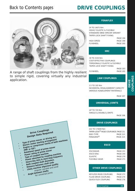
A range of shaft couplings from the highly resilient<br />
to simple rigid, covering virtually any industrial<br />
application.<br />
Drive Couplings<br />
Design Data Required<br />
• Type of prime mover, or driving m/c<br />
• Electric motor starting arrangement<br />
• Engine or compressor inertia of both machines<br />
(MR 2 or GD 2 )<br />
• Rotational speed of prime mover<br />
• Power rating of prime mover<br />
• Type of coupled machine<br />
• Power absorbed by coupling machine<br />
• Hours/day duty & start/stop frequency<br />
• Both coupled shaft diameters<br />
• Distance between shaft ends<br />
• Likely machine alignment quality<br />
angular, parallel and axial<br />
• Angle between shafts<br />
for universal joints<br />
<strong>DRIVE</strong> <strong>COUPLINGS</strong><br />
FENAFLEX<br />
24 TO 14675 Nm<br />
HIGHLY ELASTIC & FLEXIBLE<br />
STANDARD DBSE SPACER VARIANT<br />
TAPER LOCK SHAFT FIXING<br />
PAGE 194<br />
HIGH SPEED PAGE 199<br />
FLYWHEEL PAGE 200<br />
HRC<br />
30 TO 3150 Nm<br />
COST-EFFECTIVE <strong>COUPLINGS</strong><br />
TORSIONALLY ELASTIC & FLEXIBLE<br />
TAPER LOCK SHAFT FIXING<br />
PAGE 203<br />
FLYWHEEL PAGE 205<br />
JAW <strong>COUPLINGS</strong><br />
3.5 TO 105 Nm<br />
INCIDENTAL MISALIGNMENT CAPACITY<br />
VARIOUS HUB/ELEMENT MATERIALS<br />
UNIVERSAL JOINTS<br />
UP TO 720 Nm<br />
SINGLE & DOUBLE JOINTS<br />
<strong>DRIVE</strong> <strong>COUPLINGS</strong><br />
PAGE 207<br />
PAGE 208<br />
222 TO 174000 Nm<br />
TAPER-LOCK ® RIGID <strong>COUPLINGS</strong> PAGE 211<br />
DISC-TYPE PAGE 212<br />
FENAGRID ® PAGE 214<br />
ESCO<br />
ESCOGEAR PAGE 221<br />
ESCO DISC PAGE 244<br />
ELASTIC PAGE 270<br />
FLEXIBLE GEAR PAGE 271<br />
OTHER <strong>DRIVE</strong> <strong>COUPLINGS</strong><br />
KEYLESS RIGID COUPLING PAGE 272<br />
FLUID <strong>DRIVE</strong> COUPLING PAGE 274<br />
QUICK-FLEX COUPLING PAGE 276<br />
Drive Couplings 193<br />
<strong>DRIVE</strong><br />
<strong>COUPLINGS</strong>
<strong>DRIVE</strong><br />
<strong>COUPLINGS</strong><br />
Fenaflex<br />
194 Drive Couplings<br />
Couplings<br />
Fenaflex couplings provide all the desirable features of an ideal flexible coupling, including Taper-Lock ® fixing.<br />
The Fenaflex coupling is a "torsionally elastic" coupling offering versatility to designers and engineers with a<br />
choice of flange combinations to suit most applications.<br />
The flanges are available in either F or H Taper-Lock ® fitting or pilot bored, which can be bored to the required size.<br />
With the addition of a spacer the coupling can be used to accommodate standard distances between shaft<br />
ends and thereby facilitate pump maintenance.<br />
Fenaflex couplings can accommodate simultaneous maximum misalignment in all planes without imposing<br />
undue loads on adjacent bearings and the excellent shock-absorbing properties of the flexible tyre reduce<br />
vibration and torsional oscillations.<br />
Fenaflex tyres are available in natural rubber compounds for use in ambient temperatures between –50OC and +50OC. Chloroprene rubber compounds are available for use in adverse operating conditions (e.g. oil or<br />
grease contamination) and can be used in temperatures of –15OC to +70OC. The chloroprene compound<br />
should also be used when fire-resistance and anti-static (F.R.A.S.) properties are required.<br />
SELECTION<br />
(a) Service Factor<br />
Determine the required Service Factor<br />
from table below.<br />
(b) Design Power<br />
Multiply the normal running power by<br />
the service factor. This gives the design<br />
power which is used as a basis for<br />
selecting the coupling.<br />
(c) Coupling Size<br />
Refer to Power Ratings table<br />
(page 195) and from the appropriate<br />
speed read across until a power greater<br />
than that required in step (b) is found.<br />
The size of Fenaflex coupling required<br />
is given at the head of that column.<br />
(d) Bore Size<br />
Check from Dimensions table<br />
(page 196) that chosen flanges can<br />
accommodate required bores.<br />
SERVICE FACTORS<br />
R<br />
SPECIAL CASES<br />
For applications where substantial shock, vibration and torque<br />
fluctuations occur, and for reciprocating machines (e.g. internal<br />
combustion engines, piston pumps and compressors) refer to<br />
Fenner Power Transmission Distributor with full machine details<br />
for analysis.<br />
EXAMPLE<br />
A Fenaflex coupling is required to transmit<br />
45kW from an A.C. electric motor which<br />
runs at 1440 rev/min to a rotary screen for<br />
12 hours per day. The motor shaft is 60mm<br />
diameter and the screen shaft is 55mm<br />
diameter. Taper Lock is required.<br />
(a) Service Factor<br />
The appropriate service factor is 1,4.<br />
(b) Design Power<br />
Design power = 45 x 1,4 = 63kW.<br />
(c) Coupling Size<br />
By reading across from 1440 rev/min in<br />
the power ratings table the first power<br />
figure to exceed the required 63kW in<br />
step (b) is 75,4kW. The size of coupling<br />
is F90 Fenaflex.<br />
(d) Bore Size<br />
By referring to the dimensions table it<br />
can be seen that both shaft diameters<br />
fall within the bore range available.<br />
Electric Motors<br />
Steam Turbines<br />
Type of Driving Unit<br />
Internal Combustion Engines†<br />
Steam Engines<br />
Water Turbines<br />
Hours per day duty Hours per day duty<br />
10 and over 10 over 10 and over 10 over<br />
Type of Driven Machine<br />
CLASS 1<br />
Brewing machinery, Centrifugal compressors and pumps.<br />
under to 16 incl. 16 under to 16 incl. 16<br />
Belt conveyors, Dynamometers, Lineshafts, Fans up to 7,5kW<br />
Blowers and exhausters (except positive displacement),<br />
Generators.<br />
CLASS 2*<br />
Agitators, Clay working machinery, General machine tools,<br />
0,8 0,9 1,0 1,3 1,4 1,5<br />
paper mill beaters and winders, Rotary pumps, Rubber extruders,<br />
Rotary screens,Textile machinery, Marine propellors and Fans<br />
over 7,5kw.<br />
CLASS 3*<br />
Bucket elevators, Cooling tower fans, Piston compressors and<br />
1,3 1,4 1,5 1,8 1,9 2,0<br />
pumps, Foundry machinery, Metal presses, Paper mill calenders,<br />
Hammer mills, Presses and pulp grinders, Rubber calenders,<br />
Pulverisers and Positive displacement blowers.<br />
CLASS 4*<br />
1,8 1,9 2,0 2,3 2,4 2,5<br />
Reciprocating conveyors, Gyratory crushers, Mills (ball, pebble<br />
and rod), Rubber machinery (Banbury mixers and mills) and<br />
Vibratory screens.<br />
2,3 2,4 2,5 2,8 2,9 3,0<br />
* It is recommended that keys (with top clearance if in Taper-Lock ® bushes) are fitted on application where load fluctuation is expected.<br />
† Couplings for use with internal combustion engines may require special consideration, refer to pages 200 and 205.
POWER RATINGS (kW)<br />
R<br />
Fenaflex Couplings – Power Ratings<br />
Coupling Size<br />
Speed<br />
rev/min F40 F50 F60 F70 F80 F90 F100 F110 F120 F140 F160 F180 F200 F220 F250<br />
100 0,25 0,69 11,33 2,62 113,93 5,24 7,07 9,16 113,9 124,3 139,5 165,7 97,6 121 154<br />
200 0,50 1,38 12,66 5,24 117,85 110,5 114,1 118,3 127,9 148,7 179,0 131 195 243 307<br />
300 0,75 2,07 13,99 7,85 111,8 115,7 121,2 127,5 141,8 173,0 118 197 293 364 461<br />
400 1,01 2,76 15,32 10,5 15,7 120,9 128,3 136,6 155,7 197,4 158 263 1391 486 615<br />
500 1,26 3,46 16,65 13,1 19,6 126,2 135,3 145,8 169,6 122 197 328 1488 607 768<br />
600 1,51 4,15 17,98 15,7 23,6 131,4 142,4 155,0 183,6 146 237 394 1586 729 922<br />
700 1,76 4,84 19,31 18,3 27,5 136,6 149,5 164,1 197,5 170 276 460 1684 850 1076<br />
720 1,81 4,98 19,57 18,8 28,3 137,7 150,9 166,0 100 175 284 473 1703 875 1106<br />
800 2,01 5,53 10,6 20,9 31,4 141,9 156,5 173,3 111 195 316 525 1781 972 1229<br />
900 2,26 6,22 12,0 23,6 35,3 147,1 163,6 182,5 125 219 355 591 1879 1093 1383<br />
960 2,41 6,63 12,8 25,1 37,7 150,3 167,9 188,0 134 234 379 630 1937 1166 1475<br />
1000 2,51 6,91 13,3 26,2 39,3 152,4 170,7 191,6 139 243 395 657 1976 1215 1537<br />
1200 3,02 8,29 16,0 31,4 47,1 162,8 184,8 110 167 292 474 788 1172<br />
1400 3,52 9,68 18,6 36,6 55,0 173,3 199,0 128 195 341 553 919<br />
1440 3,62 9,95 19,1 37,7 56,5 175,4 102 132 201 351 568 945<br />
1600 4,02 11,1 21,3 41,9 62,8 183,8 113 147 223 390 632<br />
1800 4,52 12,4 23,9 47,1 70,7 194,2 127 165 251 438<br />
2000 5,03 13,8 26,6 52,4 78,5 105,5 141 183 279<br />
2200 5,53 15,2 29,3 57,6 86,4 115 155 202<br />
2400 6,03 16,6 31,9 62,8 94,2 126 170<br />
2600 6,53 18,0 34,6 68,1 102 136 184<br />
2800 7,04 19,4 37,2 73,3 110 147<br />
2880 7,24 19,9 38,3 75,4 113 151<br />
3000 7,54 20,7 39,9 78,5 118 157<br />
3600 9,05 24,9 47,9 94,2<br />
PHYSICAL CHARACTERISTICS – FLEXIBLE TYRES<br />
Coupling Size<br />
The figures in heavier type are for standard<br />
motor speeds. All these power ratings are<br />
calculated at constant torque. For speeds<br />
below 100 rev/min and intermediate<br />
speeds use nominal torque ratings.<br />
Characteristics F40 F50 F60 F70 F80 F90 F100 F110 F120 F140 F160 F180 F200 F220 F250<br />
Maximum speed rev/min 4500 4500 4000 3600 3100 3000 2600 2300 2050 1800 1600 1500 1300 1100 1000<br />
Nominal Torque Nm TK N 24 66 127 250 375 500 675 875 1330 2325 3770 6270 9325 11600 14675<br />
Maximum Torque Nm TK MAX 64 160 318 487 759 1096 1517 2137 3547 5642 9339 16455 23508 33125 42740<br />
Torsional Stiffness Nm/ O 5 13 26 41 63 91 126 178 296 470 778 1371 1959 2760 3562<br />
Max, parallel misalignment mm 1,1 1,3 1,6 1,9 2,1 2,4 2,6 2,9 3,2 3,7 4,2 4,8 5,3 5,8 6,6<br />
Maximum end float mm ± 1,3 1,7 2,0 2,3 2,6 3,0 3,3 3,7 4,0 4,6 5,3 6,0 6,6 7,3 8,2<br />
Approximate mass, kg<br />
Alternating Torque ± Nm<br />
0,1 0,3 0,5 0,7 1,0 1,1 1,1 1,4 2,3 2,6 3,4 7,7 8,0 10 15<br />
@ 10Hz TKW 11 26 53 81 127 183 252 356 591 940 1556 2742 3918 5521 7124<br />
Resonance Factor V R 7 7 7 7 7 7 7 7 7 7 7 7 7 7 7<br />
Damping Coefficient Ψ 0,9 0,9 0,9 0,9 0,9 0,9 0,9 0,9 0,9 0,9 0,9 0,9 0,9 0,9 0,9<br />
Maximum torque figures should be regarded as short duration overload ratings for use in such circumstances as direct-on-line starting.<br />
All flexible tyres have an angular misalignment capacity up to 4 o .<br />
FLEXIBLE TYRE CODE NUMBERS<br />
Unless otherwise specified Fenaflex<br />
flexible tyres will be supplied in a<br />
natural rubber compound which is<br />
suitable for operation in temperatures –<br />
50 O C to +50 O C. A chloroprene compound<br />
is available which is Fire Resistant and<br />
Anti-Static (F.R.A.S) and has greater<br />
resistance to heat and oil.<br />
This is suitable for operation in<br />
temperatures –15 O C to +70 O C. For<br />
temperatures outside these ranges –<br />
consult Fenner Power Transmission<br />
Distributor.<br />
Coupling<br />
Size<br />
F40*<br />
F50*<br />
F60*<br />
F70<br />
F80<br />
F90<br />
F100<br />
F110<br />
F120<br />
F140<br />
F160<br />
F180<br />
F200<br />
F220<br />
F250<br />
M<br />
Dimension<br />
(mm)<br />
11<br />
12,5<br />
16,5<br />
11,5<br />
12,5<br />
13,5<br />
13,5<br />
12,5<br />
14,5<br />
16<br />
15<br />
23<br />
24<br />
27,5<br />
29,5<br />
Gap<br />
Between<br />
Tyre Ends<br />
(mm)<br />
2<br />
2<br />
2<br />
3<br />
3<br />
3<br />
3<br />
3<br />
3<br />
5<br />
5<br />
6<br />
6<br />
6<br />
6<br />
Clamping<br />
Screw<br />
Torque<br />
(Nm)<br />
15<br />
15<br />
15<br />
24<br />
24<br />
40<br />
40<br />
40<br />
50<br />
55<br />
80<br />
105<br />
120<br />
165<br />
165<br />
Screw<br />
Size<br />
M6<br />
M6<br />
M6<br />
M8<br />
M8<br />
M10<br />
M10<br />
M10<br />
M12<br />
M12<br />
M16<br />
M16<br />
M16<br />
M20<br />
M20<br />
*Hexagonal socket caphead clamping screws on these sizes.<br />
Drive Couplings 195<br />
<strong>DRIVE</strong><br />
<strong>COUPLINGS</strong>
<strong>DRIVE</strong><br />
<strong>COUPLINGS</strong><br />
R<br />
Fenaflex Couplings – Dimensions<br />
FLANGES<br />
DIMENSIONS OF FENAFLEX FLANGES TYPES B, F & H<br />
Bush<br />
Max Bore Types F & H Type B<br />
Screw<br />
Size Type No.<br />
# Metric Inch L E J† L E<br />
over<br />
Key<br />
A C D F G§ M¶ Mass*<br />
(kg)<br />
Inertia*<br />
(kgm2 )<br />
F40 B – 32 – – – 29 33 22 M5 104 82 – – – 11 0,8 0, 00074<br />
F40 F 1008 25 1 " 33 22 29 – – – 104 82 – – – 11 0,8 0, 00074<br />
F40 H 1008 25 1 " 33 22 29 – – – 104 82 – – – 11 0,8 0, 00074<br />
F50 B – 38 – – – 38 45 32 M5 133 100 79 – – 12 ,5 1,2 0, 00115<br />
F50 F 1210 32 1 1 F50 H 1210 32<br />
/4"<br />
1<br />
38 25 38 – – – 133 100 79 – – 12 ,5 1,2 0, 00115<br />
1 /4" 38 25 38 – – – 133 100 79 – – 12 ,5 1,2 0, 00115<br />
F60<br />
F60<br />
B<br />
F<br />
–<br />
1610<br />
45<br />
42<br />
–<br />
1<br />
– – 38 55 38 M6 165 125 70 – – 16 ,5 2,0 0, 0052<br />
5 /8" 42 25 38 – – – 165 125 103 – – 16 ,5 2,0 0, 0052<br />
F60 H 1610 42 1 5 /8" 42 25 38 – – – 165 125 103 – – 16 ,5 2,0 0, 0052<br />
F70 B – 50 – – – – 47 35 M10 187 144 80 50 13 11 ,5 3,1 0, 009<br />
F70<br />
F70<br />
F<br />
H<br />
2012<br />
1610<br />
50<br />
42<br />
2 "<br />
1<br />
44 32 42 – – – 187 144 80 50 13 11 ,5 3,1 0, 009<br />
5 /8" 42 25 38 – – – 187 144 80 50 13 11 ,5 3,0 0, 009<br />
F80<br />
F80<br />
B<br />
F<br />
–<br />
2517<br />
60<br />
60<br />
–<br />
2<br />
– – – 55 42 M10 211 167 98 54 16 12 ,5 4,9 0, 018<br />
1 /2" 58 45 48 – – – 211 167 97 54 16 12 ,5 4,9 0, 018<br />
F80 H 2012 50 2 " 45 32 42 – – – 211 167 98 54 16 12 ,5 4,6 0, 017<br />
F90 B – 70 – – – – 63,5 49 M12 235 188 112 60 16 13 ,5 7,1 0, 032<br />
F90 F 2517 60 2 1 /2" 59,5 45 48 – – – 235 188 108 60 16 13 ,5 7,0 0, 031<br />
F90 H 2517 60 2 1 /2" 59,5 45 48 – – – 235 188 108 60 16 13 ,5 7,0 0, 031<br />
F100 B – 80 – – – – 70,5 56 M12 254 216 125 62 16 13 ,5 9,9 0, 055<br />
F100<br />
F100<br />
F<br />
H<br />
3020<br />
2517<br />
75<br />
60<br />
3 "<br />
2<br />
65,5 51 55 – – – 254 216 120 62 16 13 ,5 9,9 0, 055<br />
1 /2" 59,5 45 48 – – – 254 216 113 62 16 13 ,5 9,4 0, 054<br />
F110<br />
F110<br />
B<br />
F<br />
–<br />
3020<br />
90<br />
75<br />
–<br />
3 "<br />
–<br />
63,5<br />
–<br />
51<br />
–<br />
55<br />
75,5<br />
–<br />
63<br />
–<br />
M12<br />
–<br />
279<br />
279<br />
233<br />
233<br />
128<br />
134<br />
62<br />
62<br />
16<br />
16<br />
12 ,5<br />
12 ,5<br />
12,5<br />
11,7<br />
0, 081<br />
0, 078<br />
F110 H 3020 75 3 " 63,5 51 55 – – – 279 233 134 62 16 12 ,5 11,7 0, 078<br />
F120 B – 100 – – – – 84,5 70 M16 314 264 143 67 16 14 ,5 16,9 0, 137<br />
F120 F 3525 100 4 " 79,5 65 67 – – – 314 264 140 67 16 14 ,5 16,5 0, 137<br />
F120 H 3020 75 3 " 65,5 51 55 – – – 314 264 140 67 16 14 ,5 15,9 0, 130<br />
F140 B – 130 – – – – 110,5 94 M20 359 311 178 73 17 16 22,2 0, 254<br />
F140<br />
F140<br />
F<br />
H<br />
3525<br />
3525<br />
100<br />
100<br />
4 "<br />
4 "<br />
81,5<br />
81,5<br />
65<br />
65<br />
67<br />
67<br />
–<br />
–<br />
–<br />
–<br />
–<br />
–<br />
359<br />
359<br />
311<br />
311<br />
178<br />
178<br />
73<br />
73<br />
17<br />
17<br />
16<br />
16<br />
22,3<br />
22,3<br />
0, 255<br />
0, 255<br />
F160<br />
F160<br />
B<br />
F<br />
–<br />
4030<br />
140<br />
115<br />
–<br />
4<br />
– – – 117 102 M20 402 345 187 78 19 15 35,8 0, 469<br />
1 /2" 92 77 80 – – – 402 345 197 78 19 15 32,5 0, 380<br />
F160 H 4030 115 4 1 /2" 92 77 80 – – – 402 345 197 78 19 15 32,5 0, 380<br />
F180 B – 150 – – – – 137 114 M20 470 398 200 94 19 23 49,1 0, 871<br />
F180 F 4535 125 5 " 112 89 89 – – – 470 398 205 94 19 23 42,2 0, 847<br />
F180 H 4535 125 5 " 112 89 89 – – – 470 398 205 94 19 23 42,2 0, 847<br />
F200 B – 150 – – – – 138 114 M20 508 429 200 103 19 24 58,2 1, 301<br />
F200<br />
F200<br />
F<br />
H<br />
4535<br />
4535<br />
125<br />
125<br />
5 "<br />
5 "<br />
113<br />
113<br />
89<br />
89<br />
89<br />
89<br />
–<br />
–<br />
–<br />
–<br />
–<br />
–<br />
508<br />
508<br />
429<br />
429<br />
205<br />
205<br />
103<br />
103<br />
19<br />
19<br />
24<br />
24<br />
53,6<br />
53,6<br />
1, 281<br />
1, 281<br />
F220<br />
F220<br />
B<br />
F<br />
–<br />
5040<br />
160<br />
125<br />
–<br />
5 "<br />
–<br />
129,5<br />
–<br />
102<br />
–<br />
92<br />
154,5<br />
–<br />
127<br />
–<br />
M20<br />
–<br />
562<br />
562<br />
474<br />
474<br />
218<br />
223<br />
118<br />
118<br />
20<br />
20<br />
27 ,5<br />
27 ,5<br />
79,6<br />
72,0<br />
2, 142<br />
2, 104<br />
F220 H 5040 125 5 " 129,5 102 92 – – – 562 474 223 118 20 27 ,5 72,0 2, 104<br />
F250 B – 190 – – – – 161,5 132 M20 628 532 254 125 25 29 ,5 104,0 3, 505<br />
Dimensions in millimetres unless otherwise stated.<br />
§ G is the amount by which clamping screws need to be withdrawn to release tyre.<br />
† J is the wrench clearance to allow for tightening/loosening the bush on the shaft and the clamp ring screws on sizes F40, F50 and F60. The use of a shortened<br />
wrench will allow this dimension to be reduced.<br />
¶ M is half the distance between flanges. Shaft ends, although normally located twice M apart, can project beyond the flanges as shown. In this event<br />
allow sufficient space between shaft ends for end float and misalignment.<br />
* Mass and inertia figures are for single flange with mid range bore and include clamping ring, screws and washers and half tyre.<br />
‡ For pilot bore 'B' flange code as listed.<br />
Flanges are also available finish bored with keyway if required.<br />
Bore must be specified on order.<br />
# Note: On sizes F70, 80, 100 and 120 the 'F' direction bush is larger than that in the 'H'direction.<br />
196 Drive Couplings
Comprising a Fenaflex tyre coupling (size<br />
F40–F140) complete with a spacer flange<br />
designed for use on applications where it is<br />
an advantage to be able to move either<br />
shaft axially without disturbing the driving or<br />
driven machine (e,g, centrifugal pump<br />
rotors), Fenaflex spacer couplings are<br />
primarily designed for standard distance<br />
between shaft end dimensions 100, 140 and<br />
180mm.<br />
DISTANCE BETWEEN SHAFT ENDS<br />
R<br />
Fenaflex Spacer Couplings<br />
SELECTION<br />
1. Select a suitable size of Fenaflex<br />
coupling using the method shown on<br />
page 194. Read down the first column<br />
in table below and locate the size of<br />
coupling selected.<br />
2. Read across until the required distance<br />
between shaft ends can be<br />
accommodated.<br />
3. Note the required spacer coupling<br />
designation at head of column.<br />
4. Check from the Spacer Coupling<br />
Dimensions table below that the<br />
selected spacer/coupling combination<br />
can accommodate the machine shaft<br />
size.<br />
Note<br />
Typical order consists of<br />
1 x Spacer 3 x Taper Lock bushes<br />
2 x Fenaflex flanges 1 x Fenaflex tyre<br />
SM12 SM16<br />
Distance between Shaft Ends (mm)<br />
SM25 SM30 SM35<br />
Size 80 (100) 100 140 100 140 180 140 180 140 180<br />
Min Max Min Max Min Max Min Max Min Max Min Max Min Max Min Max Min Max Min Max<br />
F40 80 100 100 113 140 150<br />
F50 100 116 140 156<br />
F60 100 124 140 164<br />
F70 100 114 140 154 180 194<br />
F80 100 117 140 157 180 197<br />
F90 140 158 180 198<br />
F100 140 158 180 198<br />
F110 140 156 180 196<br />
F120 140 160 180 200<br />
F140<br />
Note: Alternative distances between shaft ends may be accommodated. Consult Fenner Power Transmission Distributor.<br />
140 163 180 203<br />
SPACER COUPLING DIMENSIONS<br />
Spacer Max. Bore Fenaflex Max. Bore<br />
Nom Bush Bush<br />
Spacer DBSE Fenaflex Size mm Inch Size mm Inch A B C D E F G H J K L M S T<br />
SM12 80 F40 1210 32 1 1 /4" 1008 25 1 " 104 82 118 83 134 25 14 15 14 6 65 22 77 25<br />
SM12 100 F40 1210 32 1 1 /4" 1008 25 1 " 104 82 118 83 140 25 14 15 14 22 77 22 77 25<br />
SM16 100 F40* 1610 42 1 5 /8" 1008 25 1 " 104 82 127 80 157 25 18 15 14 9 88 22 94 32<br />
SM16 140 F40* 1610 42 1 5 /8" 1008 25 1 " 104 82 127 80 187 25 18 15 14 9 128 22 134 32<br />
SM16 100 F50 1610 42 1 5 /8" 1210 32 1 1 /4" 133 79 127 80 160 25 18 15 14 9 85 25 94 32<br />
SM16 140 F50 1610 42 1 5 /8" 1210 32 1 1 /4" 133 79 127 80 200 25 18 15 14 9 125 25 134 32<br />
SM16 100 F60 1610 42 1 5 /8" 1610 42 1 5 /8" 165 70 127 80 161 25 18 15 14 9 78 33 94 32<br />
SM16 140 F60 1610 42 1 5 /8" 1610 42 1 5 /8" 165 70 127 80 201 25 18 15 14 9 118 33 134 32<br />
SM25 100 F70† 2517 60 2 1 /2" 2012 50 2 " 187 80 178 123 180 45 22 16 14 9 80 23 94 48<br />
SM25 140 F70† 2517 60 2 1 /2" 2012 50 2 " 187 80 178 123 220 45 22 16 14 9 120 23 134 48<br />
SM25 180 F70† 2517 60 2 1 /2" 2012 50 2 " 187 80 178 123 260 45 22 16 14 9 160 23 174 48<br />
SM25 100 F80 2517 60 2 1 /2" 2517 60 2 1 /2" 211 95 178 123 193 45 22 16 14 9 78 25 94 48<br />
SM25 140 F80 2517 60 2 1 /2" 2517 60 2 1 /2" 211 95 178 123 233 45 22 16 14 9 118 25 134 48<br />
SM25 180 F80 2517 60 2 1 /2" 2517 60 2 1 /2" 211 95 178 123 273 45 22 16 14 9 158 25 174 48<br />
SM25 140 F90 2517 60 2 1 /2" 2517 60 2 1 /2" 235 108 178 123 233 45 22 16 14 9 116 27 134 48<br />
SM25 180 F90 2517 60 2 1 /2" 2517 60 2 1 /2" 235 108 178 123 273 45 22 16 14 9 156 27 174 48<br />
SM30 140 F100 3020 75 3 " 3020 75 3 " 254 120 216 146 245 51 29 20 17 9 116 27 134 60<br />
SM30 180 F100 3020 75 3 " 3020 75 3 " 254 120 216 146 285 51 29 20 17 9 156 27 174 60<br />
SM30 140 F110 3020 75 3 " 3020 75 3 " 279 134 216 146 245 51 29 20 17 9 118 25 134 60<br />
SM30 180 F110 3020 75 3 " 3020 75 3 " 279 134 216 146 285 51 29 20 17 9 158 25 174 60<br />
SM35 140 F120† 3525 100 4 " 3525 100 4 " 314 140 248 178 272 63 34 20 17 9 114 29 134 80<br />
SM35 180 F120† 3525 100 4 " 3525 100 4 " 314 140 248 178 312 63 34 20 17 9 154 29 174 80<br />
SM35 140 F140 3525 100 4 " 3525 100 4 " 359 178 248 178 271 63 34 20 17 9 111 32 134 80<br />
SM35 180 F140 3525 100 4 " 3525 100 4 " 359 178 248 178 312 63 34 20 17 9 151 32 174 80<br />
Note: Larger sizes of spacer coupling can be manufactured to order. Consult Fenner Power Transmission Distributor.<br />
* F40 'B' Flange must be used to fit spacer shaft.<br />
† 'F' Flange must be used to fit spacer shaft.<br />
Drive Couplings 197<br />
<strong>DRIVE</strong><br />
<strong>COUPLINGS</strong>
<strong>DRIVE</strong><br />
<strong>COUPLINGS</strong><br />
R<br />
Fenaflex Spacer Couplings<br />
NB. To select the Fenaflex ® coupling size, this page must be used in conjunction with page 194, then check that spacer flange will suit<br />
required distance between shaft ends (D.B.S.E.).<br />
PHYSICAL DIMENSIONS:- F40 R12 to F60 R16 F70 R25 to F200 R50<br />
Spacer lengths<br />
The spacer lengths shown are the minimum<br />
possible. Longer spacers can be supplied to<br />
special order.<br />
Coupling<br />
Size<br />
Bush<br />
No.<br />
F40 RM12 1008 25 1210 32 105 118 163 104 – 22 37 – – 40 – 3<br />
F50 RM16 1210 32 1615 42 133 127 174 111 – 25 38 37 – 44 – 5<br />
F60 RM16 1610 42 1615 42 165 127 183 120 191 25 38 37 – 44 115 8<br />
F70 RM25 1610 42 2517 60 187 178 203 133 183 25 45 – – 56 106 11<br />
F70 RM25 F 2012 50 2517 60 187 178 210 133 183 32 45 – – 56 106 11<br />
F80 RM25 F 2517 60 2517 60 211 178 232 142 283 45 45 – – 59 200 12<br />
F80 RM25 2012 50 2517 60 211 178 219 142 283 33 45 – – 59 200 12<br />
F90 RM30 2517 60 3030 75 235 216 284 163 283 45 76 – – 71 191 21<br />
F100 RM30 2517 60 3030 75 254 216 290 169 282 45 76 – – 75 188 23<br />
F100 RM30 F 3020 75 3030 75 254 216 296 169 282 51 76 – – 75 188 23<br />
F110 RM30 3020 75 3030 75 279 216 298 170 282 51 76 – – 76 187 26<br />
F120 RM35 F 3525 100 3535 90 314 248 334 180 282 66 89 – – 78 187 35<br />
F120 RM35 3020 75 3535 90 314 248 320 180 282 51 89 – – 78 187 35<br />
F140 RM40 3525 100 4040 100 359 298 370 203 449 65 102 – 14 87 133 59<br />
F160 RM45 4030 115 4545 110 402 330 416 224 449 77 115 – 16 98 325 92<br />
F200 RM50 4535 125 5050 125 508 362 505 289 – 89 127 – 16 130 – –<br />
+ l6 Amount by which clamping screws need to be withdrawn to release tyre.<br />
§ l2 is the normal distance between shafts. End float which increases or decreases this distance by a slight amount is permissible.<br />
ø l2 Alternative spacer available ex-stock.<br />
* l5 is the wrench clearance necessary to tighten or slacken clamping ring screws.<br />
F Extended length when using F Flanges, (F70, 80, 100 & 120 sizes only).<br />
‡ These values include Rigid Half & Standard Spacer with Clamping Ring Only.<br />
Sizes F40 R12 through F100 R30 are normally carried in stock.<br />
198 Drive Couplings<br />
Fenaflex End<br />
Max<br />
Bore<br />
Rigid End<br />
Bush<br />
No.<br />
Max<br />
§ ø<br />
Bore d 1 d 2 l 1 l 2 l 2 l 3 l 4<br />
*<br />
l 5<br />
+<br />
l 6 l 7 l 7<br />
‡<br />
mass kg
TABLE 4: POWER RATINGS (kW) FOR FLEXIBLE ELEMENTS<br />
R<br />
Fenaflex High Speed Coupling<br />
Speed<br />
Size<br />
(r/min) 87<br />
96 116 131 172 192 213 252<br />
100 2,5 3,4 6,2 7,9 20,1 36,6 67,2 116<br />
720 18,0 24,5 44,6 56,9 145 264 484 835<br />
960 24,0 32,6 59,5 75,8 193 351 645 1114<br />
1000 25,0 34,0 62,0 79,0 201 366 672 1160<br />
1200 30,0 40,8 74,4 94,8 241 439 806 1392<br />
1400 35,0 47,6 86,8 111 281 512 941 1624<br />
1440 36,0 49,0 89,3 114 289 527 968 1670<br />
1600 40,0 54,4 99,2 126 322 586 1075 1856<br />
1800 45,0 61,2 111 142 362 659 1210 2088<br />
2000 50,0 68,0 124 158 402 732 1344<br />
2200 55,0 74,8 136 174 442 805<br />
2400 60,0 81,6 149 190 482<br />
2600 65,0 88,4 161 205<br />
2800 70,0 95,2 174 221<br />
2880 72,0 98,0 179 228<br />
3000 75,0 102 186 237<br />
3200 80,0 109 198 253<br />
3400 85,0 116 211<br />
3600 90,0 122 223<br />
3800 95,0 129<br />
4000 100 136<br />
4200 105 143<br />
4400 110 150<br />
4600 115<br />
4800 120<br />
For speeds below 100 r/min and intermediate speeds use normal torque ratings.<br />
The figures in heavier type are for<br />
standard motor speeds.<br />
X FLANGES (Steel) — REVERSIBLE TO PROVIDE H or F TAPER-LOCK ® BUSH FITTINGS<br />
TABLE 4: POWER RATINGS (kW) FOR FLEXIBLE ELEMENTS<br />
‘X’<br />
Flange<br />
Size<br />
Max<br />
Speed<br />
(r/min)<br />
Torque<br />
(N.m)<br />
Normal Max<br />
Moment<br />
of<br />
Inertia<br />
m.r 2<br />
(kg.m 2 )<br />
Torsional<br />
Stiffness<br />
(N.m/ o )<br />
Max<br />
Mis-alignment<br />
Parallel<br />
End<br />
± Float<br />
87 4800 239 716 0,046 07 60 0,5 0,4 2012 50 240 90 90 32 26 20 42 20 6,0 0,6<br />
96 4400 325 974 0,089 77 81 0,6 0,4 2517 60 262 110 110 44 30 29 48 25 8,3 0,9<br />
116 3600 592 1776 0,016 98 148 0,7 0,5 2517 60 313 110 110 44 30 29 48 25 11,0 1,0<br />
131 3200 754 1263 0,360 23 189 0,8 0,6 2517 60 351 110 110 44 39 29 48 25 16,0 1,7<br />
172 2400 1919 5758 1,173 48 480 1,0 0,8 3525 90 465 180 180 65 41 40 67 40 34,0 3,3<br />
192 2200 3495 10485 1,951 70 874 1,2 0,9 4040 100 516 190 190 101 46 47 80 69 49,0 3,6<br />
ø213 2000 6417 19251 3,565 09 1604 1,3 1,0 4545 110 572 200 199 114 70 56 89 74 55,0 6,2<br />
ø252 1800 11405 33137 7,605 50 2.761 1,6 1,2 5050 125 673 230 220 127 60 56 92 87 78,0 13,0<br />
§ Mass is for X Flange with mid-range bore Taper-Lock ® Bush.<br />
All couplings have an angular mis-alignment capacity up to 1 o .<br />
Maximum torque figures should be regarded as short duration overload ratings for use in such circumstances as direct-on-line starting.<br />
ø Ex import only.<br />
Coupling<br />
Size<br />
Companion<br />
Flange<br />
Size<br />
Bush<br />
No.<br />
Dimensions - Assembled High Speed Couplings<br />
H Flanges F Flanges B Flanges<br />
Bush No. Max Bore l 1 Bush No. Max Bore l 1<br />
Max<br />
Bore d 1 d 2 d 3 l 5 l 6 l 7 l 8 l 9<br />
Bore Min/<br />
Max<br />
Approx. Mass<br />
(kg)§<br />
X<br />
Flange Element<br />
D.B.S.E. Flange<br />
reversed<br />
l 2 l 3 l 4 H F<br />
87X F70 1610 42 65 2012 50 67 38/50 70 73 35 23 23<br />
96X F80 2012 50 72 2517 60 85 42/60 82 81 40 25 21<br />
116X F100 2517 60 86 3020 75 92 48/80 89 89 41 26 22<br />
131X F110 3020 75 106 3020 75 106 48/90 118 102 55 40 36<br />
172X F140 3525 90 133 3525 90 133 60/130 162 121 68 43 43<br />
192X F160 4030 115 153 4030 115 153 65/140 178 137 76 22 44<br />
213X F180 4535 125 193 4535 125 193 70/150 218 175 104 46 64<br />
252X F220 5040 125 234 5040 125 234 80/160 259 222 132 61 92<br />
Drive Couplings 199<br />
<strong>DRIVE</strong><br />
<strong>COUPLINGS</strong>
<strong>DRIVE</strong><br />
<strong>COUPLINGS</strong><br />
R<br />
Fenaflex Flywheel Couplings<br />
Designed to fit standard SAE and other popular flywheel configurations, these couplings use chloroprene<br />
flexible elements and employ standard B, F or H type driven flanges.<br />
DIMENSIONS<br />
Driving Flange — W (Bolt ring) Driven Flanges — Through Bore and Taper-Lock ® — F & H<br />
Bolts†<br />
Thread Mass Inertia Max Screw Mass Inertia<br />
Size PCD Type A H (kg) (kg m 2 ) Size Type Bush Bore C D E F G J†† L M Over Key (kg) (kg m 2 )<br />
F70 B – 50 144 80 35 73 13 – 70 35 M10 3,1 0,009<br />
8XM8<br />
87 8,750" 240 26 1,41 0,016 F70 F 2012 50 144 80 32 73 13 42 67 35 – 3,1 0,009<br />
8x5/16UNC F70 H 1610 42 144 80 30 73 13 38 65 35 – 3,0 0,009<br />
F80 B — 60 167 97 42 81 16 — 82 40 M10 4,9 0,018<br />
6xM10<br />
96 9,625" 262 30 1,87 0,025 F80 F 2517 60 167 95 45 81 16 48 85 40 — 4,9 0,018<br />
6x3/8UNC F80 H 2012 50 167 95 32 81 16 42 72 40 — 4,6 0,017<br />
F100 B — 80 216 125 48 89 16 — 86 41 M12 9,9 0,055<br />
112 11,250" 8x 7/16UNF 305 32 2,49 0,048 F100 F 3020 75 216 120 51 89 16 55 89 41 — 7,0 0,031<br />
F100 H 2517 60 216 113 45 89 16 48 83 41 — 7,0 0,031<br />
8xM10 F100 B — 80 216 125 48 89 16 — 89 41 M12 9,9 0,055<br />
116 11,625" 8x 3/8UNC 313 30 2,51 0,051 F100 F 3020 75 216 120 51 89 16 55 92 41 — 9,9 0,055<br />
8x 3/8BSF F100 H 2517 60 216 113 45 89 16 48 86 41 — 9,4 0,054<br />
F110 B — 90 233 128 63 102 16 — 118 55 M12 12,5 0,081<br />
8xM10<br />
131 13,125" 351 39 3,71 0,094 F110 F 3020 75 233 134 51 102 16 55 106 55 — 11,7 0,078<br />
8x3/8UNC F110 H 3020 75 233 134 51 102 16 55 106 55 — 11,7 0,078<br />
F110 B — 90 233 128 63 102 16 — 120 57 M12 12,5 0,081<br />
135 13,500" 6x 3/8UNC 364 37 4,16 0,113 F110 F 3020 75 233 134 51 106 16 55 108 57 — 11,7 0,078<br />
F110 H 3020 75 233 134 51 106 16 55 108 57 — 11,7 0,078<br />
F140 B — 130 311 178 94 121 17 — 162 68 M20 22,2 0,254<br />
8xM12<br />
172 17,250" 465 41 7,10 0,320 F140 F 3525 100 311 178 65 121 17 67 133 68 — 22,3 0,255<br />
8x1/2UNC F140 H 3525 100 311 178 65 121 17 67 133 68 — 22,3 0,255<br />
All dimensions in millimetres unless otherwise stated.<br />
Driving flange mass & inertia given are for the bolt ring, bolts and half of the element.<br />
Driven flange mass & inertia given are for an assembled flange having a mid range bore or bush and half the element.<br />
†† J is the wrench clearance to allow for tightening/loosening the bush. A shortened wrench will allow this dimension to be reduced.<br />
200 Drive Couplings<br />
†W FLANGE—<br />
bolt holes are equi-spaced except size<br />
135W shown
Example: Part No. = X87<br />
R<br />
Fenaflex Flywheel Couplings<br />
FENAFLEX ELEMENTS—PHYSICAL CHARACTERISTICS AND POWER RATINGS<br />
Normal Maximum Maximum Damping Dynamic<br />
Coupling Torque Torque Alternating<br />
Resonance<br />
Energy Stiffness Power at * Power at *<br />
Size (Nm) (Nm) Torque (Nm)<br />
Factor<br />
Ratio (Nm/rad) 1500 rev/min 1800 rev/min<br />
VR ψ CTdyn (kW) (kW)<br />
T KN T KMAX ± T KW<br />
87 239 717 120 7 0,9 3427 37,5 45,0<br />
96 325 975 163 7 0,9 4653 51,0 61,2<br />
112 592 1776 158 7 0,9 3392 93,0 111,5<br />
116 592 1776 296 7 0,9 8480 93,0 111,5<br />
131 754 2262 377 7 0,9 10801 118 142<br />
135 754 2262 201 7 0,9 4320 118 142<br />
172 1919 5757 960 7 0,9 27492 301 362<br />
Selection of Fenaflex flywheel couplings should take account of design power (using Service Factors on page 194) and speed,<br />
and also the torsional characteristics of the coupled machines – consult Fenner Power Transmission Distributor.<br />
* Power ratings at other speeds directly proportional to these values.<br />
All Fenaflex Couplings – Ordering Instructions<br />
SHAFT TO SHAFT COUPLING<br />
USING FLEXIBLE TYRE.<br />
Consists of:<br />
2–Flanges<br />
T/L bushes for F and H flanges only<br />
1–Flexible tyre<br />
EXAMPLE ORDER<br />
Fenaflex coupling F90BH comprising:<br />
1–F90B flange bored 70mm (coded at<br />
time of order).<br />
1–F90H flange<br />
1–2517 T/L bush (bore 35mm)<br />
1–F90 Flexible tyre (Natural)<br />
FENAFLEX SPACER COUPLING<br />
Consists of a standard Fenaflex coupling<br />
(using B, F or H flanges as desired)<br />
together with a spacer flange and a third<br />
Taper Lock bush.<br />
EXAMPLE ORDER<br />
Fenaflex spacer assembly<br />
F110FF–SM30/140 comprising:<br />
2–F110F flanges<br />
1–F110 flexible tyre<br />
1–SM30 x 140mm spacer flange<br />
1–3020 T/L bush to suit motor shaft<br />
1–3020 x 60mm T/L bush<br />
1–3030 T/L bush to suit driven shaft<br />
FENAFLEX FLYWHEEL COUPLING<br />
Consists of:<br />
1–Driving (W) flange<br />
1–Bolt pack<br />
1–Flexible element (above)<br />
1–Driven flange<br />
1–T/L bush to suit driven shaft (F & H driven<br />
flanges only)<br />
Drive Couplings 201<br />
<strong>DRIVE</strong><br />
<strong>COUPLINGS</strong>
<strong>DRIVE</strong><br />
<strong>COUPLINGS</strong><br />
R<br />
Fenaflex Flywheel Couplings<br />
INSTALLATION INSTRUCTIONS<br />
Note: Satisfactory performance depends on<br />
correct installation and maintenance. All<br />
instructions must therefore be followed<br />
carefully.<br />
1. Thoroughly clean all components, paying<br />
particular attention to the removal of the<br />
protective coating in the bore of the driven<br />
flange.<br />
2. Slip bolt ring, clamping, and then element<br />
(with large diameter facing flywheel) onto<br />
driven shaft. Fit flange to shaft. (Where a<br />
Taper Lock ® bush). Locate flange on shaft<br />
so that dimension M will be achieved on<br />
assembly (see paragraph 3).<br />
3. Bring driven shaft into line with flywheel<br />
until dimension M is correct (see table). If<br />
shaft end float is to occur, locate driven shaft<br />
at mid position of end float when checking<br />
dimension M. Note that driven shaft may<br />
project beyond the face of the flange if<br />
required. In this event, allow sufficient<br />
space between shaft end and flywheel for<br />
end float and misalignment.<br />
4. Accurately align driven shaft with flywheel.<br />
Check both parallel and angular alignment<br />
by mounting a dial indicator near the outside<br />
diameter of the flange (as shown) and<br />
rotating the flywheel through 360 o . Indicator<br />
readings for both parallel and angular<br />
alignment should not exceed the values<br />
given in the table overleaf. Then bolt driven<br />
machine in place.<br />
5. Place flexible element and bolt ring* in<br />
position, fit screws finger tight. Place<br />
clamping ring in position and fit screws<br />
finger tight.<br />
6. Working alternately and evenly round each<br />
flange, tighten each screw (approx. 1 / 2 turn)<br />
until the required screw torques are<br />
achieved – see table.<br />
Element Size<br />
M<br />
Lr<br />
Maximum<br />
Indicator<br />
Reading<br />
Flange Size<br />
Screw<br />
Bolt Ring Nm<br />
Torques<br />
Clamping Ring Nm<br />
† For 213W Flywheel coupling M - 104 mm when adaptor ring fitted, see diagram.<br />
Note: It may be necessary to back off the shaft to allow room to remove and replace the<br />
flexible element.<br />
202 Drive Couplings<br />
mm<br />
mm<br />
mm<br />
Flywheel<br />
Flywheel<br />
M<br />
Ferrule<br />
Bolt Ring<br />
Flexible<br />
Element<br />
Clamping<br />
Ring<br />
Bolt Ring<br />
Adaptor Ferrule<br />
Bolt Ring<br />
213W only<br />
Flange<br />
Flange<br />
87 96 112 116 131 135 172 192 213 252<br />
35 40 42 42 53 57 69 76 86† 132<br />
– – – – 91 93 112 123 156 200<br />
0,51 0,63 0,76 0,76 0,89 0,89 1,14 1,27 1,40 1,52<br />
F70 F80 F100 F100 F110 F110 F140 F160 F180 F220<br />
24 32 32 32 32 32 35 35 54 75<br />
24 24 32 32 32 32 35 55 55 140<br />
WHR and WBR Configurations<br />
These flanges are available for use in<br />
applications where close-couplings is essential.<br />
It should be noted that the coupling must be<br />
assembled on the driven machine shaft before<br />
offering the driven machine up to the engine,<br />
i.e. First place bolt ring on driven shaft then fit<br />
driven flange, element and clamping ring. Take<br />
care to position the driven flange so that the<br />
correct dimension Lr will be achieved on<br />
assembly (see table). Tighten the clamping ring<br />
screws alternately and evenly ( 1 / 2 turn each) until<br />
the required screw torques are achieved. After<br />
the two machines are brought together the bolt<br />
ring screws should be inserted and tightened<br />
alternately are achieved.<br />
• On size 213W only, place bolt ring adaptor<br />
between flexible element and flywheel. Line up<br />
unthreaded holes in adaptor with threaded holes<br />
in flywheel and fit the 6 long screws into these<br />
holes. Fix the 6 short screws in the other holes.<br />
LR<br />
ASSEMBLY WHR<br />
LR<br />
ASSEMBLY WBR
These semi-elastic couplings designed for general purpose use, permit quick and easy assembly by means of Taper-<br />
Lock ® bush fixing.<br />
Fully machined outside diameters allow alignment by simple straight edge methods.<br />
Shaft connection is "fail safe" due to interacting dog design.<br />
SELECTION<br />
(a) Service Factor<br />
Determine appropriate Service Factor<br />
from table below<br />
(b) Design Power<br />
Multiply running power of driven<br />
machinery by the service factor. This<br />
gives the design power which is used<br />
as a basis for coupling selection.<br />
(c) Coupling Size<br />
Refer to Power Ratings table below<br />
and read across from the appropriate<br />
speed until a power equal to or greater<br />
than the design power is found. The<br />
size of coupling is given at the head of<br />
that column.<br />
SERVICE FACTORS<br />
(d) Bore Size<br />
From Dimensions table on page 204<br />
check that the required bores can be<br />
accommodated.<br />
EXAMPLE<br />
A shaft coupling is required to transmit<br />
70kW between a 1200 rev/min diesel<br />
engine and a hoist running over 16hrs/day.<br />
Engine shaft is 70mm and the hoist shaft is<br />
75mm.<br />
(a) Service Factor<br />
The appropriate service factor is 2,5.<br />
(b) Design Power<br />
Design power 70 x 2,5=175kW.<br />
SPECIAL CASES<br />
For applications where substantial shock, vibration and torque fluctuation occur, and<br />
for reciprocating machines e.g. internal combustion engines, piston type pumps and<br />
compressors, refer to Fenner Power Transmission Distributor with full machine details<br />
for torsional analysis.<br />
(c) Coupling Size<br />
Reading across from 1200 rev/min in<br />
the speed column of Power Ratings<br />
table below, 251kW is the first power<br />
to exceed the required 175kW (design<br />
power). The size of the coupling at the<br />
head of this column is 230.<br />
(d) Bore Size<br />
The Dimensions table (page 204)<br />
shows that both shaft diameters are<br />
within the bore range available.<br />
Type of Driving Unit<br />
Electric Motors<br />
Internal Combustion Engines<br />
Steam Engines<br />
Steam Turbines Water Turbines<br />
Hours per day duty Hours per day duty<br />
over 8 over 8<br />
8 and to 16 over 8 and to 16 over<br />
Driven Machine Class under inclusive 16 under inclusive 16<br />
UNIFORM<br />
Brewing machinery, Centrifugal blowers, Centrifugal compressors†,<br />
Conveyors, Centrifugal fans and pumps, Generators, Sewage disposal equipment.<br />
MODERATE SHOCK*<br />
Agitators, Clay working machinery, Crane hoists, Laundry machinery, Wood working<br />
1,00 1,12 1,25 1,25 1,40 1,60<br />
machinery, Machine tools, Rotary mills, Paper mill machinery, Textile machinery,<br />
Non-unifomly loaded centrifugal pumps.<br />
HEAVY SHOCK*<br />
Reciprocating conveyors, Crushers, Shakers, Metal mills, Rubber machinery (Banbury<br />
1,60 1,80 2,00 2,00 2,24 2,50<br />
mixers and mills), Reciprocating compressors, Welding sets. 2,50 2,80 3,12 3,12 3,55 4,00<br />
* It is recommended that keys (with top clearance if in Taper-Lock ® bushes) are fitted for applications where load fluctuation is expected.<br />
† For Centrifugal Compressors multiply Service Factor by an additional 1,15.<br />
POWER RATINGS (kW)<br />
HRC Couplings<br />
Speed<br />
rev/min<br />
Coupling Size<br />
70 90 110 130 150 180 230 280<br />
100<br />
200<br />
400<br />
0,33<br />
0,66<br />
1,32<br />
0,84<br />
1,68<br />
3,35<br />
1,68<br />
3,35<br />
6,70<br />
3,30<br />
6,60<br />
13,2<br />
6,28<br />
12,6<br />
25,1<br />
9,95<br />
19,9<br />
39,8<br />
20,9<br />
41,9<br />
83,8<br />
33,0<br />
65,0<br />
132<br />
600<br />
720<br />
800<br />
1,98<br />
2,37<br />
2,64<br />
5,03<br />
6,03<br />
6,70<br />
10,1<br />
12,1<br />
13,4<br />
19,8<br />
23,8<br />
26,4<br />
37,7<br />
45,2<br />
50,3<br />
59,7<br />
71,6<br />
79,6<br />
126<br />
151<br />
168<br />
198<br />
238<br />
264<br />
960<br />
1200<br />
1440<br />
3,17<br />
3,96<br />
4,75<br />
8,04<br />
10,1<br />
12,1<br />
16,1<br />
20,1<br />
24,1<br />
31,7<br />
39,6<br />
47,5<br />
60,3<br />
75,4<br />
90,5<br />
95,5<br />
119<br />
143<br />
201<br />
251<br />
302<br />
317<br />
396<br />
475<br />
1600<br />
1800<br />
2000<br />
5,28<br />
5,94<br />
6,60<br />
13,4<br />
15,1<br />
16,8<br />
26,8<br />
30,2<br />
33,5<br />
52,8<br />
59,4<br />
66,0<br />
101<br />
113<br />
126<br />
159<br />
179<br />
199<br />
335<br />
377<br />
419<br />
528<br />
594<br />
660<br />
2200<br />
2400<br />
2600<br />
7,26<br />
7,92<br />
8,58<br />
18,4<br />
20,1<br />
21,8<br />
36,9<br />
40,2<br />
43,6<br />
72,6<br />
79,2<br />
85,8<br />
138<br />
151<br />
163<br />
219<br />
239<br />
259<br />
461<br />
503<br />
545<br />
726<br />
2880<br />
3000<br />
3600<br />
9,50<br />
9,90<br />
11,9<br />
24,1<br />
25,1<br />
30,1<br />
48,3<br />
50,3<br />
60,3<br />
95<br />
99<br />
118<br />
181<br />
188<br />
226<br />
286<br />
298<br />
Nominal Torque (Nm) 31,5 80 160,30 315 600 950 2000 3150<br />
Max Torque (Nm) 72 180 360,30 720 1500 2350 5000 7200<br />
For speeds below 100 rev/min and intermediate speeds use nominal torque ratings.<br />
* Maximum coupling speeds are calculated using an allowable peripheral speed for the hub material. For selection of smaller sizes with speeds in excess of<br />
3600 rev/min – Consult Fenner Power Transmission Distributor.<br />
Drive Couplings 203<br />
<strong>DRIVE</strong><br />
<strong>COUPLINGS</strong>
<strong>DRIVE</strong><br />
<strong>COUPLINGS</strong><br />
HRC Couplings – Dimensions<br />
Example: Part No. = HRC70<br />
PHYSICAL DIMENSIONS AND CHARACTERISTICS<br />
204 Drive Couplings<br />
Common Dimensions Type F & H Type B<br />
Size A B E F ‡ 1 G<br />
Bush<br />
size<br />
Max. Bore<br />
mm ins. C D J†<br />
Bore Dia's<br />
Pilot<br />
Max. H9<br />
Screw<br />
over key C D<br />
70 69 60 31 25,5 18,5 1008 25 1" 20,0 23,5 29 32 8 M 6 20 23,5<br />
90 85 70 32 30,5 22,5 1108 28 11 /8 19,5 23,5 29 42 10 M 6 26 30,5<br />
110 112 100 45 45,5 29,5 1610 42 15 /8 18,5 26,5 38 55 10 M10 37 45,5<br />
130 130 105 50 53,5 36,5 1610 42 15 /8 18,0 26,5 38 60 15 M10 39 47,5<br />
150 150 115 62 60,5 40,5 2012 50 2 23,5 33,5 42 70 20 M10 46 56,5<br />
180 180 125 77 73,5 49,5 2517 60 21 /2 34,5 46,5 48 80 25 M10 58 70,5<br />
230 225 155 99 85,5 59,5 3020 75 3 39,5 52,5 55 100 25 M12 77 90,5<br />
280 275 206 119 105,5 74,5 3525 100 4 51,0 66,5 67 115 30 M16 90 105,5<br />
† 'J' is the wrench clearance required for tightening/loosening the bush on the shaft. A shortened wrench will allow this dimension to be reduced.<br />
‡ F 1 refers to combinations of flanges: FF, FH, HH, FB, HB, BB.<br />
Bore limits H7 unless specified otherwise.<br />
Assembled Length (L*) Dynamic Maximum Nominal<br />
Size Comprising Flange Types Mass Inertia Mr2 Stiffness Misalignment Torque<br />
(kg) (kgm2 ) (Nm/ O ) (Nm)<br />
FF, FH, HH FB,HB BB Parallel Axial<br />
70 65 65 65 1,00 0,00085 – 0,3 +0,2 31<br />
90 69,5 76 82,5 1,17 0,00115 – 0,3 +0,5 80<br />
110 82 100,5 119 5,00 0,00400 65 0,3 +0,6 160<br />
130 89 110 131 5,46 0,00780 130 0,4 +0,8 315<br />
150 107 129,5 152 7,11 0,01810 175 0,4 +0,9 600<br />
180 142 165,5 189 16,6 0,04340 229 0,4 +1,1 950<br />
230 164,5 202 239,5 26,0 0,12068 587 0,5 +1,3 2000<br />
280 207,5 246,5 285,5 50,0 0,44653 1025 0,5 +1,7 3150<br />
All dimensions in millimetres unless otherwise stated.<br />
All HRC Elements have an angular misalignment capacity of up to 1 o .<br />
Mass is for an FF, FH or HH coupling with mid range Taper-Lock Bushes.<br />
Standard element -40 o C / +100 o C.
Satisfactory performance depends on<br />
correct installation and maintenance. All<br />
instructions in this manual must therefore<br />
be followed carefully.<br />
1. Thoroughly clean all components, paying<br />
particular attention to the removal of the<br />
protective coating in the bore of the driven<br />
flange.<br />
2. Fit driven flange (with driving dogs facing<br />
flywheel) onto driven shaft. (Where a Taper<br />
Lock ® Flange is used, see separate fitting<br />
instructions supplied with the Taper Lock ®<br />
Bush). Locate flange on shaft so that<br />
dimension ‘M’ will be achieved on assembly<br />
(see paragraph 3).<br />
3. Bring driven shaft into line with flywheel<br />
until dimension ‘M’ is correct (see tables<br />
overleaf). If shaft end float is to occur, locate<br />
driven shaft at mid position of end float<br />
when checking dimension ‘M’. Note that<br />
driven shaft may project beyond the face<br />
of the flange if required. In this event, shaft<br />
diameter + key must be within the bore<br />
diameter ‘E’ of the element (see table<br />
overleaf). Allow sufficient space between<br />
shaft end and flywheel for end float and<br />
misalignment.<br />
4. Fit driving flange to flywheel, using screws<br />
from appropriate screw pack (to suit thread<br />
type in flywheel). Initially screws should be<br />
finger tight. Check location surface i.e.<br />
outside diameter or spigot in back face of<br />
flange are seating square with flywheel.<br />
Alternatively flange location can be achieved<br />
by using dowel pins. (2 at 180 o ).<br />
5. Working alternately and evenly round the<br />
flange, tighten each screw until the required<br />
screw torques are achieved – as below.<br />
Flywheel Size Screw Torque (Nm)<br />
096 to 135<br />
172<br />
32<br />
35<br />
6. With open assembly type drives check both<br />
parallel and angular alignment by placing<br />
straight edge across the coupling using<br />
setting diameter on flywheel flange and<br />
shroud on driven flange (as shown below).<br />
Re-check with straight edge after rotating<br />
the flywheel through 180 o .<br />
HRC Flywheel Couplings<br />
FLYWHEEL COUPLING ASSEMBLY IMPORTANT<br />
When assembled there must be clearance<br />
between the metal halves of the coupling. A<br />
minimum 1,5 mm between the face of the dog<br />
and the inner face of the opposing coupling half<br />
Driving flange<br />
is recommended to prevent any preload of<br />
driver and driven bearings.<br />
Driven flange<br />
Flexible<br />
element<br />
Parallel<br />
mis-alignment<br />
Straight edge<br />
1,5 mm<br />
Drive Couplings 205<br />
<strong>DRIVE</strong><br />
<strong>COUPLINGS</strong>
<strong>DRIVE</strong><br />
<strong>COUPLINGS</strong><br />
HRC Flywheel Couplings<br />
TABLE 4: DIMENSIONS – SAE STYLE COUPLING<br />
BOLTS<br />
Type Size pod<br />
S<br />
No. Size<br />
mm inch<br />
W<br />
W<br />
W<br />
W<br />
W<br />
W<br />
W<br />
W<br />
W<br />
W<br />
W<br />
W<br />
W<br />
W<br />
W<br />
W<br />
150-096<br />
150-112<br />
150-116<br />
150-131<br />
180-096<br />
180-112<br />
180-116<br />
180-131<br />
180-135<br />
230-112<br />
230-116<br />
230-131<br />
230-135<br />
280-131<br />
280-135<br />
280-172<br />
N<br />
Example: Part No. = HRP 230<br />
244<br />
286<br />
295<br />
333<br />
244<br />
286<br />
295<br />
333<br />
343<br />
286<br />
295<br />
333<br />
343<br />
333<br />
343<br />
438<br />
9 5 /8"<br />
11 1 /4"<br />
11 5 /8"<br />
13 1 /8"<br />
9 5 /8"<br />
11 1 /4"<br />
11 5 /8"<br />
13 1 /8"<br />
13 1 /2"<br />
11 1 /4"<br />
11 5 /8"<br />
13 1 /8"<br />
13 1 /2"<br />
13 1 /8"<br />
13 1 /2"<br />
17 1 /4"<br />
† J is the wrench clearance to allow for tightening and loosening the bush on the shaft. The use of a shortened key will allow this dimension to be<br />
reduced.<br />
LFH is the overall length when using F or H bushed flanges.<br />
LB is the overall length when using ‘B’ flanges.<br />
Mass and inertias are for a complete coupling, ie flywheel flange, F or H flange fitted with a mid range bush and the element.<br />
206 Drive Couplings<br />
6<br />
8<br />
8<br />
8<br />
6<br />
8<br />
8<br />
8<br />
6<br />
8<br />
8<br />
8<br />
6<br />
8<br />
6<br />
8<br />
L<br />
M<br />
Driven Flange Codes<br />
‘B’ Flange - Bored to size<br />
‘F’ Flange<br />
‘H’ Flange<br />
DRIVING FLANGE <strong>DRIVE</strong>N FLANGE<br />
3 /8"UNC<br />
7 /16"UNF<br />
3 /8"UNC<br />
3 /8"UNC<br />
3 /8"UNC<br />
7 /16"UNF<br />
3 /8"UNC<br />
3 /8"UNC<br />
3 /8"UNC<br />
7 /16"UNF<br />
3 /8"UNC<br />
3 /8"UNC<br />
3 /8"UNC<br />
3 /8"UNC<br />
3 /8"UNC<br />
1 /2"UNC<br />
Element Codes<br />
Nitrile Rubber (General Duty)<br />
G<br />
E<br />
263<br />
307<br />
314<br />
352<br />
263<br />
307<br />
314<br />
352<br />
370<br />
307<br />
314<br />
352<br />
370<br />
352<br />
370<br />
466<br />
LFH LB M N<br />
84,5<br />
84,5<br />
84,5<br />
84,5<br />
107,5<br />
107,5<br />
107,5<br />
107,5<br />
107,5<br />
127<br />
127<br />
127<br />
127<br />
157<br />
157<br />
157<br />
D<br />
111<br />
111<br />
111<br />
111<br />
131<br />
131<br />
131<br />
131<br />
131<br />
164,5<br />
164,5<br />
164,5<br />
164,5<br />
196<br />
196<br />
196<br />
51<br />
51<br />
51<br />
51<br />
61<br />
61<br />
61<br />
61<br />
61<br />
74,5<br />
74,5<br />
74,5<br />
74,5<br />
90,5<br />
90,5<br />
90,5<br />
J<br />
B A P S<br />
15<br />
15<br />
15<br />
15<br />
15<br />
15<br />
15<br />
15<br />
15<br />
15<br />
15<br />
15<br />
15<br />
17<br />
17<br />
17<br />
Total<br />
Mass<br />
kg<br />
Total<br />
Inertia<br />
kgm 2<br />
9,629 0,055<br />
11,622 0,098<br />
11,955 0,106<br />
13,607 0,157<br />
13.128 0,078<br />
15,191 0,121<br />
15,523 0,129<br />
17,788 0,191<br />
18,859 0,226<br />
22,301 0,187<br />
22,634 0,195<br />
24,774 0,255<br />
25,845 0,289<br />
41,889 0,484<br />
43,103 0,524<br />
47,737 0,782<br />
Size<br />
150<br />
150<br />
150<br />
150<br />
180<br />
180<br />
180<br />
180<br />
180<br />
230<br />
230<br />
230<br />
230<br />
280<br />
280<br />
280<br />
Type<br />
FH<br />
Bush<br />
2012<br />
2012<br />
2012<br />
2012<br />
2517<br />
2517<br />
2517<br />
2517<br />
2517<br />
3020<br />
3020<br />
3020<br />
3020<br />
3525<br />
3525<br />
3525<br />
Flywheel to Shaft Coupling<br />
Comprises:<br />
1 - Flywheel Flange.<br />
1 - Flexible element.<br />
1 - HRC Driven Flange.<br />
1 - Taper-Lock ® Bush.<br />
Max Bore<br />
Type B Bore<br />
mm inch Max Min<br />
50<br />
50<br />
50<br />
50<br />
60<br />
60<br />
60<br />
60<br />
60<br />
75<br />
75<br />
75<br />
75<br />
90<br />
90<br />
90<br />
2,0<br />
2,0<br />
2,0<br />
2,0<br />
2,5<br />
2,5<br />
2,5<br />
2,5<br />
2,5<br />
3,0<br />
3,0<br />
3,0<br />
3,0<br />
3,5<br />
3,5<br />
3,5<br />
30 O<br />
70<br />
70<br />
70<br />
70<br />
80<br />
80<br />
80<br />
80<br />
80<br />
100<br />
100<br />
100<br />
100<br />
115<br />
115<br />
115<br />
42<br />
42<br />
42<br />
42<br />
48<br />
48<br />
48<br />
48<br />
48<br />
55<br />
55<br />
55<br />
55<br />
65<br />
65<br />
65<br />
+ 135 Flange<br />
A B DFH D6 E G J†<br />
150<br />
150<br />
150<br />
150<br />
180<br />
180<br />
180<br />
180<br />
180<br />
225<br />
225<br />
225<br />
225<br />
275<br />
275<br />
275<br />
30 O<br />
90 O 90 O<br />
BOLT HOLES ARE EQUI-SPACED<br />
EXCEPT SIZE 135 SHOWN<br />
115<br />
115<br />
115<br />
115<br />
125<br />
125<br />
125<br />
125<br />
125<br />
155<br />
155<br />
155<br />
155<br />
206<br />
206<br />
206<br />
33,5<br />
33,5<br />
33,5<br />
33,5<br />
46,5<br />
46,5<br />
46,5<br />
46,5<br />
46,5<br />
52,5<br />
52,5<br />
52,5<br />
52,5<br />
66,5<br />
66,5<br />
66,5<br />
30 O<br />
60<br />
60<br />
60<br />
60<br />
70<br />
70<br />
70<br />
70<br />
70<br />
90<br />
90<br />
90<br />
90<br />
105,5<br />
105,5<br />
105,5<br />
156.56<br />
156.50<br />
62<br />
62<br />
62<br />
62<br />
77<br />
77<br />
77<br />
77<br />
77<br />
99<br />
99<br />
99<br />
99<br />
119<br />
119<br />
119<br />
2<br />
40<br />
40<br />
40<br />
40<br />
49<br />
49<br />
49<br />
49<br />
49<br />
59,5<br />
59,5<br />
59,5<br />
59,5<br />
74,5<br />
74,5<br />
74,5<br />
42<br />
42<br />
42<br />
42<br />
48<br />
48<br />
48<br />
48<br />
48<br />
55<br />
55<br />
55<br />
55<br />
67<br />
67<br />
67
Jaw Couplings offer the choice of sintered iron hubs, standard nitrile elements and a range of stock bores to meet the<br />
demand for a low cost general purpose flexible coupling. They cater for incidental misalignment, absorb shock loads<br />
and damp small amplitude vibrations.<br />
SELECTION PROCEDURE<br />
(a) Service Factor<br />
Find service factor from table 1.<br />
(b) Design Power<br />
Multiply normal running power by the service factor.<br />
(c) Coupling Size<br />
Refer to table 2 and read across from the appropriate speed until a power equal to or<br />
greater than the design power is found. The coupling size is given at the head of the<br />
column.<br />
(d) Bore Size<br />
Check from dimension table 4 that the bore capacity of the coupling is adequate.<br />
TABLE 1: SERVICE FACTORS<br />
Driven Load<br />
PRIME MOVER<br />
ELECTRIC MOTOR<br />
Uniform Load 1,0<br />
Moderate Shock 1,5<br />
Heavy Shock 2,0<br />
TABLE 2: POWER RATINGS - NITRILE ELEMENTS (kW)<br />
Speed<br />
r/min*<br />
100<br />
720<br />
960<br />
1440<br />
2880<br />
3600<br />
Torque N.m<br />
050<br />
0,037<br />
0,26<br />
0,35<br />
0,53<br />
1,05<br />
1,32<br />
3,51<br />
Coupling Size<br />
Jaw Couplings<br />
070 075 090 095 100 110<br />
0,06<br />
0,43<br />
0,58<br />
0,87<br />
1,73<br />
2,17<br />
5,77<br />
TABLE 3: ELEMENT CHARACTERISTICS<br />
Type<br />
Nitrile<br />
Temp<br />
Range O C<br />
TABLE 4: DIMENSIONS<br />
Size<br />
050<br />
070<br />
075<br />
090<br />
095<br />
100<br />
110<br />
Max Displacement<br />
0,12<br />
0,90<br />
1,20<br />
1,80<br />
3,61<br />
4,51<br />
11,9<br />
Degrees Parallel<br />
-40 to 100 1 0,38 80A 1<br />
d1<br />
27,5<br />
35<br />
44,5<br />
53,5<br />
53,5<br />
65<br />
84,5<br />
Example: Part No. = L050<br />
d2<br />
Max<br />
14<br />
19<br />
24<br />
24<br />
28<br />
35<br />
42<br />
l1<br />
44<br />
51<br />
54<br />
54<br />
64<br />
90<br />
108<br />
l2 ø<br />
6,5<br />
9,5<br />
8,0<br />
8,7<br />
11,0<br />
11,0<br />
19,0<br />
0,20<br />
1,44<br />
1,93<br />
2,89<br />
5,78<br />
7,22<br />
19,2<br />
Shore<br />
Hardness<br />
l3<br />
16,5<br />
20<br />
21<br />
23,5<br />
25,5<br />
35,5<br />
43<br />
0,27<br />
1,95<br />
2,59<br />
3,89<br />
7,78<br />
9,73<br />
25,8<br />
Power<br />
Factor<br />
Set screw<br />
ø over<br />
key<br />
M6<br />
M6<br />
M6<br />
M6<br />
M8<br />
M8<br />
M10<br />
0,58<br />
4,18<br />
5,58<br />
8,36<br />
16,73<br />
20,91<br />
55,4<br />
Approx +<br />
mass<br />
(kg)<br />
Maximum speed 3 600 r/min. Maximum displacement all sizes: 0,38 mm radial, 1 o angular.<br />
Ø Bored or bored and keywayed hubs can be supplied against special order. Bores are to ISO .268 H7 tolerance (BS 4500, 1969).<br />
Keyways are to BS 4235 for metric bores and to BS46 Part 1:1958 for imperial bores.<br />
+ Masses are for a complete coupling with solid hubs which are normally supplied.<br />
*S -Sintered Iron.<br />
0,11<br />
0,26<br />
0,46<br />
0,55<br />
0,68<br />
1,58<br />
3,17<br />
1,10<br />
7,94<br />
10,59<br />
15,88<br />
31,77<br />
39,71<br />
105<br />
Hub<br />
Material<br />
*S<br />
Drive Couplings 207<br />
S<br />
S<br />
S<br />
S<br />
S<br />
S<br />
S<br />
<strong>DRIVE</strong><br />
<strong>COUPLINGS</strong>
<strong>DRIVE</strong><br />
<strong>COUPLINGS</strong><br />
High Precision Universal Joints with Hardened Bushes<br />
Example: Part No. = UTS 100AL<br />
Singles max 45 o - Doubles max 90 o<br />
TABLE 1: DIMENSIONS<br />
TYPE<br />
108AD<br />
TYPE<br />
100AL<br />
102A<br />
103A<br />
104A<br />
105A<br />
106A<br />
108A<br />
109A<br />
110A<br />
111A<br />
111/1A<br />
113A<br />
114A<br />
SELECTION OF JOINTS<br />
TABLE 3 gives the maximum allowable torque (expressed in N.m) calculated on the basis<br />
with an angle of inclination of 10 o and continuous use.<br />
If the inclination angle is over 10 o the values shown will be reduced in accordance with the<br />
angle factors in TABLE 2.<br />
208 Drive Couplings<br />
SINGLE JOINTS<br />
d l1 l2<br />
10<br />
16<br />
22<br />
25<br />
29<br />
32<br />
40<br />
47<br />
50<br />
58<br />
63<br />
80<br />
95<br />
DOUBLE JOINTS<br />
40<br />
58<br />
62<br />
86<br />
90<br />
95<br />
127<br />
127<br />
140<br />
178<br />
130<br />
160<br />
190<br />
13<br />
11<br />
10<br />
11<br />
13<br />
15<br />
19<br />
22<br />
26<br />
30<br />
30<br />
42<br />
54<br />
MAX BORE SIZES: ROUND, SQUARE, HEX<br />
dH7<br />
KEYWAY b t dH7 SH 8 SWH8<br />
–<br />
8<br />
10<br />
12<br />
14<br />
16<br />
20<br />
22<br />
25<br />
30<br />
32<br />
40<br />
50<br />
d1 l3<br />
l4<br />
l5<br />
40 128 46 20 6 22,8 25 20 20 20<br />
All dimensions are in mm's.<br />
NB Joints are solid and may not be dismantled for boring.<br />
–<br />
2<br />
3<br />
4<br />
5<br />
5<br />
6<br />
6<br />
8<br />
8<br />
10<br />
12<br />
14<br />
–<br />
9<br />
11,4<br />
13,8<br />
16,3<br />
18,3<br />
22,8<br />
24,8<br />
28,3<br />
33,8<br />
35,3<br />
43,3<br />
53,8<br />
dH7<br />
KEYWAY b t dH7 SH 8 SWH8<br />
5<br />
10<br />
12<br />
12<br />
16<br />
20<br />
25<br />
25<br />
32<br />
35<br />
40<br />
50<br />
55<br />
–<br />
–<br />
10<br />
12<br />
14<br />
16<br />
20<br />
22<br />
25<br />
30<br />
30<br />
–<br />
–<br />
TABLE 2: ANGLE FACTOR<br />
ANGLE UP TO<br />
5O 10O 20O 30O 40O All dimensions in millimetres.<br />
FACTOR F<br />
1,25<br />
1<br />
0,75<br />
0,45<br />
0,30<br />
–<br />
–<br />
10<br />
12<br />
14<br />
16<br />
20<br />
25<br />
25<br />
35<br />
35<br />
38<br />
38
High Precision Universal Joints with Hardened Bushes<br />
Example: Criteria for selection of joint after<br />
taking into account the power to be<br />
transmitted, speed and angle of inclination.<br />
Example: power P 2,2 kW<br />
speed n 200 r/min<br />
bore size<br />
angle � 20 o<br />
1. The corresponding torque moment is:<br />
M = 9550 x P = 9550 x 2,2 = 105,05 N.m<br />
n 200<br />
TABLE 3: TORSION MOMENTS FOR JOINTS IN N.m<br />
SIZE<br />
100AL<br />
102A<br />
103A<br />
104A<br />
105A<br />
106A<br />
108A<br />
109A<br />
110A<br />
111A<br />
113A<br />
114A<br />
100<br />
5,5<br />
13<br />
25<br />
43<br />
68,5<br />
86,5<br />
240<br />
300<br />
384<br />
432<br />
504<br />
720<br />
200<br />
5<br />
9<br />
17<br />
25<br />
43<br />
84<br />
168<br />
192<br />
240<br />
264<br />
336<br />
480<br />
300<br />
4,2<br />
8<br />
14,5<br />
20,5<br />
39,5<br />
72<br />
120<br />
144<br />
168<br />
192<br />
264<br />
336<br />
SPEED r/min<br />
For double joints use the value equivalent to 90% of the mentioned torsion moments.<br />
NOTES ON THE INSTALLATION OF<br />
UNIVERSAL JOINTS<br />
RECOMMENDED LUBRICANTS<br />
LUBRICATION<br />
For both intermittent and continuously<br />
rated joints where constant lubrication<br />
(such as an oil bath) is not available, joint<br />
covers suitable for grease packing are<br />
recommended. These are available for all<br />
sizes of single joint and can be used in pairs<br />
on double joints.<br />
Where the use of covers is not practical,<br />
the working areas of the joint must be oiled<br />
at least once a day.<br />
2. The torque to be transmitted is 105,05<br />
N.m but since the joint angle is 20 o one<br />
must select a joint of larger dimensions<br />
and torque carrying capacity to<br />
compensate.<br />
Since the torque factor for 20 o is 0,75<br />
(as indicated on the table 2) one divides<br />
the torque factor M by factor F.<br />
M = 105,05 = 140,07 N.m<br />
F 0,75<br />
Darmex<br />
Shell<br />
Mobil<br />
Caltex<br />
400<br />
3,8<br />
7<br />
13<br />
17<br />
36<br />
57,5<br />
96<br />
120<br />
144<br />
156<br />
216<br />
264<br />
GREASE<br />
3. The appropriate joint should have a<br />
torque capability of 140,07 N.m or<br />
greater, refer to TABLE 3.<br />
A Size 108A at 200 r/min will transmit<br />
168 N.m.<br />
4. Bore size, refer to TABLE 1 to ensure<br />
joint will accept the shaft diameters.<br />
500<br />
3,5<br />
6<br />
12<br />
15,5<br />
33,5<br />
51,5<br />
84<br />
96<br />
120<br />
132<br />
–<br />
–<br />
123<br />
Alvania EP2<br />
Mobilplex 46<br />
EP 00<br />
700<br />
–<br />
5,2<br />
11<br />
13<br />
28,5<br />
41<br />
60<br />
72<br />
96<br />
–<br />
–<br />
–<br />
OIL<br />
GB 1050<br />
Omala 320<br />
SHC 632<br />
Meropa 220<br />
800<br />
–<br />
4,7<br />
7,5<br />
12<br />
26,5<br />
36<br />
–<br />
–<br />
–<br />
–<br />
–<br />
–<br />
Where constant angular velocity throughout each revolution of the connected shafts is<br />
required, the working angles must be equal - see Fig. 1. Where an intermediate shaft is<br />
used either telescopic (to accommodate lateral movement between the driving and<br />
driven shafts) or plain, the relationship of the joint ends must be as shown in Fig. 2.<br />
Applications involving tension or compression of the universal joint should be referred<br />
to Fenner Power Transmission Distributor.<br />
FIG. 2<br />
Drive Couplings 209<br />
<strong>DRIVE</strong><br />
<strong>COUPLINGS</strong>
<strong>DRIVE</strong><br />
<strong>COUPLINGS</strong><br />
Rubber Boots for the Protection of the Universal Joints<br />
210 Drive Couplings<br />
Example: Part No. = UJB 103G<br />
SIZE<br />
103G<br />
104G<br />
105G<br />
106G<br />
108G<br />
109G<br />
110G<br />
111G<br />
JOINT BORE<br />
10<br />
12<br />
14<br />
16<br />
20<br />
22<br />
25<br />
30<br />
A<br />
39<br />
47<br />
51<br />
56<br />
75<br />
83<br />
93<br />
105<br />
B C<br />
20,5<br />
24,5<br />
27,5<br />
30,5<br />
40<br />
45<br />
50<br />
56<br />
47<br />
52<br />
58<br />
67<br />
84<br />
97<br />
110<br />
124
Taper-Lock ® Rigid Couplings — Cast Iron<br />
Taper-Lock ® Rigid Couplings provide a convenient method of rigidly connecting ends of shafts. Taper-Lock ® Bushes permit easier and<br />
quicker fixing to the shafts with the firmness of a shrunk-on fit. These couplings have a male and female flange fully machined. The male<br />
flange can have the bush fitted from the Hub side H or from the flange side F; the female flange always has bush fitting F. This gives two<br />
possible coupling assemblies HF and FF. When connecting horizontal shafts, the most convenient assembly should be chosen. When<br />
connecting vertical shafts use assembly FF only.<br />
SELECTION PROCEDURE<br />
Example:<br />
A shaft coupling is required to transmit<br />
75 kW at 1 440 r/min to a metal mill.<br />
The motor shaft is 70 mm and the mill<br />
shaft is 80 mm.<br />
A) DESIGN TORQUE<br />
N.m = 75 x 9 550 = 497 N.m<br />
1 440<br />
Example: Part No. = R12<br />
TABLE 1: DIMENSIONS<br />
Size<br />
R 12<br />
R 16<br />
R 25<br />
R 30<br />
R 35<br />
R 40<br />
R 45<br />
R 50<br />
Bush<br />
No.<br />
1210<br />
1615<br />
2517<br />
3030<br />
3535<br />
4040<br />
4545<br />
5050<br />
Max.<br />
Bore<br />
Coupling Assembly HF Coupling Assembly FF<br />
B) COUPLING SIZE<br />
From TABLE 1 read across till a torque<br />
greater than 497 N.m is found. The<br />
coupling size at the column is an R25.<br />
C) BORE SIZE<br />
From TABLE 1 it shows that an R35<br />
can accommodate both shafts.<br />
Metric d1 d2 d3 d4 l1 l2 l3 l4 + l5 *<br />
32<br />
42<br />
60<br />
75<br />
90<br />
100<br />
110<br />
125<br />
118<br />
127<br />
178<br />
216<br />
248<br />
298<br />
330<br />
362<br />
102<br />
105<br />
149<br />
181<br />
213<br />
257<br />
286<br />
314<br />
83<br />
80<br />
123<br />
146<br />
178<br />
210<br />
230<br />
266<br />
76<br />
89<br />
127<br />
152<br />
178<br />
216<br />
241<br />
267<br />
*/ 5 is the wrench clearance to allow for tightening and loosening the bush on the shaft. The use of a shortened wrench will permit this dimension to<br />
be reduced.<br />
+/ 4 is the distance between shaft ends.<br />
‡ Mass is for couplings with mid-range bore Taper-Lock ® Bushes.<br />
57<br />
83<br />
97<br />
159<br />
185<br />
210<br />
235<br />
260<br />
26<br />
38<br />
45<br />
76<br />
89<br />
102<br />
114<br />
127<br />
35<br />
43<br />
51<br />
65<br />
75<br />
76<br />
86<br />
92<br />
7<br />
7<br />
7<br />
7<br />
7<br />
7<br />
7<br />
7<br />
38<br />
38<br />
48<br />
54<br />
67<br />
79<br />
89<br />
92<br />
Mass<br />
(kg) +<br />
3,5<br />
4,5<br />
11,0<br />
23,0<br />
38,0<br />
64,0<br />
88,0<br />
155,0<br />
Max<br />
Torque<br />
N.m<br />
222<br />
475<br />
1353<br />
2552<br />
4510<br />
6775<br />
9010<br />
11301<br />
Drive Couplings 211<br />
<strong>DRIVE</strong><br />
<strong>COUPLINGS</strong>
<strong>DRIVE</strong><br />
<strong>COUPLINGS</strong><br />
Disc-Type Flexible Coupling — Cast Iron Flanges<br />
This Coupling has many outstanding advantages and is supplied in three alternative assemblies: HH, FF and HF as shown on page 168.<br />
These enable the Taper-Lock ® Bush to be fitted from the hub side or the flange side, the choice depending on the application.<br />
The flanges and Taper-Lock ® Bushes are of close-grained cast iron, machined to close tolerances and the flexible disc is of a non- metallic<br />
rubber-impregnated fabric. The unit is designed and manufactured to the high standard already long associated with other Fenner products.<br />
LONG LIFE<br />
The power ratings are based on a life concept. They assume that misalignment is present and are such that long life of pins and disc, both<br />
of which are replaceable, will be realised at all permitted speeds. Under conditions of perfect alignment the nominal torque capacity of the<br />
coupling at 100 r/min is, of course, available at higher speeds.<br />
THE ELIMINATION OF TIGHT PRESS FITTING<br />
The separate operation of press-on or shrunk-on fitting is done automatically when, on tightening the grub-screws, the Bush is drawn into<br />
the flange.<br />
THE ELIMINATION OF RE-BORING<br />
With Taper-Lock ® Bushes, reboring is not necessary. Bushes to suit all normal shaft sizes from 10 mm to 90 mm are obtainable ‘off the<br />
shelf’.<br />
EASY REMOVAL OR REPLACEMENT<br />
To replace the central disc or to repair one of the coupled units, coupling dismantling and re-assembly is greatly simplified; there are no bolts<br />
to disconnect, and the flange is removed simply by slackening the Taper-Lock ® Bush. The hole in the disc will permit the shafts to project<br />
beyond the faces of the flange where this is necessary, and will permit the flanges and the disc to be slid along one of the connected shafts<br />
where required.<br />
FLEXIBILITY<br />
The Coupling accommodates accidental parallel or angular shaft misalignment; it provides resilience against shock loads; it reduces or<br />
eliminates the transmission of torsional vibration.<br />
SELECTION – FROM <strong>DRIVE</strong>N MACHINE REQUIREMENT<br />
Details required for coupling selection are:<br />
(1) Type of driven machine and operating hours per day.<br />
(2) Speed and power absorbed by driven machine (if absorbed power is not known calculate on power rating of primer mover).<br />
(3) Diameter and length of shafts to be connected.<br />
PROCEDURE<br />
(a) Service Factor<br />
Determine appropriate Service Factor<br />
from table 1.<br />
(b) Design Power<br />
Multiply running power of driven<br />
machine by the service factor. This<br />
gives the design power which is used<br />
as a basis for coupling selection.<br />
(c) Coupling Size<br />
Refer to table 2 and read across from<br />
the appropriate speed until a power<br />
equal to or greater than the design<br />
power is found. The size of coupling is<br />
given at the head of that column.<br />
TABLE 1: SERVICE DUTY<br />
NORMAL SERVICE / 1<br />
Bakery dough mixers - compressors<br />
(centrifugal; 3 or more cylinders) -<br />
conveyors (apron, belt, chain, screw) -<br />
elevators (bucket) - fans and blowers<br />
(centrifugal, propeller) - generators and<br />
exciters - laundry machinery - line shafts -<br />
machine tools - printing machinery - pumps<br />
(centrifugal: rotary: 3 or more cylinders) -<br />
screens (conical, revolving) - textile reels -<br />
warpers - wood working machinery.<br />
212 Drive Couplings<br />
(d) Bore Size<br />
From dimension table 3 check that the<br />
required bores can be accommodated.<br />
EXAMPLE<br />
A shaft coupling is required to transmit<br />
70kW between a 1200 r/min d.c. electric<br />
motor and a mixer running 8hrs/day. Motor<br />
shaft is 70mm and the mixer shaft is<br />
75mm.<br />
(a) Service Factor<br />
From table 1 the service factor is 1.<br />
(b) Design Power<br />
Design power 70 x 1 = 70kW.<br />
SEVERE SERVICE / 1,5<br />
Agitators - Compressors (1 or 2 cylinders) -<br />
crushing machinery (stone or ore) - blowers<br />
(induced draft, positive) - mills (ball, pug,<br />
rod, tumbling barrel) - pumps (1 and 2<br />
cylinder) - saw mill machinery - textile<br />
spinning and doubling frames.<br />
Class all pulsating or widely varying<br />
loads as severe service.<br />
(c) Coupling Size<br />
Reading across from 1200 r/min in the<br />
speed column of table 2 93,3kW is the<br />
first power to exceed the required<br />
70kW (design power). The size of the<br />
coupling at the head of this column is<br />
254.<br />
(d) Bore Size<br />
Table 3 shows that both shaft<br />
diameters are within the bore range<br />
available.
TABLE 2: POWER RATING (kW)<br />
Speed<br />
r/min<br />
10<br />
20<br />
40<br />
60<br />
80<br />
100<br />
150<br />
200<br />
250<br />
300<br />
350<br />
400<br />
500<br />
600<br />
720<br />
800<br />
960<br />
1000<br />
1200<br />
1400<br />
1440<br />
1600<br />
1800<br />
2000<br />
2400<br />
2880<br />
3000<br />
3600<br />
TABLE 3: DIMENSIONS<br />
Size<br />
67<br />
83<br />
102<br />
134<br />
178<br />
204<br />
254<br />
318<br />
Bush<br />
No.<br />
1108<br />
1210<br />
1210<br />
1610<br />
2517<br />
2517<br />
3020<br />
3535<br />
67<br />
0.02<br />
0.05<br />
0.10<br />
0.16<br />
0.21<br />
0.26<br />
0.37<br />
0.48<br />
0.57<br />
0.61<br />
0.72<br />
0.79<br />
0.90<br />
0.99<br />
1.07<br />
1.13<br />
1.22<br />
1.24<br />
1.36<br />
1.46<br />
1.48<br />
1.57<br />
1.68<br />
1.80<br />
2.03<br />
2.29<br />
2.36<br />
2.73<br />
Max.<br />
Bore<br />
Sizes<br />
mm d1 d2<br />
28<br />
32<br />
32<br />
42<br />
60<br />
60<br />
75<br />
90<br />
Disc-type coupling size<br />
83 102 134 178 204 254 318<br />
0.04<br />
0.09<br />
0.18<br />
0.27<br />
0.36<br />
0.45<br />
0.65<br />
0.83<br />
0.99<br />
1.12<br />
1.23<br />
1.32<br />
1.45<br />
1.62<br />
1.76<br />
1.86<br />
2.02<br />
2.06<br />
2.24<br />
2.40<br />
2.44<br />
2.60<br />
2.76<br />
2.95<br />
3.30<br />
3.74<br />
3.85<br />
4.39<br />
Mass<br />
kg<br />
1,2<br />
1,8<br />
2,5<br />
4,5<br />
10,2<br />
13,6<br />
34,9<br />
66,2<br />
0.07<br />
0.14<br />
0.28<br />
0.43<br />
0.57<br />
0.72<br />
1.04<br />
1.34<br />
1.58<br />
1.79<br />
1.97<br />
2.11<br />
2.36<br />
2.58<br />
2.81<br />
2.97<br />
3.23<br />
3.30<br />
3.59<br />
3.83<br />
3.88<br />
4.07<br />
4.30<br />
4.51<br />
4.99<br />
5.54<br />
5.68<br />
6.37<br />
67<br />
83<br />
102<br />
134<br />
178<br />
204<br />
254<br />
318<br />
0.16<br />
0.32<br />
0.64<br />
0.96<br />
1.28<br />
1.60<br />
2.33<br />
2.97<br />
3.53<br />
4.01<br />
4.39<br />
4.71<br />
5.27<br />
5.77<br />
6.29<br />
6.64<br />
7.24<br />
7.39<br />
7.98<br />
8.58<br />
8.68<br />
9.10<br />
9.62<br />
10.2<br />
11.3<br />
12.7<br />
13.1<br />
14.8<br />
–<br />
–<br />
67<br />
83<br />
124<br />
124<br />
152<br />
178<br />
0.35<br />
0.70<br />
1.41<br />
2.11<br />
2.82<br />
3.52<br />
5.11<br />
6.53<br />
7.76<br />
8.80<br />
9.62<br />
10.4<br />
11.6<br />
12.7<br />
13.8<br />
14.6<br />
16.0<br />
16.3<br />
17.6<br />
18.8<br />
19.0<br />
20.0<br />
21.2<br />
22.4<br />
24.9<br />
27.9<br />
28.6<br />
–<br />
0.80<br />
1.60<br />
3.20<br />
4.81<br />
6.42<br />
8.06<br />
11.6<br />
14.8<br />
17.7<br />
20.1<br />
21.9<br />
23.6<br />
26.4<br />
28.9<br />
31.5<br />
33.2<br />
36.2<br />
36.9<br />
40.1<br />
42.8<br />
43.3<br />
45.5<br />
48.1<br />
50.7<br />
56.2<br />
60.6<br />
–<br />
–<br />
d3<br />
Nom. l1 l2 l3<br />
51<br />
64<br />
76<br />
102<br />
143<br />
162<br />
197<br />
248<br />
58<br />
66<br />
66<br />
70<br />
108<br />
115<br />
139<br />
228<br />
Disc-Type Flexible Coupling<br />
22<br />
25<br />
25<br />
25<br />
44<br />
44<br />
51<br />
89<br />
*/ 8 = Wrench clearance to allow for tightening and loosening the bush on the shaft. The use of a shortened wrench will permit this dimension to be<br />
reduced.<br />
+/ 4 = Shaft ends, although normally located dimension / 3 apart, can project beyond the flanges as shown. In this event, allow sufficient space between<br />
shaft ends for end float and misalignment.<br />
All couplings have an angular misalignment of 1 o .<br />
1.86<br />
3.76<br />
7.43<br />
11.1<br />
14.8<br />
18.6<br />
26.9<br />
34.5<br />
40.9<br />
46.5<br />
50.7<br />
54.6<br />
61.2<br />
66.9<br />
72.8<br />
76.8<br />
84.0<br />
85.8<br />
93.3<br />
99.2<br />
100.0<br />
105.0<br />
111.0<br />
–<br />
–<br />
–<br />
–<br />
–<br />
14<br />
16<br />
16<br />
20<br />
20<br />
27<br />
37<br />
50<br />
5.37<br />
10.6<br />
20.7<br />
30.2<br />
39.2<br />
47.7<br />
68.9<br />
88.0<br />
105.0<br />
119.0<br />
132.0<br />
145.0<br />
162.0<br />
175.0<br />
189.0<br />
198.0<br />
211.0<br />
214.0<br />
240.0<br />
261.0<br />
264.0<br />
274.0<br />
–<br />
–<br />
–<br />
–<br />
–<br />
–<br />
TYPE HH<br />
TYPE HF<br />
TYPE FF<br />
l4 l5 l6 l7<br />
+<br />
+<br />
+<br />
+<br />
+<br />
+<br />
+<br />
+<br />
11<br />
13<br />
13<br />
16<br />
16<br />
22<br />
32<br />
45<br />
22<br />
25<br />
14<br />
18<br />
22<br />
25<br />
35<br />
41<br />
58<br />
66<br />
44<br />
56<br />
67<br />
77<br />
107<br />
132<br />
*<br />
l8<br />
29<br />
38<br />
38<br />
38<br />
48<br />
48<br />
54<br />
67<br />
Pins per Flange<br />
No.<br />
3<br />
3<br />
4<br />
4<br />
5<br />
6<br />
6<br />
7<br />
Diam<br />
Nom<br />
8<br />
10<br />
10<br />
13<br />
16<br />
19<br />
25<br />
32<br />
Drive Couplings 213<br />
<strong>DRIVE</strong><br />
<strong>COUPLINGS</strong>
<strong>DRIVE</strong><br />
<strong>COUPLINGS</strong><br />
Fenagrid ® Taper Grid Couplings<br />
Structure & Designation<br />
214 Drive Couplings<br />
Part<br />
1. Oil Seal<br />
2. Cover<br />
3. Hub<br />
4. Grid<br />
5. Gasket<br />
6. Bolt<br />
7. Lube Plug<br />
H - Horizontal Split V - Vertical Split<br />
Selection Method<br />
Selection Processes<br />
1) By using the following formula, obtain Design<br />
Torque required.<br />
Torque (Nm) = Power (kW) x 9550 x S.F<br />
Speed (Rev/min)<br />
2) Select the size with the same or with greater value<br />
in the Basic Torque column. Refer to the maximum speed allowed<br />
to the size selected and then compare the shaft diameters of the<br />
application with the maximum bore diameter of the size selcted. If<br />
the coupling bore size is not suitable, select the larger coupling<br />
size.<br />
3) Special requirements:<br />
A. On calculating the torque required use the<br />
lowest operating speed of the application.<br />
B. If there are reverse motions repeatedly or<br />
frequent irregular load changes, double the service factor.<br />
Example<br />
When you select a COUPLING to connect a 45 kW 1440<br />
rpm motor to a rotary type pump, with shaft diameters of 60mm<br />
for the motor and 52mm for the pump. Service factor from table<br />
is 1,75 (from Page 218)<br />
T = 45 x 9550 x 1.75<br />
1440<br />
T = 522.26 Nm<br />
The coupling size 1060 accepts the calculated torque of<br />
522.26 Nm and then compare the application shaft size (60mm)<br />
to the maximum bore of the selected coupling size 1060<br />
(55mm). You will select the coupling size 1070 accepting up to<br />
65mm shaft diameter. The size also accepts the application<br />
motor speed 1440 rpm. Either TH or TV covers are available.<br />
Finally the coupling size 1070 is selected.
Drive Couplings 215<br />
<strong>DRIVE</strong><br />
<strong>COUPLINGS</strong><br />
Type TH (Horizontal Split Aluminium Cover)<br />
kW per<br />
100<br />
rpm<br />
Size<br />
Bore Dia.(mm)<br />
Max<br />
Speed<br />
(rpm)<br />
Basic<br />
Torque<br />
(Nm) Max. Min.<br />
Bore Dia.(mm)<br />
A B C D E<br />
Gap (mm)<br />
Min. Normal Max.<br />
Coupling<br />
Weight<br />
(kg)<br />
Lube<br />
Weight<br />
(kg)<br />
Size<br />
Coupling weight without bore machining<br />
30<br />
35<br />
43<br />
50<br />
55<br />
65<br />
78<br />
95<br />
107<br />
117<br />
136<br />
165<br />
184<br />
203<br />
228<br />
279<br />
311<br />
339<br />
361<br />
12<br />
12<br />
12<br />
12<br />
19<br />
19<br />
27<br />
27<br />
41<br />
41<br />
60<br />
67<br />
67<br />
108<br />
120.7<br />
133.4<br />
152.4<br />
152.4<br />
177.8<br />
101.6<br />
110.0<br />
117.5<br />
138.0<br />
150.5<br />
161.9<br />
194.0<br />
213.0<br />
250.0<br />
270.0<br />
308.0<br />
346.0<br />
384.0<br />
453.1<br />
501.4<br />
566.4<br />
629.9<br />
675.6<br />
756.9<br />
98.0<br />
98.0<br />
104.6<br />
123.6<br />
130.0<br />
155.4<br />
180.8<br />
199.8<br />
245.7<br />
258.5<br />
304.4<br />
329.8<br />
371.6<br />
371.8<br />
402.2<br />
437.8<br />
483.6<br />
254.2<br />
564.8<br />
47.5<br />
47.5<br />
50.8<br />
60.3<br />
36.5<br />
76.2<br />
88.9<br />
98.4<br />
120.6<br />
127.0<br />
149.2<br />
161.9<br />
182.8<br />
128.9<br />
198.1<br />
215.9<br />
238.8<br />
259.1<br />
279.4<br />
39.7<br />
49.2<br />
57.1<br />
66.7<br />
76.2<br />
87.3<br />
104.8<br />
123.8<br />
142.0<br />
160.3<br />
179.4<br />
217.5<br />
254.0<br />
269.2<br />
304.8<br />
355.6<br />
393.7<br />
436.9<br />
497.8<br />
66.5<br />
68.3<br />
70.0<br />
79.5<br />
92.0<br />
95.0<br />
116.0<br />
122.0<br />
155.5<br />
161.5<br />
191.5<br />
195.0<br />
201.0<br />
271.3<br />
278.9<br />
304.3<br />
321.1<br />
325.1<br />
355.6<br />
1.5<br />
1.5<br />
1.5<br />
1.5<br />
1.5<br />
1.5<br />
1.5<br />
1.5<br />
1.5<br />
1.5<br />
1.5<br />
1.5<br />
1.5<br />
1.5<br />
1.5<br />
1.5<br />
1.5<br />
1.5<br />
1.5<br />
3<br />
3<br />
3<br />
3<br />
3<br />
3<br />
3<br />
3<br />
3<br />
4.5<br />
4.5<br />
6<br />
6<br />
6<br />
6<br />
6<br />
6<br />
6<br />
6<br />
4.5<br />
4.5<br />
4.5<br />
4.5<br />
4.5<br />
4.5<br />
4.5<br />
6<br />
6<br />
9.5<br />
9.5<br />
12.5<br />
12.5<br />
12.5<br />
12.5<br />
12.5<br />
12.5<br />
12.5<br />
12.5<br />
1.9<br />
2.6<br />
3.4<br />
5.4<br />
7.3<br />
10<br />
18<br />
25<br />
42<br />
54<br />
81<br />
121<br />
178<br />
234<br />
317<br />
448<br />
619<br />
776<br />
1057<br />
0.03<br />
0.03<br />
0.05<br />
0.05<br />
0.09<br />
0.11<br />
0.17<br />
0.25<br />
0.43<br />
0.51<br />
0.73<br />
0.91<br />
1.13<br />
1.95<br />
2.81<br />
3.49<br />
3.76<br />
4.40<br />
5.62<br />
1020<br />
1030<br />
1040<br />
1050<br />
1060<br />
1070<br />
1080<br />
1090<br />
1100<br />
1110<br />
1120<br />
1130<br />
1140<br />
1150<br />
1160<br />
1170<br />
1180<br />
1190<br />
1200<br />
1020<br />
1030<br />
1040<br />
1050<br />
1060<br />
1070<br />
1080<br />
1090<br />
1100<br />
1110<br />
1120<br />
1130<br />
1140<br />
1150<br />
1160<br />
1170<br />
1180<br />
1190<br />
1200<br />
0.50<br />
1.44<br />
2.40<br />
4.19<br />
6.59<br />
9.69<br />
20.13<br />
35.79<br />
60.40<br />
90.22<br />
131.98<br />
191.64<br />
275.91<br />
384.03<br />
539.88<br />
719.60<br />
997.74<br />
1319.88<br />
1799.37<br />
4500<br />
4500<br />
4500<br />
4500<br />
4350<br />
4125<br />
3600<br />
3600<br />
2400<br />
2250<br />
2025<br />
1800<br />
1650<br />
1500<br />
1350<br />
1225<br />
1100<br />
1050<br />
900<br />
47.66<br />
135.63<br />
225.95<br />
395.50<br />
621.45<br />
903.88<br />
1864.24<br />
3389.57<br />
5705.80<br />
8474.02<br />
12428.56<br />
18077.87<br />
25986.94<br />
36155.75<br />
50844.05<br />
67792.00<br />
94004.98<br />
124285.40<br />
169480.10<br />
Example: Part No. = T1020 HUB<br />
Fenagrid ® Taper Grid Couplings
216 Drive Couplings<br />
<strong>DRIVE</strong><br />
<strong>COUPLINGS</strong><br />
101.6<br />
110.0<br />
117.5<br />
138.0<br />
150.5<br />
161.9<br />
194.0<br />
213.0<br />
250.0<br />
270.0<br />
308.0<br />
346.0<br />
384.0<br />
453.1<br />
501.4<br />
566.4<br />
629.9<br />
675.6<br />
756.9<br />
Type TV (Vertical Split Steel Cover)<br />
Coupling weight without bore machining<br />
30<br />
35<br />
43<br />
50<br />
55<br />
65<br />
78<br />
95<br />
107<br />
117<br />
136<br />
165<br />
184<br />
203<br />
228<br />
279<br />
311<br />
339<br />
361<br />
12<br />
12<br />
12<br />
12<br />
19<br />
19<br />
27<br />
27<br />
41<br />
41<br />
60<br />
67<br />
67<br />
108<br />
120.7<br />
133.4<br />
152.4<br />
152.4<br />
177.8<br />
98.0<br />
98.0<br />
104.6<br />
123.6<br />
130.0<br />
155.4<br />
180.8<br />
199.8<br />
245.7<br />
258.5<br />
304.4<br />
329.8<br />
371.6<br />
371.8<br />
402.2<br />
437.8<br />
483.6<br />
254.2<br />
564.8<br />
47.5<br />
47.5<br />
50.8<br />
60.3<br />
63.5<br />
76.2<br />
88.9<br />
98.4<br />
120.6<br />
127.0<br />
149.2<br />
161.9<br />
182.8<br />
182.9<br />
198.1<br />
215.9<br />
238.8<br />
259.1<br />
279.4<br />
39.7<br />
49.2<br />
57.1<br />
66.7<br />
76.2<br />
87.3<br />
104.8<br />
123.8<br />
142.0<br />
160.3<br />
179.4<br />
217.5<br />
254.0<br />
269.2<br />
304.8<br />
355.6<br />
393.7<br />
436.9<br />
497.8<br />
24.2<br />
25.0<br />
25.7<br />
31.2<br />
32.2<br />
33.7<br />
44.2<br />
47.7<br />
60.0<br />
64.2<br />
73.4<br />
75.1<br />
78.2<br />
106.9<br />
114.3<br />
119.4<br />
130.0<br />
135.0<br />
145.0<br />
1.5<br />
1.5<br />
1.5<br />
1.5<br />
1.5<br />
1.5<br />
1.5<br />
1.5<br />
1.5<br />
1.5<br />
1.5<br />
1.5<br />
1.5<br />
1.5<br />
1.5<br />
1.5<br />
1.5<br />
1.5<br />
1.5<br />
4.5<br />
4.5<br />
4.5<br />
4.5<br />
4.5<br />
4.5<br />
4.5<br />
6<br />
6<br />
12.5<br />
12.5<br />
12.5<br />
12.5<br />
12.5<br />
12.5<br />
12.5<br />
12.5<br />
12.5<br />
12.5<br />
4.5<br />
4.5<br />
4.5<br />
4.5<br />
4.5<br />
4.5<br />
4.5<br />
6<br />
6<br />
12.5<br />
12.5<br />
12.5<br />
12.5<br />
12.5<br />
12.5<br />
12.5<br />
12.5<br />
12.5<br />
12.5<br />
2.0<br />
2.6<br />
3.4<br />
5.4<br />
7.3<br />
10.4<br />
17.7<br />
25.4<br />
42.2<br />
54.4<br />
81.6<br />
122.5<br />
180.1<br />
230.0<br />
321.1<br />
448.2<br />
571.0<br />
761.0<br />
1021.0<br />
0.03<br />
0.03<br />
0.05<br />
0.05<br />
0.09<br />
0.11<br />
0.17<br />
0.25<br />
0.43<br />
0.51<br />
0.73<br />
0.91<br />
1.13<br />
1.95<br />
2.81<br />
3.49<br />
3.76<br />
4.40<br />
5.62<br />
1020<br />
1030<br />
1040<br />
1050<br />
1060<br />
1070<br />
1080<br />
1090<br />
1100<br />
1110<br />
1120<br />
1130<br />
1140<br />
1150<br />
1160<br />
1170<br />
1180<br />
1190<br />
1200<br />
1020<br />
1030<br />
1040<br />
1050<br />
1060<br />
1070<br />
1080<br />
1090<br />
1100<br />
1110<br />
1120<br />
1130<br />
1140<br />
1150<br />
1160<br />
1170<br />
1180<br />
1190<br />
1200<br />
0.50<br />
1.44<br />
2.40<br />
4.19<br />
6.59<br />
9.69<br />
20.13<br />
35.79<br />
60.40<br />
90.22<br />
131.98<br />
191.64<br />
275.91<br />
384.03<br />
539.88<br />
719.60<br />
997.74<br />
1319.88<br />
1799.37<br />
4500<br />
4500<br />
4500<br />
4500<br />
4350<br />
4125<br />
3600<br />
3600<br />
2400<br />
2250<br />
2025<br />
1800<br />
1650<br />
1500<br />
1350<br />
1225<br />
1100<br />
1050<br />
900<br />
47.66<br />
135.63<br />
225.95<br />
395.50<br />
621.45<br />
903.88<br />
1864.24<br />
3389.57<br />
5705.80<br />
8474.02<br />
12428.56<br />
18077.87<br />
25986.94<br />
36155.75<br />
50844.05<br />
67792.00<br />
94004.98<br />
124285.40<br />
169480.10<br />
kW per<br />
100<br />
rpm<br />
Size<br />
Bore Dia.(mm)<br />
Max<br />
Speed<br />
(rpm)<br />
Basic<br />
Torque<br />
(Nm) Max. Min.<br />
Bore Dia.(mm)<br />
A B C D E<br />
Gap (mm)<br />
Min. Normal Max.<br />
Coupling<br />
Weight<br />
(kg)<br />
Lube<br />
Weight<br />
(kg)<br />
Size<br />
Example: Part No. = T1020 HUB<br />
Fenagrid ® Taper Grid Couplings
Characteristics and Merits<br />
1) PARALLEL<br />
The movement of the grid in the lubricated grooves<br />
accommodates parallel misalignment and steel permits full<br />
funtioning of the grid - groove action in damping out shock and<br />
vibration.<br />
2) ANGULAR<br />
Under angular misalignment, the grid-groove design permits a<br />
rocking and sliding action of the lubricated grid and hubs<br />
without any loss of power through the resilient grid.<br />
3) AXIAL<br />
End Float for both driving and driven members is permitted<br />
because the grid slides freely in the lubricated grooves.<br />
4) TORSIONAL FLEXIBILITY<br />
Torsional flexibility is the advantage of Taper Grid Couplings.<br />
Providing flexible accommodation to changing load conditions.<br />
Fenagrid ® Taper Grid Couplings<br />
LIGHT LOAD<br />
The grid bears near the outer edges of the hub teeth. The long<br />
span between the points of contact remains free to flex under<br />
load.<br />
NORMAL LOAD<br />
As the load increases, the distance between the contact points<br />
on the hub teeth is shortened, but a free span still remains to<br />
cushion shock loads.<br />
SHOCK LOAD<br />
The coupling is flexible within its rated power capacity. Under<br />
extreme overloads, the grid bears fully on the hub teeth and<br />
transmits full load directly.<br />
Taper Grid Couplings demonstrate the excellent performance as shown below<br />
Vibration Absorption Shock Load Absorption<br />
Drive Couplings 217<br />
<strong>DRIVE</strong><br />
<strong>COUPLINGS</strong>
<strong>DRIVE</strong><br />
<strong>COUPLINGS</strong><br />
Fenagrid ® Taper Grid Couplings<br />
Applications Service Factors<br />
Alphabetical Listing of Applications<br />
Aerator 2.5<br />
Agitatators<br />
Vertical and Horizontal Screw,<br />
Propellor, Paddle,etc. 1.5<br />
Barge Haul Puller 3.0<br />
Blowers<br />
Centrifugal 1.5<br />
Lobe or Vane 1.75<br />
Car Dumpers 4.0<br />
Car Pullers 2.5<br />
Clarifier or Classifier 1.5<br />
Compressors<br />
Centrifugal 1.1<br />
Rotary: Lobe or Vane 2.0<br />
Rotary: Screw 2.0<br />
Reciprocating:<br />
Direct connected *<br />
Without flywheels *<br />
*With flywheel and gear between<br />
Compressor and Prime mover<br />
1 cylinder, single acting 5.0<br />
1 cylinder, double acting 5.0<br />
2 cylinders, single acting 5.0<br />
2 cylinders, double acting 5.0<br />
3 cylinders, single acting 5.0<br />
3 cylinders, double acting 3.0<br />
4 or more cyl., single acting 3.5<br />
4 or more cyl., double acting 3.5<br />
Conveyors<br />
Apron, Assembly, Belt Chain,<br />
Flight Screw 1.2<br />
Bucket 2.0<br />
Live Roll, Shaver and Reciprocating 3.5<br />
Cranes and Hoists<br />
Main Hoist 2.5<br />
Skip Hoist 2.0<br />
Slope 2.25<br />
Bridge, Travel or Trolley 2.5<br />
Dynamometer 1.5<br />
Elevators<br />
Bucket, Centrifugal Discharge 2.0<br />
Freight or Passenger (Not approved)<br />
Gravity Discharge 2.0<br />
Escalators (Not approved)<br />
Exciter Generator 1.75<br />
Extruder, Plastic 2.25<br />
Fans<br />
Centrifugal 1.1<br />
Cooling Tower 3.0<br />
Forced Draft:<br />
Across the line start 2.0<br />
Driven thru' fluid or electric<br />
slip clutch 1.5<br />
Gas Recirculating 2.5<br />
Induced draft with damper<br />
control or blade cleaner 2.0<br />
Induced draft without controls 3.0<br />
Feeders<br />
Disc, Screw 2.0<br />
Reciprocating 3.5<br />
Generators<br />
Even Load 1.1<br />
Hoist or Railway service 2.0<br />
Welder Load 3.0<br />
Hammer Mill 2.5<br />
Laundry Washer or Tumbler 3.0<br />
Line Shaft<br />
Any Processing Machinery 2.0<br />
Machine Tools<br />
Auxiliary and Transverse Drive 1.5<br />
Bending Roll, Notching Press,<br />
Punch Press, Planer, Plate Reversing2.5<br />
Main Drive 2.0<br />
Man Lifts (Not approved)<br />
Metal Forming Machines<br />
Draw Bench, Carriage & Main Drive 3.0<br />
Extruder 3.0<br />
Forming Machine & Forming Mills 3.0<br />
Slitters 1.5<br />
Wire Drawing or Flattening 2.5<br />
218 Drive Couplings<br />
Service Factors Service Factors Service Factors Service Factors<br />
Wire Winder 2.25<br />
Coilers and Uncoilers 2.25<br />
Mixers (see Agitators)<br />
Concrete 2.5<br />
Muller 2.5<br />
Press, Printing 2.25<br />
Pug Mill 2.5<br />
Pulverizers<br />
Hammermill and Hog 2.5<br />
Roller 2.0<br />
Pumps<br />
Centrifugal<br />
Constant Speed 1.1<br />
Frequent Speed Changes<br />
under Load 2.0<br />
Descaling with accumulators 2.0<br />
Gear, Rotary or Vane 1.75<br />
Reciprocating<br />
1 cylinder, single or double acting 3.0<br />
2 cylinders, single acting 3.0<br />
2 cylinders, double acting 2.5<br />
3 or more cylinders 2.0<br />
Screens<br />
Air Washing 1.5<br />
Grizzly 2.0<br />
Rotary, Coal or Sand 2.0<br />
Vibration 3.5<br />
Water 1.0<br />
Ski Tows (Not approved)<br />
Steering Gear 1.5<br />
Stoker 1.5<br />
Tumbling Barrel 2.5<br />
Winch, Manouevering<br />
Dredge, Marine 2.5<br />
Windlass 2.0<br />
Wood Working Machinery 1.5<br />
Work Lift Platforms (Not approved)<br />
Alphabetical Listing of Industries<br />
Service Factors<br />
Aggregate Processing, Cement,<br />
Mining Kilns, Tube, Rod and Ball Mills<br />
Direct or on LS Shaft of reducer with Final drive<br />
Machine Gears 3.0<br />
Single Helical or Herringbone Gears 2.25<br />
Conveyors, Feeders, Screens,<br />
Elevators; See General Listing<br />
Crushers, Ore or Stone 3.5<br />
Dryer, Rotary 2.0<br />
Grizzly 3.0<br />
Hammermill or Hog 2.5<br />
Tumbling Mill or Barrel 2.5<br />
Brewing and Distilling<br />
Bottle and Can Filling Machines 1.5<br />
Brew Kettle 1.5<br />
Cookers, Continuous Duty 1.75<br />
LauterTub 2.25<br />
Mash Tub 1.75<br />
Scale Hopper, Frequent Peaks 2.25<br />
Clay Working Industry<br />
Brick Press, Briquette Machine,<br />
Clay Working Machine, Pug Mill 2.25<br />
Dredges<br />
Cable Reel 2.25<br />
Conveyors 1.5<br />
Cutter Head, Jig Drive 3.0<br />
Manouevering Winch 2.5<br />
Pumps (Uniform Load) 2.0<br />
Screen Drive, Stacker 2.5<br />
Utility Winch 2.5<br />
Food Industry<br />
Beet Slicer 2.5<br />
Bottling, Can Filling Machine,<br />
Cereal Cooker 1.75<br />
Dough Mixer, Meat Grinder 2.5<br />
Lumber<br />
Band Resaw 2.0<br />
Circular Resaw, Cut-off 2.5<br />
Edger, Head Rig, Hog 3.0<br />
Gang Saw (Reciprocating) 3.0<br />
Log Haul 3.0<br />
Planer 2.5<br />
Rolls, Non-reversing 2.0<br />
Rolls, Reversing 3.0<br />
Sawdust Conveyor 1.75<br />
Slab Conveyor 2.5<br />
Sorting Table 2.0<br />
Trimmer 2.25<br />
Metal Rolling Mills<br />
Coilers (Up or Down) Cold Mills only 2.25<br />
Coilers (Up or Down) Hot Mills only 2.5<br />
Coke Plants<br />
Pusher Ram Drive 3.5<br />
Door Opener 3.0<br />
Pusher or Carry Car Traction Drive 4.0<br />
Cold Mills<br />
Strip Mills<br />
Twinning Mills<br />
Cooling Beds 2.0<br />
Drawbench 3.0<br />
Feed Rolls - Blooming Mills,<br />
Furnace Pushers 4.0<br />
Hot and Cold Saw Mills 3.0<br />
Hot Mills<br />
Strip or Sheet Mills<br />
Reversing, Blooming or Slabbing Mills<br />
Edge Drives<br />
Ingot Cars<br />
Manipulators 4.0<br />
Merchant Mills<br />
Mill Tables<br />
Roughing Breakdown Mills 4.0<br />
Hot Bed or Transfer,<br />
Non-reversing 2.25<br />
Run Out, Reversing 4.0<br />
Run Out, Non-reversing,<br />
Non-plugging 4.0<br />
Reel Drives 2.25<br />
Rod Mills<br />
Screwdown 3.0<br />
Seamless Tube Mills<br />
Plercer 4.0<br />
Thrust Block 3.0<br />
Tube Conveyor Rolls 3.0<br />
Repler 3.0<br />
Kick Out 3.0<br />
Sideguards 4.0<br />
Skelp Mills<br />
Slitters, Steel Mill only 2.25<br />
Soaking Pit Cover Drives –<br />
Lift 1.75<br />
Travel 2.25<br />
Straighteners 3.0<br />
Unscramblers (Billet Bundle Busters) 3.0<br />
Wire Drawing Machinery 2.25<br />
Oil Industry<br />
Chiller 2.75<br />
Oilwell Pumping (not over 15%<br />
peak torque 3.0<br />
Paraffin Filter Pross 2.0<br />
Rotary Kiln 3.0<br />
Paper Mills<br />
Barker Auxillary, Hydraulic 3.0<br />
Barker, Mechanical 3.0<br />
Barking Drum<br />
L.S. shaft of reducer with final drive<br />
– Helical or Herringbone gear 3.0<br />
Machined Spur Gear 3.0<br />
Cast Tooth Spur Gear 4.0<br />
Beater & Pulper 2.5<br />
Bleachers Coaters 1.75<br />
Calender & Super Calender 2.5<br />
Chipper 4.0<br />
Converting Machine 1.75<br />
Couch 2.25<br />
Cutter, Felt Whipper 3.0<br />
Cylinder, Dryer 2.25<br />
Felt Stretcher 2.0<br />
Fourdrinier 2.28<br />
Jordon 3.0<br />
Log Haul 3.0<br />
Line Shaft 2.0<br />
Press 2.25<br />
Pulp Grinder 2.25<br />
Reel, Rewindar, Winder 2.0<br />
Stock Chest, Washer,<br />
Thickener 2.0<br />
Stock Pumps, Centrifugal<br />
Constant Speed 1.5<br />
Frequent Speed Changes<br />
Under Load 1.75<br />
Suction Roll 2.5<br />
Rubber Industry<br />
Calender 2.0<br />
Crooker, Rlexicator 3.5<br />
Extruder 2.25<br />
Intensive or Banbury Mixer 3.5<br />
Mixing Mil ?????<br />
One or two in line 3.5<br />
Three or four in line 3.0<br />
Five or more in line 2.25<br />
Tire Building Machine 3.5<br />
Tire & Tube Press Opener<br />
(peak Torque) 1.5<br />
Tuber, Strainer, Pelletizer 2.25<br />
Warming Mill<br />
One of two Mills in line 3.0<br />
Three or more Mills in line 2.25<br />
Washer 3.5<br />
Sewage Disposal Equipment<br />
Bar Screen, Chemical Feeders,<br />
Collectors, Dewatering<br />
Screen, Grit Collector 1.5<br />
Sugar Industry<br />
Cane Carrier & Levater 2.5<br />
Cane Knife & Crusher 3.0<br />
Mill Stands, Turbine Driven<br />
with all helical or ????? gears 2.0<br />
Electric Drive or Steam Engine<br />
Drive with Helical, Herringbone,<br />
or Spur Grears with any Prime<br />
Mover 2.25<br />
Textile Industry<br />
Batcher 1.75<br />
Calender, Card Machine 2.0<br />
Cloth Finishing Machine 2.25<br />
Dry Can, Loom 2.0<br />
Dyeing Machinery 1.75<br />
Knitting Machine 2.2<br />
Mangle, Napper, Soaper 1.75<br />
Spinner, Tenter Frame, Winder 2.0<br />
Reducer 2.0
Installation Instructions<br />
For TH Type Couplings<br />
Clean all metal parts using nonflammable<br />
solvent. Lightly coat seals with grease<br />
and place on shaft, before mounting hub.<br />
Mount hubs on the shafts.<br />
Size<br />
1020<br />
1030<br />
1040<br />
1050<br />
1060<br />
1070<br />
1080<br />
1090<br />
1100<br />
1110<br />
1120<br />
1130<br />
1140<br />
1150<br />
1160<br />
1170<br />
1180<br />
1190<br />
1200<br />
After greasing the teeth of the groove<br />
hub, fix the GRID in the same direction.<br />
Recommended installation<br />
Parallel<br />
offset p<br />
0.15<br />
0.15<br />
0.15<br />
0.20<br />
0.20<br />
0.20<br />
0.20<br />
0.20<br />
0.25<br />
0.25<br />
0.28<br />
0.28<br />
0.28<br />
0.30<br />
0.30<br />
0.30<br />
0.38<br />
0.38<br />
0.38<br />
Angular<br />
X - Y<br />
0.06<br />
0.07<br />
0.08<br />
0.10<br />
0.11<br />
0.12<br />
0.15<br />
0.17<br />
0.20<br />
0.22<br />
0.25<br />
0.30<br />
0.33<br />
0.39<br />
0.44<br />
0.50<br />
0.56<br />
0.61<br />
0.68<br />
Parallel<br />
offset p<br />
0.30<br />
0.30<br />
0.30<br />
0.40<br />
0.40<br />
0.40<br />
0.40<br />
0.40<br />
0.50<br />
0.50<br />
0.56<br />
0.56<br />
0.56<br />
0.60<br />
0.60<br />
0.60<br />
0.76<br />
0.76<br />
0.76<br />
Fenagrid ® Taper Grid Couplings<br />
The performance and the life of the coupling depend on how you install and service<br />
them. This page helps you how to assemble the coupling for the best performance<br />
and for the trouble free operation.<br />
TH Taper Grid Coupling is designed to be operated in either the horizontal or vertical<br />
position without modification.<br />
*Simple standard mechanical tools such as wrenches, a straight edge and feeler<br />
gauge or dial guage are required to install the Taper Grid Coupling.<br />
Using spacer bar, equal in thickness to<br />
the normal gap. The difference in<br />
maximum measurements must not<br />
exceed the angular limit.<br />
Coupling disassembly and grid<br />
removal.<br />
When ever it is necessary to<br />
disconnect the coupling, remove the<br />
cover halves and grid.<br />
A round rod or screw driver can be a<br />
convenient tool to remove the grid.<br />
Operating<br />
Angular<br />
X - Y<br />
0.24<br />
0.29<br />
0.32<br />
0.39<br />
0.45<br />
0.50<br />
0.61<br />
0.70<br />
0.82<br />
0.90<br />
1.01<br />
1.19<br />
1.34<br />
1.56<br />
1.77<br />
2.00<br />
2.26<br />
2.44<br />
2.72<br />
Normal<br />
gap<br />
±10%<br />
3<br />
3<br />
3<br />
3<br />
3<br />
3<br />
3<br />
3<br />
4.5<br />
4.5<br />
6<br />
6<br />
6<br />
6<br />
6<br />
6<br />
6<br />
6<br />
6<br />
Align so that a straight edge rests squarely<br />
on both hubs as shown. And also at 90º<br />
interval. The clearance must not exceed<br />
the limit specified in the Table below.<br />
Thoroughly grease the grid. Place oil seals on the hubs, put<br />
gaskets and fasten the cover halves correctly with bolts.<br />
Drive Couplings 219<br />
<strong>DRIVE</strong><br />
<strong>COUPLINGS</strong>
<strong>DRIVE</strong><br />
<strong>COUPLINGS</strong><br />
Fenagrid ® Taper Grid Couplings<br />
For TV Type Couplings<br />
Clean all metal parts using nonflammable<br />
solvent. Lightly coat seals with grease<br />
and place the covers on shaft before<br />
mounting hub. Mount hubs on the shafts.<br />
After greasing the tooth groove hub, fix<br />
the GRID in the same direction.<br />
220 Drive Couplings<br />
Use a spacer bar equal in thickness to<br />
the normal gap. The difference in<br />
maximum measurements must not<br />
exceed the angular limit.<br />
Lubrication and Handling<br />
Align so that a straight edge rests squarely on<br />
both hubs as shown. Check at 90 O intervals.<br />
Clearances measured with dial guage must<br />
not exceed limit specified in Table.<br />
Pack the spaces between and around the grid with as much lubricant as<br />
possible. Slide cover halves with seals onto hubs and position with lube holes<br />
180 O apart.<br />
You should choose a high quality lubricant for a good performance and long life.<br />
1) Grease Lubrication<br />
Grease the grid before assembling covers. Fill up grease through the lube plugs after assembing couplings.<br />
2) Supplement and replacement<br />
Every three months or every 240 - 250 hours of operation, you should add grease. Every 3 months or every 4000<br />
hours of operation you should replace all the deteriorated grease.<br />
3) Selection<br />
You can choose grease according to the ambient temperature shown in the table below.<br />
Common Industrial Lubricants (NLGI Grade #2)<br />
Manufacturer<br />
Amoco Oil Co.<br />
Atlantic Richfield Co.<br />
Chevron U.S.A. Inc.<br />
Cities Service Co.<br />
Conoco Inc.<br />
Exxon Company, U.S.A.<br />
Gulf Oil Corp.<br />
E.F. Houghton & Co.<br />
Impenrial Oil Ltd.<br />
Keystone Div. (Pennwallt)<br />
Mobil Oil Corp.<br />
Phillips Petroleum Co.<br />
Shell Oil Co.<br />
Standard Oil Co. (OH)<br />
Sun Oil Company<br />
Texaco Lubricants<br />
Union Oil Co. (CA)<br />
Valvoline Oil Co.<br />
0˚F to 150˚F<br />
(–18˚C to 66˚C)<br />
Amolith Grease #2<br />
Litholene HEP 2<br />
Chevron Dura–Lith EP–2<br />
Citgo HEP –2<br />
EP Conolith #2<br />
Ronex MP<br />
Gulfcrown Grease #2<br />
Cosmolube #2<br />
Esso MP Grease H<br />
#81 Light<br />
Mobilux EP111<br />
IB & RB Grease<br />
Alvania Grease #2<br />
Factran #2<br />
Prestige 42<br />
Starplex HD2<br />
Union Unoba #2<br />
Val–Lith EP #2<br />
Ambient Temperature Range:<br />
–30˚F to 100˚F<br />
(–43˚C to 38˚C)<br />
Amolith Grease #2<br />
Litholene HEP 2<br />
Chevron Dura–Lith EP–2<br />
Citgo HEP 2<br />
EP Conolith #2<br />
Ronex MP<br />
Gulfcrown Grease #2<br />
Cosmolube #1<br />
Lotemp EP<br />
#84 Light<br />
Mobilux #1<br />
Philube IB & RB Grease<br />
Alvania Grease #2<br />
Factran #2<br />
Prestige 42<br />
Multifak EP2<br />
Union Unoba #2<br />
Val–Lith EP #2<br />
Note: Check with lube manufacturer for approved lubricants to use in the food processing industry.
ADVANTAGE<br />
WHY ESCOGEAR?<br />
High torque and misalignment capacity<br />
Thanks to the patented Escogear Multicrown profile (used on the C and F series), the<br />
optimised coupling design and the standard use of 12,9 quality bolts, the Escogear couplings<br />
offer the user a very high torque capacity.<br />
This means that for a given torque a smaller coupling can be used which results in more<br />
efficient machine design and performance. Furthermore, this high torque is available at<br />
important angular misalignment.<br />
Transparent coupling selection<br />
The torque capacity of a gear type coupling strongly depends on the angular misalignment<br />
to which it is subjected: the higher the misalignment, the lower the torque capacity. It is<br />
clear that this relationship can and will cause problems in coupling selection because<br />
misalignment during operation is almost impossible to predict. Escogear couplings of the F<br />
and C...M type are equipped with Esco Multicrown tooth form. Thanks to this quite unique<br />
design, the Escogear has a torque capacity that is practically independent of the angular<br />
misalignment. Therefore, coupling selection is easy and mistakes are avoided: long coupling<br />
life is guaranteed.<br />
High precision gearing<br />
Pitch error in the gearing of coupling can strongly affect, the load distribution between the<br />
teeth can be strongly influenced. In come cases, the maximum load applied on the teeth<br />
can be twice the value of the load calculated. The consequence will be higher surface and<br />
root stresses and coupling failure might be the result. Thanks to the high precision<br />
manufactured, and the sophisticated quality control, pitch error is minimized and the best<br />
possible gear quality level and life time can be guaranteed.<br />
Reduced backlash<br />
One of the consequences of the Multicrown design is that the necessary backlash between<br />
the teeth can be reduced to an absolute minimum. This will reduce the impact loads in start/<br />
stop and reversing torque applications. As a result, the teeth can be designed with a larger<br />
section and the root stresses will be reduced. Thanks to this feature the Escogear couplings<br />
are ideal for use in presses, mills, punching machines, portal cranes etc.<br />
Perfect gear top centring<br />
Gear type couplings require, in order to operate, a “clearance” between the top of each hub<br />
tooth and the root of the sleeve teeth. Due to this clearance, the sleeve cannot be perfectly<br />
centred on the hubs. This will create vibrations in applications where the load constantly<br />
changes from no load to full load (e.g. portal cranes). These vibrations will of course influence<br />
the operation of the connected equipment. Thanks to special design and machining<br />
techniques, Esco is able to pilot the top of each hub tooth into the root of the sleeve teeth.<br />
By doing so, the sleeve will remain perfectly centred on the hub and vibrations will be<br />
avoided. This specific feature is standard on all F and C...M couplings.<br />
Excellent protection of components<br />
In order to guarantee optimum operation, all Escogear couplings are protected with special<br />
surface treatment or coating. All bolts are coated with Dacromet and the nuts are zinc<br />
plated which gives an excellent corrosion resistance and makes disassembly possible, even<br />
after numerous years of service life. Furthermore, all the steel components are protected<br />
with a special coating to improve their corrosion resistance.<br />
Escogear<br />
Drive Couplings 221<br />
<strong>DRIVE</strong><br />
<strong>COUPLINGS</strong>
<strong>DRIVE</strong><br />
<strong>COUPLINGS</strong><br />
Escogear Couplings<br />
FLEXIBLE GEAR <strong>COUPLINGS</strong><br />
SERIES F<br />
With ESCO MULTICROWN tooth form for long life<br />
Maximum torque: up to 5 040 000 Nm<br />
Bore: up to 1 130 mm<br />
Lower stresses<br />
The Esco Multicrown tooth form is a curve<br />
with constantly changing radii of curvature.<br />
The tooth contact area under misaligned<br />
conditions has a much larger radius of<br />
curvature than conventional crowning. The<br />
contact area therefore is larger thus reducing<br />
the surface stresses.<br />
Constant velocity power<br />
transmission<br />
Esco generates the Esco Multicrown, tooth<br />
in such a way that the necessary<br />
characteristics for homocinetic conjugate<br />
tooth action are perfectly achieved.<br />
Less backlash<br />
The Esco Multicrown tooth design requires<br />
less backlash for a given angle of<br />
misalignment than the conventional<br />
crowning, thus reducing shocks in reversing<br />
application.<br />
222 Drive Couplings
SERIES F<br />
AVAILABILITIES<br />
Dimensions in mm without engagement.<br />
Escogear Couplings<br />
Drive Couplings 223<br />
<strong>DRIVE</strong><br />
<strong>COUPLINGS</strong>
<strong>DRIVE</strong><br />
<strong>COUPLINGS</strong><br />
Escogear Couplings<br />
SERIES F<br />
OTHER TYPES AVAILABLE (on request)<br />
Only a few special types of couplings are illustrated.<br />
Additional special types are available on request.<br />
SHAFT CONNECTIONS<br />
224 Drive Couplings
SERIES N - C - F<br />
HOW TO SELECT THE RIGHT COUPLING SIZE<br />
T/Tn Ref. (%)<br />
100<br />
90<br />
80<br />
70<br />
60<br />
50<br />
40<br />
30<br />
20<br />
10<br />
Max. 0,75 o area<br />
Max. 0,5 o area<br />
FST 45 TO 275 FST<br />
Size<br />
Forbidden Area<br />
Special Design Requested<br />
Max. 0,4 o area<br />
Max. 0,3 o area<br />
Escogear Couplings<br />
A. Select the size of Escogear coupling that will accommodate the largest shaft diameter.<br />
B. Make sure this coupling has the required torque capacity according to following formula:<br />
9550 x P x Fu<br />
torque in Nm =<br />
n<br />
P = power in kW — n = speed in rpm — Fu = service factor according to tabulation 1.<br />
The coupling selected (A) must have an equal or greater torque capacity than the result of the formula (B). Otherwise select a larger size<br />
coupling.<br />
Check if peak torque does not exceed tabulated peak torque Tp indicated in the selection chart.<br />
Check also max. allowable misalignment using the graph of tabulation 2.<br />
C. Check if shaft/hub connection will transmit the torque. If necessary, select a longer hub.<br />
TABULATION 1<br />
Driven Machine<br />
Uniform<br />
Moderate<br />
Shocks<br />
Heavy<br />
Shocks<br />
TABULATION 2<br />
HOW TO USE THE GRAPH?<br />
Applications<br />
Generators - Blowers: centrifugal vane, fans - Centrifugal pumps and<br />
compressors - Machine tools: auxiliary drives - Conveyors: belt and chain,<br />
uniformly loaded, escalators - Can filling machines and bottling machinery -<br />
Agitators: pure liquids.<br />
Propeller - Waterjet pumps<br />
Blower: lobe - Pumps: gear and lobe types - Vane compressors - Machine tools:<br />
main drives - Conveyors: belt and chain not uniformly fed bucket and screw -<br />
Elevators, cranes, tackles and winches - Wire winding machines, reels, winders<br />
(paper industry) - Agitators liquids and solids, liquids variable density.<br />
Generators (welding) - Reciprocating pumps and compressors - Laundry<br />
washers - Bending roll, punch press, tapping machines - Barkers, calanders,<br />
paper presses - Briquetter machines, cement furnace - Crushers: ore and stone,<br />
hammer mill, rubber mill - Metal mills: forming machines, table conveyors -<br />
Draw Bench, wire drawing and flattening machines - Road and railroad<br />
equipment.<br />
Electric<br />
Motors<br />
Turbines<br />
Max. 0,2 o area<br />
T n Ref.<br />
kNm<br />
n Ref.<br />
min-1<br />
0<br />
0 10 20 30 40 50 60 70 80 90 100 n/n Ref. (%)<br />
Maximum torque, maximum speed and maximum misalignment may not occur simultaneously.<br />
Graph must be used as follow:<br />
1. Calculate Tn and Tp and select coupling size as usual. Tn = nominal torque – Tp = peak torque.<br />
2. Calculate Tn/Tnref and N/Nref and plot the resulting point in the graph.<br />
3. If the resulting point is located in the white area, a standard coupling may be used as far as maximum misalignment doesn’t exceed the<br />
maximum misalignment indicated in the graph.<br />
4. If the resulting point is located in the shaded area, refer to Fenner Power Transmission Distributor.<br />
1,25<br />
1,25 to 1,5<br />
1,5 to 2<br />
45<br />
60<br />
75<br />
95<br />
110<br />
130<br />
155<br />
175<br />
195<br />
215<br />
240<br />
275<br />
Driver Machine<br />
Hydraulic<br />
motors<br />
Gears<br />
drivers<br />
Service Factor Fu<br />
1,3<br />
2,8<br />
5<br />
10<br />
16<br />
22<br />
32<br />
45<br />
62<br />
84<br />
115<br />
174<br />
13450<br />
10400<br />
8650<br />
7100<br />
6050<br />
5150<br />
4300<br />
3950<br />
3600<br />
3450<br />
3300<br />
3050<br />
Recriprocating<br />
engine<br />
Electric motors<br />
frequent starts<br />
0,8 to 1,25 1 to 1,5 1,25 to 1,75<br />
1,5<br />
1,5 to 1,75<br />
1,75 to 2,25<br />
1,75<br />
1,75 to 2<br />
2 to 2,5<br />
Drive Couplings 225<br />
<strong>DRIVE</strong><br />
<strong>COUPLINGS</strong>
<strong>DRIVE</strong><br />
<strong>COUPLINGS</strong><br />
Escogear Couplings<br />
d Ø nominal max.<br />
d Ø min.<br />
d Ø max.<br />
�<br />
�<br />
Grease<br />
226 Drive Couplings<br />
LEGENDS OF USED PICTOGRAMS<br />
min.max.<br />
�<br />
�<br />
J<br />
(WR 2 )<br />
Tn<br />
Tp<br />
MAXIMUM NOMINAL BORE (mm)<br />
MINIMUM BORE (mm)<br />
MAXIMUM BORE (mm)<br />
MAXIMUM TORQUE (Nm)<br />
MAXIMUM SPEED (rpm)<br />
MAXIMUM OFFSET<br />
(mm)<br />
MAXIMUM ANGULAR<br />
MISALIGNMENT (degree)<br />
INERTIA (kgm 2 )<br />
WEIGHT (kg)<br />
GREASE QUANTITY (dm 3 )<br />
Notes for series N – C – F<br />
1. For key according to ISO R 773.<br />
2. Gear maximum continuous transmissible torque for the tabulated<br />
misalignment. The effective transmissible torque depends on the<br />
bore and shaft/hub connection.<br />
3. Higher speed on special request.<br />
3.1. For grease withstanding centrifugal acceleration of 1,000g.<br />
See installation and maintenance manual IM.<br />
3.2. For grease withstanding centrifugal acceleration of 2,000g.<br />
See installation and maintenance manual IM.<br />
3.3. Depends on S.<br />
3.4. For long operation in disconnected position contact us.<br />
4. For solid bore.<br />
4.1. Depends on S.<br />
4.2. For solid bore and S minimum.<br />
4.3. Per 100 mm spacer length.<br />
4.4. Depends on L and R.<br />
5. For pilot bored hubs and S minimum.<br />
5.1. Depends on S.<br />
5.2. For pilot bored hubs and S minimum.<br />
5.3. Per 100 mm spacer length.<br />
5.4. Depends on L and R.<br />
6. See installation and maintenance manual IM.<br />
6.1. Depends on S. Values given for S maximum.<br />
7. On request. For larger S contact us.<br />
8. Values for S minimum. S maximum depends on torque and speed.<br />
9. G must remain constant during operation.<br />
10. Needed to control the alignment and inspect the gears.
EQUIVALENCE CHART BASED ON TORQUE RATINGS<br />
Torque<br />
Capacity<br />
(Nm)<br />
175000<br />
150000<br />
125000<br />
100000<br />
80000<br />
60000<br />
40000<br />
30000<br />
20000<br />
15000<br />
10000<br />
7500<br />
5000<br />
3500<br />
2500<br />
2000<br />
1500<br />
1250<br />
1000<br />
750<br />
500<br />
Escogear<br />
FST<br />
(2 x 0,75 o )<br />
FST 275<br />
FST 240<br />
FST 215<br />
FST 195<br />
FST 175<br />
FST 155<br />
FST 130<br />
FST 110<br />
FST 95<br />
FST 75<br />
FST 60<br />
FST 45<br />
Flender<br />
Zapex<br />
(2 x 0,5 o )<br />
ZIN 7<br />
ZIN 6<br />
ZIN 5,5<br />
ZIN 5<br />
ZIN 4,5<br />
ZIN 4<br />
ZIN 3,5<br />
ZIN 3<br />
ZIN 2,5<br />
ZIN 2<br />
ZIN 1,5<br />
ZIN 1<br />
Maina<br />
GO-A<br />
(2 x 0,5 o )<br />
GO-A 11<br />
GO-A 10<br />
Escogear Couplings<br />
GO-A 9<br />
GO-A 8<br />
GO-A 7<br />
GO-A 6<br />
GO-A 5<br />
GO-A 4<br />
GO-A 3<br />
GO-A 2<br />
GO-A 1<br />
GO-A 0<br />
Jaure<br />
MT Series<br />
(2 x 0,5 o )<br />
MT 260<br />
MT 230<br />
MT 205<br />
MT 185<br />
MT 165<br />
MT 145<br />
MT 125<br />
MT 100<br />
MT 90<br />
MT 70<br />
MT 55<br />
MT 42<br />
Falk<br />
Lifelign<br />
(2 x 0,5 o )<br />
1070G<br />
1060G<br />
1055G<br />
1050G<br />
1045G<br />
1040G<br />
1035G<br />
1030G<br />
1025G<br />
1020G<br />
1015G<br />
1010G<br />
Kopflex<br />
Series H<br />
REMARK<br />
When selecting based upon the above equivalent chart, please check bore capacity of Escogear coupling against the application requirements.<br />
Dimensions in mm without engagement.<br />
7H<br />
6H<br />
5,5H<br />
5H<br />
4,5H<br />
4H<br />
3,5H<br />
3H<br />
2,5H<br />
2H<br />
1,5H<br />
1H<br />
Drive Couplings 227<br />
<strong>DRIVE</strong><br />
<strong>COUPLINGS</strong>
<strong>DRIVE</strong><br />
<strong>COUPLINGS</strong><br />
Escogear Couplings<br />
AGMA STANDARD - INTERCHANGEABILITY CHART<br />
ESCO<br />
FST<br />
45<br />
60<br />
75<br />
95<br />
110<br />
130<br />
155<br />
175<br />
195<br />
215<br />
240<br />
275<br />
A105<br />
d ø nominal max. mm<br />
45<br />
45<br />
d ø min. mm 0<br />
*d ø max. mm 50<br />
A0 mm 89<br />
A1 mm 98<br />
A2 mm 107<br />
E mm 43<br />
G0 mm 3<br />
G1 mm 12<br />
G2 mm 21<br />
M mm 55<br />
Type<br />
228 Drive Couplings<br />
LOVEJOY<br />
F<br />
(1)<br />
44<br />
1<br />
11 / 2<br />
2<br />
21 / 2<br />
3<br />
31 / 2<br />
4<br />
41 / 2<br />
5<br />
51 / 2<br />
6<br />
7<br />
60<br />
60<br />
0<br />
65<br />
103<br />
109<br />
115<br />
50<br />
3<br />
9<br />
15<br />
59<br />
(1 1/2)<br />
60<br />
75<br />
75<br />
0<br />
78<br />
127<br />
141<br />
155<br />
62<br />
3<br />
17<br />
31<br />
79<br />
(2)<br />
75<br />
95<br />
95<br />
0<br />
98<br />
157<br />
169<br />
181<br />
76<br />
5<br />
17<br />
29<br />
93<br />
P.C.D.<br />
(2 1/2)<br />
95<br />
FALK<br />
G20, G10<br />
1010<br />
1015<br />
1020<br />
1025<br />
1030<br />
1035<br />
1040<br />
1045<br />
1050<br />
1055<br />
1060<br />
1070<br />
110<br />
110<br />
0<br />
112<br />
185<br />
199<br />
213<br />
90<br />
5<br />
19<br />
33<br />
109<br />
(3)<br />
110<br />
130<br />
130<br />
55<br />
132<br />
216<br />
233<br />
250<br />
105<br />
6<br />
23<br />
40<br />
128<br />
(3 1/2)<br />
130<br />
155<br />
155<br />
65<br />
158<br />
246<br />
264<br />
282<br />
120<br />
6<br />
24<br />
42<br />
144<br />
(4)<br />
155<br />
KOP-FLEX<br />
H<br />
(4 1/2)<br />
175<br />
1<br />
11 / 2<br />
2<br />
21 / 2<br />
3<br />
31 / 2<br />
4<br />
41 / 2<br />
5<br />
51 / 2<br />
6<br />
7<br />
Type FST<br />
175<br />
175<br />
80<br />
175<br />
278<br />
299<br />
320<br />
135<br />
8<br />
29<br />
50<br />
164<br />
195<br />
195<br />
90<br />
198<br />
308<br />
332<br />
356<br />
150<br />
8<br />
32<br />
56<br />
182<br />
(5)<br />
195<br />
215<br />
215<br />
100<br />
212<br />
358<br />
389<br />
420<br />
175<br />
8<br />
39<br />
70<br />
214<br />
(5 1/2)<br />
215<br />
240<br />
240<br />
120<br />
244<br />
388<br />
426<br />
464<br />
190<br />
8<br />
46<br />
84<br />
236<br />
(6)<br />
240<br />
AMERI<strong>DRIVE</strong>S<br />
F<br />
B mm 111 141 171 210 234 274 312 337 380 405 444 506<br />
O mm 78 100 120 144 170 198 234 256 290 315 345 400<br />
Q mm 3.5 3.5 3.5 3.5 3.5 3.5 3.5 4 4 4 6 8<br />
T mm 14 19 19 22 22 28.5 28.5 28.5 38 38 26 28.5<br />
U Qty. 6 8 6 6 8 8 8 10 10 14 14 16<br />
V mm 9 11 13 17 17 21 21 21 21 21 25 25<br />
W mm 96 122 150 184 208 242 280 305 345 368 406 460<br />
U Qty. 6 8 6 6 8 8 8 10 8 14 14 16<br />
V inch 0.250 0.375 0.500 0.625 0.625 0.750 0.750 0.750 0.875 0.875 0.875 1.000<br />
W (P.C.D.) inch 3.750 4.812 5.875 7.125 8.125 9.5 11 12 13.5 14.5 15.75 18.25<br />
101<br />
1011 / 2<br />
102<br />
1021 / 2<br />
103<br />
1031 / 2<br />
104<br />
1041 / 2<br />
105<br />
1051 / 2<br />
106<br />
107<br />
275<br />
275<br />
150<br />
290<br />
450<br />
483<br />
516<br />
220<br />
10<br />
43<br />
76<br />
263<br />
(7)<br />
275<br />
(8)*<br />
280<br />
591<br />
451<br />
8<br />
33<br />
14<br />
32<br />
530<br />
16<br />
1.125<br />
20.75<br />
*<br />
320<br />
640<br />
483<br />
8<br />
38<br />
18<br />
32<br />
580<br />
*<br />
360N<br />
684<br />
540<br />
8<br />
38<br />
24<br />
32<br />
624<br />
AJAX<br />
6901<br />
1<br />
1,5<br />
2<br />
2,5<br />
3<br />
3,5<br />
4<br />
4,5<br />
5<br />
5,5<br />
6<br />
7<br />
*<br />
280<br />
*<br />
320<br />
* * *<br />
360N 400N 450N<br />
280 320 360 400 450<br />
180 200 220 260 280<br />
310 340 390 435 485<br />
570 597 623 673 713<br />
590 617 658 713 761<br />
610 637 693 753 809<br />
280 292 305 330 350<br />
10 13 13 13 13<br />
30 33 48 53 61<br />
50 53 83 93 109<br />
310 325 3553 383 411<br />
*<br />
400N<br />
742<br />
590<br />
10<br />
38<br />
28<br />
32<br />
682<br />
(1)<br />
450N<br />
804<br />
660<br />
10<br />
38<br />
30<br />
32<br />
744
FST 45 275<br />
�<br />
d Ø nominal max.<br />
Grease<br />
mm: ±<br />
min.max.<br />
d Ø min.<br />
d Ø max.<br />
�<br />
J<br />
(WR 2 )<br />
Tn<br />
Tp<br />
A<br />
B<br />
C<br />
D<br />
E<br />
F<br />
G<br />
H<br />
M<br />
P<br />
Q<br />
A150<br />
mm<br />
mm<br />
mm<br />
Consult Fenner Power Transmission Distributor.<br />
Dimensions in mm without engagement.<br />
1<br />
2<br />
3.1<br />
3.2<br />
–<br />
Nm<br />
tr/min<br />
omw/min<br />
rpm<br />
min -1<br />
degré<br />
graad<br />
degree<br />
grad<br />
– mm: ±<br />
4 kgm 2<br />
5 kg<br />
6 dm 3<br />
10<br />
mm<br />
mm<br />
mm<br />
mm<br />
mm<br />
mm<br />
mm<br />
mm<br />
mm<br />
mm<br />
mm<br />
Escogear Couplings<br />
Type FST<br />
max. 1,5 o<br />
45 60 75 95 110 130 155 175 195 215 240 275<br />
45<br />
0<br />
50<br />
1300<br />
2600<br />
5000<br />
7000<br />
0,35<br />
0,005<br />
4,1<br />
0,05<br />
89<br />
111<br />
80<br />
67<br />
43<br />
41<br />
3<br />
147<br />
60<br />
0<br />
64<br />
2800<br />
5600<br />
4400<br />
6200<br />
0,4<br />
0,015<br />
8,0<br />
0,07<br />
103<br />
141<br />
103,5<br />
87<br />
50<br />
47<br />
3<br />
166<br />
75<br />
0<br />
78<br />
5000<br />
10000<br />
4000<br />
5650<br />
0,5<br />
0,040<br />
14,6<br />
0,13<br />
127<br />
171<br />
129,5<br />
106<br />
62<br />
58,5<br />
3<br />
212<br />
95<br />
0<br />
98<br />
10000<br />
20000<br />
3600<br />
5100<br />
0,6<br />
0,105<br />
26,1<br />
0,21<br />
157<br />
210<br />
156<br />
130<br />
76<br />
68,5<br />
5<br />
249<br />
110<br />
0<br />
112<br />
16000<br />
32000<br />
3350<br />
4700<br />
2X0,75 2X0,75 2X0,75 2X0,75 2X0,75<br />
0,7<br />
0,191<br />
38,8<br />
0,36<br />
185<br />
234<br />
181<br />
151<br />
90<br />
82<br />
5<br />
295<br />
130<br />
55<br />
132<br />
22000<br />
44000<br />
3100<br />
4350<br />
2X0,75<br />
0,9<br />
0,430<br />
59,2<br />
0,52<br />
216<br />
274<br />
209<br />
178<br />
105<br />
98<br />
6<br />
350<br />
155<br />
65<br />
158<br />
32000<br />
64000<br />
2800<br />
4000<br />
2X0,75<br />
1<br />
0,842<br />
89,4<br />
0,80<br />
246<br />
312<br />
247<br />
213<br />
120<br />
108<br />
6<br />
392<br />
175<br />
80<br />
175<br />
45000<br />
90000<br />
2700<br />
3800<br />
2X0,75<br />
1,1<br />
1,320<br />
117,5<br />
0,98<br />
278<br />
337<br />
273<br />
235<br />
135<br />
121<br />
8<br />
440<br />
M 12<br />
205<br />
18<br />
195<br />
90<br />
198<br />
62000<br />
124000<br />
2550<br />
3600<br />
2X0,75<br />
1,2<br />
2,448<br />
167,1<br />
1,51<br />
308<br />
380<br />
307<br />
263<br />
150<br />
132<br />
8<br />
484<br />
M 16<br />
226<br />
24<br />
215<br />
100<br />
217<br />
84000<br />
168000<br />
2450<br />
3450<br />
2X0,75<br />
1,4<br />
3,716<br />
222,4<br />
2,02<br />
358<br />
405<br />
338<br />
286<br />
175<br />
151,5<br />
8<br />
562<br />
M 16<br />
250<br />
24<br />
240<br />
120<br />
244<br />
115000<br />
230000<br />
2300<br />
3300<br />
2X0,75<br />
1,5<br />
5,384<br />
275,0<br />
2,43<br />
388<br />
444<br />
368<br />
316<br />
190<br />
165<br />
8<br />
616<br />
M 16<br />
276<br />
24<br />
275<br />
150<br />
275<br />
174000<br />
348000<br />
2150<br />
3050<br />
2X0,75<br />
1,7<br />
10,872<br />
413,6<br />
3,29<br />
450<br />
506<br />
426<br />
372<br />
220<br />
183,5<br />
10<br />
688<br />
M 20<br />
330<br />
30<br />
Drive Couplings 229<br />
<strong>DRIVE</strong><br />
<strong>COUPLINGS</strong>
<strong>DRIVE</strong><br />
<strong>COUPLINGS</strong><br />
Escogear Couplings<br />
FST 280 1130<br />
d Ø nominal max.<br />
�<br />
Grease<br />
mm: ±<br />
d Ø min.<br />
d Ø max.<br />
Tn<br />
Tp<br />
min.max.<br />
�<br />
J<br />
(WR 2 )<br />
A<br />
B<br />
C<br />
D<br />
E<br />
F<br />
G<br />
H<br />
M<br />
P<br />
Q<br />
A150<br />
mm<br />
mm<br />
mm<br />
Consult Fenner Power Transmission Distributor.<br />
Dimensions in mm without engagement.<br />
230 Drive Couplings<br />
1<br />
2<br />
3<br />
–<br />
Nm<br />
tr/min<br />
omw/min<br />
rpm<br />
min -1<br />
degré<br />
graad<br />
degree<br />
grad<br />
– mm: ±<br />
4 kgm 2<br />
5 kg<br />
6 dm 3<br />
10<br />
mm<br />
mm<br />
mm<br />
mm<br />
mm<br />
mm<br />
mm<br />
mm<br />
mm<br />
mm<br />
mm<br />
Type FST<br />
max. 1,5 o<br />
280 320 360N 400N 450N 500 530 560 600 660 730 830 900 1000 1060 1130<br />
280<br />
180<br />
310<br />
244000<br />
488000<br />
1900<br />
2X0,75<br />
2<br />
20,1<br />
591<br />
6,44<br />
570<br />
591<br />
472<br />
394<br />
280<br />
225<br />
10<br />
632<br />
M 20<br />
336<br />
30<br />
320<br />
200<br />
340<br />
290000<br />
580000<br />
1800<br />
2X0,75<br />
2,1<br />
31<br />
760<br />
7,6<br />
597<br />
640<br />
518<br />
432<br />
292<br />
234<br />
13<br />
660<br />
M 20<br />
377<br />
30<br />
360<br />
220<br />
375<br />
370000<br />
740000<br />
1500<br />
2X0,75<br />
2,3<br />
45<br />
932<br />
11<br />
623<br />
684<br />
562<br />
480<br />
305<br />
251<br />
13<br />
705<br />
M 24<br />
420<br />
40<br />
400<br />
260<br />
420<br />
450000<br />
900000<br />
1400<br />
2X0,75<br />
2,5<br />
68<br />
1180<br />
12<br />
673<br />
742<br />
620<br />
530<br />
330<br />
269<br />
13<br />
745<br />
M 24<br />
480<br />
40<br />
450<br />
280<br />
470<br />
560000<br />
112000<br />
1300<br />
2X0,75<br />
2,7<br />
105<br />
1532<br />
16<br />
713<br />
804<br />
682<br />
594<br />
350<br />
283<br />
13<br />
770<br />
M 24<br />
544<br />
40<br />
500<br />
300<br />
500<br />
630000<br />
1260000<br />
1150<br />
2X0,75<br />
2,8<br />
164<br />
1950<br />
18<br />
759<br />
908<br />
733<br />
629<br />
370<br />
301<br />
19<br />
825<br />
M 42<br />
568<br />
76<br />
530<br />
330<br />
530<br />
750000<br />
1500000<br />
1050<br />
2X0,75<br />
3<br />
228<br />
2330<br />
23<br />
809<br />
965<br />
787<br />
673<br />
395<br />
318<br />
19<br />
870<br />
M 42<br />
600<br />
76<br />
560<br />
350<br />
560<br />
1720000<br />
900<br />
2X0,75<br />
3,2<br />
313<br />
2840<br />
25<br />
859<br />
1029<br />
841<br />
724<br />
420<br />
333<br />
19<br />
900<br />
M 42<br />
642<br />
76<br />
600<br />
380<br />
600<br />
2040000<br />
800<br />
2X0,75<br />
3,4<br />
430<br />
3370<br />
29<br />
905<br />
1092<br />
892<br />
772<br />
440<br />
361<br />
25<br />
990<br />
M 48<br />
680<br />
82<br />
660<br />
420<br />
660<br />
2580000<br />
550<br />
2X0,75<br />
3,6<br />
685<br />
4370<br />
39<br />
945<br />
1200<br />
997<br />
870<br />
460<br />
375<br />
25<br />
1020<br />
M 48<br />
765<br />
82<br />
730<br />
480<br />
730<br />
4040000<br />
450<br />
2X0,75<br />
3,7<br />
1161<br />
6110<br />
57<br />
1105<br />
1330<br />
1130<br />
965<br />
540<br />
408<br />
25<br />
1130<br />
M 48<br />
860<br />
82<br />
830<br />
540<br />
830<br />
4900000<br />
380<br />
2X0,75<br />
4<br />
1756<br />
7810<br />
77<br />
1205<br />
1440<br />
1240<br />
1062<br />
590<br />
448<br />
25<br />
1210<br />
M 48<br />
950<br />
82<br />
900<br />
580<br />
900<br />
6140000<br />
325<br />
2X0,75<br />
4,4<br />
2580<br />
9730<br />
105<br />
1285<br />
1545<br />
1345<br />
1156<br />
630<br />
483<br />
25<br />
1290<br />
M 48<br />
1040<br />
82<br />
1000<br />
860000 1020000 1290000 2020000 2450000 3070000 3610000 4390000 5040000<br />
640<br />
1000<br />
7220000<br />
280<br />
2X0,75<br />
4,8<br />
3690<br />
11860<br />
130<br />
1365<br />
1650<br />
1450<br />
1254<br />
670<br />
528<br />
25<br />
1400<br />
M 48<br />
1130<br />
82<br />
1060<br />
680<br />
1060<br />
8780000<br />
240<br />
2X0,75<br />
5,2<br />
5090<br />
14220<br />
160<br />
1405<br />
1750<br />
1550<br />
1346<br />
690<br />
538<br />
25<br />
1420<br />
M 48<br />
1230<br />
82<br />
1130<br />
740<br />
1130<br />
10080000<br />
220<br />
2X0,75<br />
5,4<br />
6730<br />
16380<br />
180<br />
1425<br />
1860<br />
1660<br />
1448<br />
700<br />
548<br />
25<br />
1440<br />
M 48<br />
1300<br />
82
FFS 45 320<br />
d Ø nominal max.<br />
�<br />
Grease<br />
mm: ±<br />
d Ø min.<br />
d Ø max.<br />
Ø max.<br />
d1<br />
Ø min.<br />
Tn<br />
Tp<br />
min.max.<br />
�<br />
J<br />
(WR 2 )<br />
A<br />
B<br />
C<br />
C1<br />
D<br />
E<br />
E1<br />
F<br />
F1<br />
G<br />
H<br />
M<br />
P<br />
P1<br />
Q<br />
A150<br />
1<br />
1<br />
2<br />
3.3<br />
–<br />
mm<br />
mm<br />
mm<br />
Nm<br />
tr/min<br />
omw/min<br />
rpm<br />
min -1<br />
degré<br />
graad<br />
degree<br />
grad<br />
4 kgm 2<br />
5 kg<br />
6 dm 3<br />
10<br />
mm<br />
mm<br />
mm<br />
mm<br />
mm<br />
mm<br />
mm<br />
mm<br />
mm<br />
mm<br />
mm<br />
mm<br />
mm<br />
mm<br />
mm<br />
mm<br />
mm<br />
45<br />
45<br />
50<br />
55<br />
0,75<br />
Consult Fenner Power Transmission Distributor.<br />
Dimensions in mm without engagement.<br />
0<br />
0<br />
1300<br />
2600<br />
0,005<br />
4,1<br />
0,023<br />
88<br />
111<br />
80<br />
80<br />
67<br />
43<br />
40<br />
41<br />
43,5<br />
5<br />
117<br />
60<br />
60<br />
0<br />
64<br />
75<br />
0<br />
2800<br />
5600<br />
0,75<br />
0,016<br />
8,2<br />
0,037<br />
102<br />
141<br />
103,5<br />
103,5<br />
87<br />
50<br />
47<br />
47<br />
50,5<br />
5<br />
133,5<br />
75<br />
75<br />
*<br />
0<br />
78<br />
95<br />
0<br />
5000<br />
10000<br />
0,75<br />
0,040<br />
14,6<br />
0,065<br />
125<br />
171<br />
129,5<br />
126<br />
106<br />
62<br />
58<br />
58,5<br />
61,5<br />
5<br />
167,5<br />
95<br />
95<br />
0<br />
98<br />
110<br />
0<br />
10000<br />
20000<br />
0,75<br />
0,107<br />
26,5<br />
0,104<br />
156<br />
210<br />
156<br />
152<br />
130<br />
76<br />
74<br />
68,5<br />
77,5<br />
6<br />
202<br />
110<br />
110<br />
0<br />
112<br />
130<br />
0<br />
16000<br />
32000<br />
0,75<br />
0,197<br />
39,6<br />
0,181<br />
183<br />
234<br />
181<br />
178<br />
151<br />
90<br />
87<br />
82<br />
90,5<br />
6<br />
238<br />
130<br />
130<br />
55<br />
132<br />
155<br />
55<br />
22000<br />
44000<br />
0,75<br />
0,446<br />
60,3<br />
0,261<br />
212,5<br />
274<br />
209<br />
208<br />
178<br />
105<br />
101<br />
98<br />
104,5<br />
6,5<br />
279,5<br />
65<br />
158<br />
180<br />
65<br />
32000<br />
64000<br />
0,75<br />
0,868<br />
90,3<br />
0,398<br />
239,5<br />
312<br />
247<br />
245<br />
213<br />
120<br />
113<br />
108,5<br />
116,5<br />
6,5<br />
312,5<br />
Escogear Couplings<br />
max. 0,75 o<br />
Type FFS<br />
155 175 195 215 240 275 280<br />
155<br />
280<br />
*<br />
*<br />
175 195 215 240 275<br />
80<br />
175<br />
200<br />
80<br />
45000<br />
90000<br />
0,75<br />
1,362<br />
119,0<br />
0,488<br />
272<br />
337<br />
273<br />
270<br />
235<br />
135<br />
129<br />
121<br />
133<br />
8<br />
353<br />
M 12<br />
205<br />
235<br />
18<br />
90<br />
198<br />
230<br />
90<br />
62000<br />
124000<br />
0,75<br />
2,584<br />
174,3<br />
0,756<br />
308<br />
380<br />
307<br />
305<br />
263<br />
150<br />
150<br />
132<br />
154<br />
8<br />
396<br />
M 16<br />
226<br />
265<br />
24<br />
100<br />
217<br />
250<br />
100<br />
168000<br />
0,75<br />
3,900<br />
231,1<br />
1,009<br />
358<br />
405<br />
338<br />
330<br />
286<br />
175<br />
175<br />
151,5<br />
179<br />
8<br />
460<br />
M 16<br />
250<br />
290<br />
24<br />
120<br />
244<br />
280<br />
120<br />
230000<br />
0,75<br />
5,650<br />
285,2<br />
1,215<br />
390<br />
444<br />
368<br />
362<br />
316<br />
190<br />
190<br />
165<br />
196<br />
10<br />
504<br />
M 16<br />
276<br />
320<br />
24<br />
150<br />
290<br />
330<br />
150<br />
348000<br />
0,75<br />
11,446<br />
429,3<br />
1,643<br />
453<br />
506<br />
426<br />
419<br />
372<br />
220<br />
220<br />
183,5<br />
228<br />
13<br />
572<br />
M 20<br />
330<br />
370<br />
30<br />
180<br />
320<br />
360<br />
180<br />
488000<br />
0,75<br />
22,6<br />
648<br />
3,2<br />
573<br />
591<br />
472<br />
394<br />
280<br />
280<br />
225<br />
288<br />
13<br />
606<br />
M 20<br />
336<br />
416<br />
30<br />
320<br />
*<br />
320<br />
200<br />
350<br />
400<br />
200<br />
84000 115000 174000 244000 290000<br />
580000<br />
0,75<br />
34,5<br />
822<br />
3,8<br />
598,5<br />
640<br />
518<br />
432<br />
292<br />
292<br />
234<br />
300<br />
14,5<br />
637<br />
M 20<br />
377<br />
456<br />
30<br />
Drive Couplings 231<br />
<strong>DRIVE</strong><br />
<strong>COUPLINGS</strong>
<strong>DRIVE</strong><br />
<strong>COUPLINGS</strong><br />
Escogear Couplings<br />
FMM 45 320<br />
232 Drive Couplings
FDMM 45 320<br />
Escogear Couplings<br />
Drive Couplings 233<br />
<strong>DRIVE</strong><br />
<strong>COUPLINGS</strong>
<strong>DRIVE</strong><br />
<strong>COUPLINGS</strong><br />
Escogear Couplings<br />
FLE 45 275<br />
234 Drive Couplings
FSV 45 275<br />
Escogear Couplings<br />
Drive Couplings 235<br />
<strong>DRIVE</strong><br />
<strong>COUPLINGS</strong>
<strong>DRIVE</strong><br />
<strong>COUPLINGS</strong><br />
Escogear Couplings<br />
ESCO FST SERIES<br />
1. Introduction<br />
Coupling must be selected properly according to selection chart . These documents are available from page 183 or on our web site<br />
"www.escocoupling.com". Maximum misalignment figures at assembly are given is this document (see point 4: assembly). Max misalignment,<br />
max speed and max torque may not be applied simultaneously. In case of any change or adaptation not performed by ESCO on the coupling, it<br />
is customer responsibility to size and manufacture it properly to guarantee safe torque transmission and absence of unbalance that could affect the<br />
life of the coupling and the connected machines. It is customer responsibility to make sure that shaft and key material, size and tolerance suit the<br />
application. Maximum bore capacity is given in the catalogue. It is customer's responsibility to make sure that hub length, bore size and machining<br />
tolerances will transmit the torque. It is customer's responsibility to make sure that interference and machining tolerances will transmit the torque<br />
and not exceed hub material permissible stress. The hubs must be axially secured on the shaft by means of a setscrew, an end plate or a sufficient<br />
interference. It is customer's responsibility to size and manufacture it properly to guarantee safe torque transmission and absence of unbalance<br />
that could affect the life of the gearing. It is customer responsibility to protect the coupling by p.ex. a coupling guard and to comply with the local<br />
safety rules regarding the protection of rotating parts.<br />
2. Preparation<br />
Ensure the conformity of the supplied equipment:<br />
– Verify coupling size and conformity (see catalogue or web site)<br />
– Identify any damaged and/or missing parts<br />
– Verify conformity of the coupling/machine interfaces.<br />
Coupling original protection allows for storage indoors dry 18 months, indoor humid 12 months, outdoors covered 9 months and outdoors open 3<br />
months. For longer periods, it is customer responsibility to protect the parts properly. Instructions are a part of the supply of the coupling. Be sure<br />
valid and complete assembly, operation and maintenance instructions are available. Make sure they are well understood. Assembly, disassembly<br />
and maintenance must be performed by qualified, trained and competent fitters. Before starting with assembly, disassembly and maintenance,<br />
verify the availability of the tooling necessary.<br />
– To manipulate the parts – To assemble the interfaces – To align the coupling – To tighten the screws and nuts<br />
3. Warnings<br />
Before removing the coupling guard and proceeding with any assembly, operation or maintenance operation of the coupling, make sure the<br />
complete system is completely shut down and definitively disengaged from any possible source of rotation, such as, for example:<br />
– Electrical power supply – Any loss of braking effect.<br />
Make sure everyone attending the equipment area will be properly informed (for example by means of warning properly located) about the<br />
maintenance or assembly situation.<br />
In case of use in explosive atmospheres Ex<br />
, specific protective measures must be considered. They are described in an extra attachment<br />
(IM/A200-Ex) to the actual instructions with the couplings marked Ex .<br />
4. Assembly<br />
4.1. Coupling without end-cap<br />
4.1.1. Ensure all parts are clean.<br />
4.1.2. Apply a light coat of grease to the O-Rings A and insert O-Rings into grooves J of sleeves B.<br />
4.1.3. Place sleeves B over shaft ends. Care should be taken not to damage O-Rings A.<br />
4.1.4. Install hubs C on their respective shafts with the longest hub end towards shaft end or towards machine bearing depending on the<br />
type (see fig. 1 and 3). If needed, for keyway assembly, uniformly heat hubs C (max 120˚C) to install them easily on the shaft, in this<br />
case, avoid any contact between the hub C and O-Ring A. Hub faces have to be flush with shaft end. In case of doubt, please consult<br />
us. Introduce setscrew on key with Loctite and tighten properly.<br />
4.1.5. Install units to be connected in place and check the spacing G between hubs. See tabulation or approved drawing for correct hub<br />
spacing G, according to coupling size. In case of doubt, please consult us.<br />
4.1.6. Align the two shafts, check alighment using an indicator. Alignment precision depends on running speed (see tabulation 4).<br />
4.1.7. Coat hub and sleeve gearing with grease (see tabultaion 3) and slide sleeves B over hubs.<br />
4.1.8. Insert gasket F and bolt sleeves together. Tighten bolts uniformly. See tabulation 2 for correct tightening torque (T1 Nm). Make sure<br />
that sleeves are freely sliding over hubs by axially displacing it to a value equal to G (see tabulation 1).<br />
4.1.9. For the types FST, FMM and FDMM, remove both lube plugs H of one sleeve B and add grease in sufficient amount to overflow with<br />
lubricant holes in horizontal position. For types FFS, FSE, FSLE, FLE, FSP, FIN and FSV repeat this operation for the second sleeve. For<br />
quantity and quality of grease, see tabulation 3. Re-install the 2 plugs H; see tabulation 2 for correct tightening torque (T3 Nm) and key<br />
size (s mm). For type FSV consult us.<br />
4.2. Coupling with end-cap<br />
4.2.1. Ensure all parts are clean.<br />
4.2.2. Apply a light coat of grease to the O-Rings A and insert O-Rings into grooves J of end cap X.<br />
4.2.3. Place end-cap x and gasket xx over shaft ends. Care should be taken not to damage O-Rings A.<br />
4.2.4. Install hubs C on their respective shafts with the longest hub end towards shaft end or towards machine bearing depending on the<br />
type (see fig. 2 and 3). If needed, for keyway assembly, uniformly heat hubs C (max 120˚C) to install them easily on the shaft. In this<br />
case, avoid any contact between the hub C and O-Ring A. Hub faces have to be flush with shaft end. In case of doubt, please consult<br />
us. Introduce setscrew on key with Loctite and tighten properly. In case of interference fit, refer to ESCO for proper instructions.<br />
4.2.5. Install units to be connected in place and check the spacing G between hubs. See tabulation or approved drawing for correct hub<br />
spacing G, according to coupling size. In case of doubt, please consult us.<br />
4.2.6. Align the two shafts, check alighment using an indicator. Alignment precision depends on running speed (see tabulation 4).<br />
4.2.7. Coat hub and sleeve gearing with grease (see tabultaion 3) and slide sleeves B over hubs.Assemble end-caps K and gaskets L on<br />
sleeves B with screws M and locking rings. Tighten screws uniformly. See tabulation 2 for correct tightening torque (T2 Nm) and key<br />
size (s mm).<br />
4.2.8. Insert gasket F and bolt sleeves together. Tighten bolts uniformly. See tabulation 2 for correct tightening torque (T1 Nm) and socket<br />
size. Make sure that sleeves are freely sliding over hubs by axially displacing it to a value equal to G.<br />
4.2.9. For the types FST, FMM and FDMM, remove both lube plugs H of one sleeve B and add grease in sufficient amount to overflow with<br />
lubricant holes in horizontal position. For types FFS, FSE, FSLE, FLE, FSP, FIN and FSV repeat this operation for the second sleeve. For<br />
quantity and quality of grease, see tabulation 3. Re-install the 2 plugs H; see tabulation 2 for correct tightening torque (T3 Nm) and key<br />
size (s mm). For type FSV consult us.<br />
236 Drive Couplings
Escogear Couplings<br />
5. Inspection and maintenance<br />
5.1. INSPECTION<br />
Regular inspection (audio-visual) must occur for leakage, noise, vibration and loss of parts.<br />
5.2. MAINTENANCE<br />
5.2.1. Every 4,000 hours or every year.<br />
Check that sleeves are freely moving axially: follow instructions as indicated in Point 4.1.8 or 4.2.8.<br />
Fill up grease level: Proceed as mentioned under 4.1.9. or 4.2.9.<br />
5.2.2. Every 8,000 hours or every 2 years.<br />
– Remove screws and nuts and gasket F. – Clean and control gearing and sealing – Control alignment, see Point 4.1.6. or 4.2.6.<br />
– Reassemble coupling as per Point 4. It is recommended to replace gasket F and screws and nuts every reassembly.<br />
Drive Couplings 237<br />
<strong>DRIVE</strong><br />
<strong>COUPLINGS</strong>
<strong>DRIVE</strong><br />
<strong>COUPLINGS</strong><br />
Escogear Couplings<br />
238 Drive Couplings
FLEXIBLE GEAR <strong>COUPLINGS</strong><br />
SERIES C AND C... M<br />
The most compact solution<br />
Compact<br />
Simple and robust<br />
Easy to assemble<br />
Compact<br />
Simple and robust<br />
Only 7 parts:<br />
Two snap rings<br />
Two hubs and one sleeve<br />
Two seals<br />
MOST COMPACT SOLUTION<br />
Thanks to the high torque capacity and the<br />
continuous sleeve design, the Escogear C<br />
and C... M couplings are the most compact<br />
answer to any transmission applications. In<br />
comparison to other types of couplings and<br />
for a given torque they have a substantly<br />
lower weight and reduced outside diameter:<br />
Flanged Gear type : 17% smaller O.D.<br />
Disc type : 30% smaller O.D.<br />
Elastic type : 52% smaller O.D.<br />
This compactness makes the Escogear C<br />
series ideal for use in applications where<br />
space is limited and weight important.<br />
Outside Diameter (mm)<br />
330<br />
280<br />
230<br />
180<br />
130<br />
80<br />
1100<br />
2100<br />
Escogear Couplings<br />
Maximum torque: up to 1174 000 Nm<br />
Bores: up to 290 mm<br />
Maximum torque: up to 8 500 Nm<br />
Bores: up to 110 mm<br />
Torque/OD comparison<br />
3100<br />
4100<br />
5100<br />
Torque Capacity (mm)<br />
6100<br />
Elastic type<br />
Disc type<br />
Flanged Gear type<br />
C and C... m type<br />
7100<br />
Drive Couplings 239<br />
<strong>DRIVE</strong><br />
<strong>COUPLINGS</strong>
<strong>DRIVE</strong><br />
<strong>COUPLINGS</strong><br />
Escogear Couplings<br />
SERIES C<br />
AVAILABILITIES<br />
240 Drive Couplings
SERIES N - C - F<br />
HOW TO SELECT THE RIGHT COUPLING SIZE<br />
Escogear Couplings<br />
A. Select the size of Escogear coupling that will accommodate the largest shaft diameter.<br />
B. Make sure this coupling has the required torque capacity according to following formula:<br />
9550 x P x Fu<br />
torque in Nm =<br />
n<br />
P = power in kW — n = speed in rpm — Fu = service factor according to tabulation 1.<br />
The coupling selected (A) must have an equal or greater torque capacity than the result of the formula (B). Otherwise select a larger size<br />
coupling.<br />
Check if peak torque does not exceed tabulated peak torque Tp indicated in the selection chart.<br />
Check also max. allowable misalignment using the graph of tabulation 2.<br />
C. Check if shaft/hub connection will transmit the torque. If necessary, select a longer hub.<br />
TABULATION 1<br />
Driven Machine<br />
Uniform<br />
Moderate<br />
Shocks<br />
Heavy<br />
Shocks<br />
d Ø nominal max.<br />
d Ø min.<br />
d Ø max.<br />
�<br />
�<br />
Grease<br />
Applications<br />
Generators - Blowers: centrifugal vane, fans - Centrifugal pumps and<br />
compressors - Machine tools: auxiliary drives - Conveyors: belt and chain,<br />
uniformly loaded, escalators - Can filling machines and bottling machinery -<br />
Agitators: pure liquids.<br />
Propeller - Waterjet pumps<br />
Blower: lobe - Pumps: gear and lobe types - Vane compressors - Machine tools:<br />
main drives - Conveyors: belt and chain not uniformly fed bucket and screw -<br />
Elevators, cranes, tackles and winches - Wire winding machines, reels, winders<br />
(paper industry) - Agitators liquids and solids, liquids variable density.<br />
Generators (welding) - Reciprocating pumps and compressors - Laundry<br />
washers - Bending roll, punch press, tapping machines - Barkers, calanders,<br />
paper presses - Briquetter machines, cement furnace - Crushers: ore and stone,<br />
hammer mill, rubber mill - Metal mills: forming machines, table conveyors -<br />
Draw Bench, wire drawing and flattening machines - Road and railroad<br />
equipment.<br />
min.max.<br />
LEGEND OF USED PICTOGRAMS<br />
�<br />
�<br />
J<br />
(WR 2 )<br />
Tn<br />
Tp<br />
Dimensions in mm without engagement.<br />
MAXIMUM NOMINAL BORE (mm)<br />
MINIMUM BORE (mm)<br />
MAXIMUM BORE (mm)<br />
MAXIMUM TORQUE (Nm)<br />
MAXIMUM SPEED (rpm)<br />
MAXIMUM OFFSET<br />
(mm)<br />
MAXIMUM ANGULAR<br />
MISALIGNMENT (degree)<br />
INERTIA (kgm 2 )<br />
WEIGHT (kg)<br />
GREASE QUANTITY (dm 3 )<br />
Electric<br />
Motors<br />
Turbines<br />
1,25<br />
1,25 to 1,5<br />
1,5 to 2<br />
Driver Machine<br />
Hydraulic<br />
motors<br />
Gears<br />
drivers<br />
Service Factor Fu<br />
1,5<br />
1,5 to 1,75<br />
1,75 to 2,25<br />
Recriprocating<br />
engine<br />
Electric motors<br />
frequent starts<br />
0,8 to 1,25 1 to 1,5 1,25 to 1,75<br />
Notes for series N – C – F<br />
1,75<br />
1,75 to 2<br />
2 to 2,5<br />
1. For key according to ISO R 773.<br />
2. Gear maximum continuous transmissible torque for the tabulated<br />
misalignment. The effective transmissible torque depends on the<br />
bore and shaft/hub connection.<br />
3. Higher speed on special request.<br />
3.1. For grease withstanding centrifugal acceleration of 1,000g.<br />
See installation and maintenance manual IM.<br />
3.2. For grease withstanding centrifugal acceleration of 2,000g.<br />
See installation and maintenance manual IM.<br />
3.3. Depends on S.<br />
3.4. For long operation in disconnected position contact us.<br />
4. For solid bore.<br />
4.1. Depends on S.<br />
4.2. For solid bore and S minimum.<br />
4.3. Per 100 mm spacer length.<br />
4.4. Depends on L and R.<br />
5. For pilot bored hubs.<br />
5.1. Depends on S.<br />
5.2. For pilot bored hubs and S minimum.<br />
5.3. Per 100 mm spacer length.<br />
5.4. Depends on L and R.<br />
6. See installation and maintenance manual IM.<br />
6.1. Depends on S. Values given for S maximum.<br />
7. On request. For larger S contact us.<br />
8. Values for S minimum. S maximum depends on torque and speed.<br />
9. G must remain constant during operation.<br />
10. Needed to control the alignment and inspect the gears.<br />
* Max. torque, speed and misalignment tabulated values may not be cumulated.<br />
See IM/A300, IM/A300-1.<br />
Drive Couplings 241<br />
<strong>DRIVE</strong><br />
<strong>COUPLINGS</strong>
<strong>DRIVE</strong><br />
<strong>COUPLINGS</strong><br />
Escogear Couplings<br />
TABULATION 2<br />
242 Drive Couplings<br />
T/Tn Ref. (%)<br />
100<br />
90<br />
80<br />
70<br />
60<br />
50<br />
40<br />
30<br />
20<br />
10<br />
HOW TO USE THE GRAPH?<br />
Max. 0,75 o area<br />
Max. 0,5 o area<br />
CST... M<br />
Forbidden Area<br />
Special Design Requested<br />
Max. 0,4 o area<br />
Max. 0,3 o area<br />
CST... M<br />
Size<br />
110<br />
130<br />
155<br />
175<br />
195<br />
215<br />
240<br />
275<br />
Max. 0,2 o area<br />
T n Ref.<br />
kNm<br />
n Ref.<br />
min-1<br />
0<br />
0 10 20 30 40 50 60 70 80 90 100 n/n Ref. (%)<br />
Maximum torque, maximum speed and maximum misalignment may not occur simultaneously.<br />
Graph must be used as follow:<br />
1. Calculate Tn and Tp and select coupling size as usual. Tn = nominal torque – Tp = peak torque.<br />
2. Calculate Tn/Tnref and N/Nref and plot the resulting point in the graph.<br />
3. If the resulting point is located in the white area, a standard coupling may be used as far as maximum misalignment doesn’t exceed the<br />
maximum misalignment indicated in the graph.<br />
4. If the resulting point is located in the shaded area, refer to Fenner Power Transmission Distributor.<br />
Dimensions in mm without engagement.<br />
16<br />
22<br />
32<br />
45<br />
62<br />
84<br />
115<br />
174<br />
6050<br />
5150<br />
4300<br />
3950<br />
3600<br />
3450<br />
3300<br />
3050
CST 30 100<br />
d Ø nominal max.<br />
�<br />
Grease<br />
mm: ±<br />
d Ø min.<br />
d Ø max.<br />
Tn<br />
Tp<br />
J<br />
(WR 2 )<br />
A<br />
B<br />
C<br />
D<br />
E<br />
G<br />
H<br />
J<br />
K<br />
A150<br />
1<br />
2<br />
mm<br />
mm<br />
mm<br />
Nm<br />
tr/min<br />
omw/min<br />
rpm<br />
min<br />
�<br />
-1<br />
3.1<br />
min.max.<br />
3.2<br />
degré<br />
–<br />
graad<br />
degree<br />
grad<br />
– mm<br />
4 kgm 2<br />
5 kg<br />
6 dm 3<br />
mm<br />
mm<br />
mm<br />
mm<br />
mm<br />
mm<br />
mm<br />
mm<br />
mm<br />
30<br />
32<br />
550<br />
2X0,75<br />
Consult Fenner Power Transmission Distributor.<br />
Dimensions in mm without engagement.<br />
0<br />
35<br />
1100<br />
5500<br />
7750<br />
0,1<br />
0,002<br />
2<br />
0,022<br />
80<br />
84<br />
50<br />
50,9<br />
38,5<br />
3<br />
96<br />
3<br />
49<br />
Type CST<br />
Escogear Couplings<br />
max. 1,5 o<br />
40 55 65 80 100<br />
42<br />
0<br />
42<br />
1100<br />
2200<br />
5100<br />
7200<br />
2X0,75<br />
0,14<br />
0,004<br />
3,4<br />
0,036<br />
95<br />
95<br />
65<br />
60,4<br />
46<br />
3<br />
117<br />
5<br />
57<br />
57<br />
22<br />
63<br />
1970<br />
3940<br />
4400<br />
6200<br />
2X0,75<br />
0,14<br />
0,010<br />
6<br />
0,063<br />
110<br />
120<br />
68<br />
82,6<br />
53,5<br />
3<br />
124<br />
5<br />
76<br />
70<br />
25<br />
75<br />
3240<br />
6480<br />
4000<br />
5600<br />
2X0,75<br />
0,19<br />
0,022<br />
9,1<br />
0,114<br />
120<br />
140<br />
80<br />
100<br />
57<br />
6<br />
146<br />
6<br />
95<br />
85<br />
38<br />
90<br />
5600<br />
11200<br />
3600<br />
5100<br />
2X0,75<br />
0,22<br />
0,052<br />
15<br />
0,201<br />
140<br />
168<br />
95<br />
121<br />
67<br />
6<br />
175<br />
6<br />
121<br />
100<br />
38<br />
110<br />
8500<br />
17000<br />
3400<br />
4800<br />
2X0,75<br />
0,23<br />
0,122<br />
29<br />
0,270<br />
222<br />
190<br />
102<br />
143<br />
108<br />
6<br />
223<br />
6<br />
140<br />
Drive Couplings 243<br />
<strong>DRIVE</strong><br />
<strong>COUPLINGS</strong>
<strong>DRIVE</strong><br />
<strong>COUPLINGS</strong><br />
Escodisc Couplings<br />
ADVANTAGES<br />
WHY ESCODISC?<br />
High Torque and Misalignment capacity<br />
Thanks to the optimised disc shape and thickness (which could be obtained by infinite element<br />
analysis and laser cutting), the optimised number of bolts and the standard use of 12.9<br />
quality bolts, Escodisc couplings have a high torque and misalignment capacity combined<br />
with reduced reaction forces on connected equipment (bearings, mechanical seals....).<br />
Infinite Life<br />
All Escodisc coupligns have been calculated, designed and tested for infinite life. This is<br />
possible thanks to the use of discs in AISI 301 stainless steel with special surface treatment,<br />
the standard use of fillers between the discs to eliminate fretting corrosion and the use of<br />
high Safety margin on catalogue values.<br />
No Buckling<br />
In order to guarantee perfect centring of the spacer under all working condition (very important<br />
for long DBSE applications) and well controlled stresses in the disc pack, Escodisc couplings<br />
have been calculated and tested to have no buckling up to the peak torque. This results in<br />
trouble free operation, maximum efficiency and reduced risk for disc failure.<br />
Flexible Spacer Design<br />
Thanks to the unique design of the Escodisc spacer (flanges bolted to the intermediate tube<br />
section – see catalogue drawings DMU/DPU). its length is easily adaptable to customer<br />
requirements. Therefore quick delivery (even for non-standard DBSE) is possible and customer<br />
stock can be reduced to a minimum level.<br />
Suitable for extreme temperatures and corrosive environment<br />
Escodisc couplings can operate at temperatures as high as 270˚C and as low as -40˚C,<br />
(lower or higher temperature level on request). Furthermore, thanks to the use of stainless<br />
steel discs, the standard use of Dacromet protection for the hardware and a special surface<br />
treatment, Escodisc couplings are ideal for use in a corrosive environment.<br />
Easy assembly and disassembly<br />
To save cost at the assembly and the disassembly stages, the design of all Escodisc couplings<br />
has been optimised (factory assembled disc pack or transmission unit, shipping screws...).<br />
Torque transmission in case of disc pack failure<br />
In the unlikely event of a disc pack failure, the Escodisc couplins have been designed in suc<br />
a way that torque transmissions remains guaranteed for a limited time (through the bolts).<br />
This system furthermore keeps the spacer well centred and works as an anti-fly system<br />
through which optimum user safety can be assured.<br />
244 Drive Couplings
SERIES DL – DMU – DPU<br />
Escodisc Couplings<br />
Drive Couplings 245<br />
<strong>DRIVE</strong><br />
<strong>COUPLINGS</strong>
<strong>DRIVE</strong><br />
<strong>COUPLINGS</strong><br />
Escodisc Couplings<br />
SERIES DL – DMU – DPU<br />
HOW TO SELECT THE RIGHT COUPLING SIZE<br />
1. MISALIGNMENT CAPACITY<br />
ESCODISC COUPLING CAN ACCOMMODATE 3 TYPES OF MISALIGNMENT:<br />
Axial displacement: Angular misalignment: Offset misalignment:<br />
d mm per coupling a α degree per half coupling: d mm per coupling<br />
r<br />
∆K = max. axial displacement a α = max. (α α ) 1' 2 ∆K = max. offset misalignment<br />
r<br />
(see data sheet)<br />
Max. combined<br />
misalignment during operation is<br />
calculated by using the graph:<br />
∆K = max. angular misalignment w<br />
(see data sheet)<br />
(see data sheet) (∆K =S tg ∆K )<br />
r w<br />
In case of use in potentionally explisive atmospheres Ex , European Directive 94/9/EC,<br />
the combination of misalignement may not exceed 0,8.<br />
At assembly, we however recommend not to exceed 20% of the complete misalignment capacity of the coupling,<br />
See installation and maintenance instructions (IM).<br />
2. TORQUE CAPACITY AND SELECTION<br />
2.1 Tabulated torques are independent from misalignment and speed conditions as far as combined misalignment is within the<br />
specified values (see above) and speed does not exceed tabulated values.<br />
2.2 How to select?<br />
A. First select the size of ESCODISC coupling that will accommodate the largest shaft diameter.<br />
B. Make sure this coupling has the required nominal torque capacity according to the formula: Torque in Nm=<br />
Where P = Power in kW, n = speed in min-1 F = Service factor depending on the connected machine (see below).<br />
u<br />
F Ex = 1,5 in case of use in potentionally explosive atmospheres Ex . In normal atmospheres, F Ex = 1.<br />
The coupling selected per A must have an equal or greater nominal torque capacity Tn (see planographs A104 to A121) than<br />
the resultof the formula B. If not, select a larger size coupling.<br />
C. Check that the selected coupling has the required peak torque capacity according to the following formula:<br />
Calculated peak torque = Peak torque of the application x F Ex ; F Ex , see above (Point B).<br />
For application with direct starting of an AC motor, the transmitted peak torque has to be calculated with the following formula:<br />
Calculated Peak Torque =<br />
where T = nominal torque of motor (Nm)<br />
nm<br />
J = inertia of motor (kgm 1<br />
2 )<br />
J = inertia of the driven machine (kgm 2<br />
2 )<br />
F Ex<br />
= see above(point B).<br />
Peak torque capacity Tp of the coupling (see planographs A105 to A121) must be higher than the calculated peak torque. If not, select<br />
a larger coupling.<br />
D. Check if shaft/hub assembly will transmit the torque. (If in doubt, please consult Fenner Power Transmission).<br />
E. Read carefully assembly and maintenance instructions.<br />
246 Drive Couplings
SERIES DL – DMU – DPU<br />
Escodisc Couplings<br />
2.3 Service Factor F U<br />
Service factor depends on coupled machines (driver and driven = F M ) and on the working condition (F W ). F U = F M . F W<br />
Dimensions in mm without engagement.<br />
Driver Machine<br />
Driver Machine<br />
FM = FN Electric and hydraulic motors, Turbines See tabulation<br />
FM= FN +0,4 Poston engine with 4 cylinders and more<br />
FM = FN + 0,9 Piston engine with 1 to 3 cylinders below for FN F = 1 for non reversing applications – F = 1,25 for reversing applications – for more than 2 starts per min.<br />
W W<br />
Driver Machine FN Driver Machine<br />
Centrifugal pumps<br />
Low inertia and light liquids 1<br />
High inertia * and/or heavy liquids 1,75<br />
Reciprocating 2,5<br />
Gears 1,5<br />
Propeller 1,25<br />
Waterjet pump1 1,25<br />
Agitators<br />
Low inertia and light liquids 1<br />
High inertia * and/or heavy liquids 1,75<br />
Ventilators, axial or radial blowing<br />
Low inertia 1<br />
Great capacity *, cooling tower 2<br />
Compressors<br />
Centrifugal 1,5<br />
Reciprocating 2,5<br />
Machine tool<br />
Main drivers 1,75<br />
Auxiliary drivers 1<br />
Generators<br />
Continuous duty 1<br />
Welding 1,75<br />
* If J1 < 2 J2 with J1 = inertia of electric motor and J2 = inertia of the drivenmachine.<br />
Machines – Various<br />
– laundry washer 1,75<br />
– packing and bottling 1,5<br />
– paper and textile 2<br />
– rubber mill 2<br />
– wood and plastic 1,5<br />
Handling equipment<br />
Conveyor 1,75<br />
Crane 2<br />
Elevator 1,5<br />
Hoist 1,75<br />
Mining, cement, briquetting<br />
Crusher 3<br />
Mixer (concrete) 1,75<br />
Rotating oven 2<br />
Metallurgy<br />
Continuous casting 2,5<br />
Convertor 2,5<br />
Shear, Stripmill 2,25<br />
Wire drawing 2<br />
LEGEND OF USED PICTOGRAMS Notes for series DL – DMU – DPU<br />
MAXIMUM BORE (mm)<br />
MINIMUM BORE (mm)<br />
MAXIMUM NOMINAL TORQUE (Nm)<br />
MAXIMUM PEAK TORQUE (Nm)<br />
MAXIMUM SPEED (rpm)<br />
MAXIMUM ANGULAR<br />
MISALIGHMENT (degree)<br />
MAXIMUM OFFSET<br />
MISALIGNMENT (mm)<br />
MAXIMUM AXIAL<br />
MISALIGNMENT (mm)<br />
INERTIA (kgm 2 )<br />
WEIGHT (kg)<br />
1. For key according to ISO R 773.<br />
2.1 Maximum transmissible torque for:<br />
% ∆ K + % ∆ K +% ∆ K � 100% or 80% in Ex<br />
atmosphere<br />
w r r<br />
3 Higher speed on special request.<br />
3.3 Depend on S.<br />
4 For solid bore.<br />
5 For pilot bored hubs.<br />
8 Values for S minimum. S maximum depends on torque and speed.<br />
11 For larger S, contact us.<br />
12 Following DIN 740.<br />
13 ∆ K � S x tg ∆ K r w<br />
* Max. torque, speed and misalignment tabulated values may not be<br />
cumulated.<br />
F N<br />
Drive Couplings 247<br />
<strong>DRIVE</strong><br />
<strong>COUPLINGS</strong>
<strong>DRIVE</strong><br />
<strong>COUPLINGS</strong><br />
Escodisc Couplings<br />
248 Drive Couplings<br />
Water Treatment Installation<br />
Cooling Tower
SERIES DMU<br />
The General Purpose High Torque/High Misalignment Solution<br />
Maximum torque capacity: up to 260000 Nm – Bore Capacity: up to 370 mm<br />
General Purpose Design<br />
Because of the high torque, bore and misalignment capacity of the Escodisc DMU coupling<br />
range, its high degree of natural inherent balance (AGMA class 9) up to size 85 and the fact<br />
that it meets the API 610 standards, this coupling is the ideal solution in a multitude of<br />
applications up to 260000 Nm (and larger upon request).<br />
Unitised Disc Pack<br />
The DMU disc pack consists of an optimised number of discs or separated links (for sizes<br />
greater or equal to size 190) and has been factory assembled for easy field assembly. To<br />
eliminate fretting corrosion (which limits disc type coupling life), stainless steel fillers between<br />
the discs are used.<br />
Close Coupled Design<br />
The Escodisc DMU coupling is also available in close coupled design (DMUCC). The high<br />
torque/bore capacity makes it an ideal maintenance free alternative for close coupled gear<br />
and elastic type couplings and can be modified in such a way that replacement of gear and<br />
elastic couplings is possible without axial displacement of the connected machines.<br />
Escodisc Couplings<br />
Drive Couplings 249<br />
<strong>DRIVE</strong><br />
<strong>COUPLINGS</strong>
<strong>DRIVE</strong><br />
<strong>COUPLINGS</strong><br />
Escodisc Couplings<br />
DMU<br />
Escodisc Series DMU – Quick Selection Table<br />
Coupling<br />
Size<br />
DMU 38–45<br />
DMU 45–55<br />
DMU 55–65<br />
DMU 65–75<br />
DMU 75–90<br />
DMU 85–105<br />
DMU 95–105<br />
DMU 110–120<br />
DMU 125–135<br />
DMU 140–160<br />
DMU 160–185<br />
250 Drive Couplings<br />
Maximum Power (kW)<br />
1000 Rpm 1500 Rpm 1800 Rpm 3000 Rpm 3600 Rpm<br />
SF 1 SF 1,5 SF 2 SF 1 SF 1,5 SF 2 SF 1 SF 1,5 SF 2 SF 1 SF 1,5 SF 2 SF 1 SF 1,5 SF 2<br />
Max.<br />
Bore<br />
(Rpm)<br />
20 13 10 30 20 15 36 24 18 60 40 30 72 48 36 16000 45<br />
35 23 17 52 35 26 62 41 31 104 69 52 124 83 62 13600 55<br />
79 52 39 118 79 59 141 94 71 236 157 118 283 188 141 12000 65<br />
139 93 70 209 139 104 251 167 125 418 279 209 501 334 251 10000 75<br />
230 154 115 346 230 173 415 276 207 691 461 346 829 553 415 8600 90<br />
366 244 183 550 366 275 660 440 330 1099 733 550 1319 880 660 7200 195<br />
586 391 293 880 586 440 1056 704 528 1759 1173 880 2111 1407 1056 6400 105<br />
838 558 419 1257 838 628 1508 1005 754 2513 1675 1257 3016 2010 1508 5600 120<br />
1141 761 571 1712 1141 856 2054 1370 1027 3424 2283 1712 4109 2739 2054 5000 135<br />
1487 991 744 2231 1487 1115 2677 1784 1338 4461 2974 2231 5353 3569 2677 4600 160<br />
2074 1383 1037 3109 2073 1554 3735 2490 1868 6226 4151 3113 11245 7497 5623 4000 185<br />
Max.<br />
Bore<br />
(mm)
38–45 160–185<br />
mm ±<br />
A150<br />
A<br />
B<br />
D<br />
E<br />
G<br />
H<br />
K<br />
L<br />
S<br />
X<br />
11<br />
11<br />
1<br />
2.1<br />
3<br />
12<br />
12<br />
12<br />
4<br />
5<br />
11<br />
mm<br />
Nm<br />
tr/min<br />
omw/min<br />
rpm<br />
min -1<br />
degré<br />
graad<br />
degree<br />
grad<br />
mm: ±<br />
mm: ±<br />
kgm 2<br />
kg<br />
mm<br />
mm<br />
mm<br />
mm<br />
mm<br />
mm<br />
mm<br />
mm<br />
mm<br />
mm<br />
Consult Fenner Power Transmission Distributor. * Balancing needed<br />
Dimensions in mm without engagement.<br />
Escodisc Couplings<br />
Type DMU<br />
38–45 45–55 55–65 65–75 75–90 85–105 95–105 110–120125–135 140–160 160–185<br />
45 55 65 75 90 105 105 120 135 160 185<br />
0 0 0 25 32 38 45 55 65 65 80<br />
190 330 750 1330 2200 3500 5600 8000 10900 14200 19800<br />
290 500 1120 2000 3320 5200 8400 12000 16400 21200 29600<br />
8000 6800 6000 5000 4300 3600 3200 2800 2500 2300 2000<br />
16000* 13600* 12000* 10000* 8600* 7200* 6400* 5600* 5000* 4600* 4000*<br />
2x0,75 2x0,5 2x0,5 2x0,5 2x0,5 2x0,5 2x0,5 2x0,5 2x0,5 2x0,5 2x0,5<br />
2,4 2 2,4 2,6 3 4 4 4,4 5,2 6,6 6,8<br />
0,8 0,8 0,8 0,8 1,1 1,1 1,1 1,4 1,4 2 2<br />
0,0015 0,0004 0,008 0,018 0,04 0,084 0,136 0,262 0,434 0,779 1,436<br />
3,08 4,98 8 12,05 20,12 30,65 39.5 59,8 79,04 115,5 163,6<br />
170 190 200 220 280 310 330 400 430 530 570<br />
88 102 123 147 166 192 224 244 273 303 340<br />
58,5 69,5 82 97,5 113 132 133 154 175 196 228<br />
35 45 50 60 70 85 95 110 125 140 160<br />
100 100 100 100 140 140 140 180 180 250 250<br />
6,7 6,5 7 9 10 13 14 15,5 19 20 20<br />
21 27 48 54 65 76 94 108 123 143 165<br />
41 61 72 86 98 116 134 156 171 191 221<br />
70,6 71 64 60 88 80 76 103 96 160 154<br />
86,6 87 86 82 120 114 112 149 142 210 210<br />
Drive Couplings 251<br />
<strong>DRIVE</strong><br />
<strong>COUPLINGS</strong>
<strong>DRIVE</strong><br />
<strong>COUPLINGS</strong><br />
Escodisc Couplings<br />
DMU 190–220 360–370<br />
Dimensions in mm without engagement.<br />
252 Drive Couplings<br />
A150<br />
A<br />
B<br />
D<br />
E<br />
G<br />
H<br />
K<br />
L<br />
S<br />
X<br />
1<br />
2.1<br />
3<br />
12<br />
12<br />
12<br />
4<br />
5<br />
mm<br />
Nm<br />
tr/min<br />
omw/min<br />
rpm<br />
min -1<br />
degré<br />
graad<br />
degree<br />
grad<br />
mm: ±<br />
mm: ±<br />
kgm 2<br />
kg<br />
11 mm<br />
mm<br />
mm<br />
mm<br />
mm<br />
mm<br />
mm<br />
mm<br />
mm<br />
mm<br />
Type DMU<br />
190–220 220–255 250–290 280–320 320–360 360–370<br />
220<br />
90<br />
30700<br />
46000<br />
18000<br />
2 x 0,33<br />
5<br />
1,4<br />
3<br />
222<br />
630<br />
383<br />
266<br />
190<br />
250<br />
22<br />
204<br />
268<br />
158<br />
206<br />
255<br />
120<br />
53000<br />
80000<br />
1500<br />
2 x 0,33<br />
6,6<br />
1,6<br />
7,3<br />
358<br />
720<br />
445<br />
320<br />
220<br />
280<br />
24,6<br />
254<br />
318<br />
174,8<br />
230,8<br />
290<br />
150<br />
93000<br />
140000<br />
1300<br />
2 x 0,25<br />
7,6<br />
1,3<br />
11,6<br />
418<br />
800<br />
515<br />
350<br />
250<br />
300<br />
38<br />
292<br />
364<br />
160<br />
224<br />
320<br />
180<br />
120000<br />
180000<br />
1200<br />
2 x 0,25<br />
8<br />
1,4<br />
23<br />
680<br />
900<br />
554<br />
392<br />
280<br />
340<br />
41<br />
314<br />
394<br />
186<br />
258<br />
360<br />
200<br />
167000<br />
250000<br />
1050<br />
2 x 0,2<br />
9<br />
1,3<br />
36<br />
916<br />
1020<br />
604<br />
431<br />
320<br />
380<br />
44,9<br />
330<br />
426<br />
217,2<br />
290,2<br />
370<br />
200<br />
260000<br />
390000<br />
900<br />
2 x 0,2<br />
6<br />
1,4<br />
72<br />
1400<br />
1120<br />
704<br />
504<br />
360<br />
400<br />
34<br />
432<br />
528<br />
252<br />
332
DMUCC 45–45 160–170<br />
mm ±<br />
A105<br />
A<br />
A1<br />
B<br />
D<br />
E<br />
E1*<br />
G<br />
G1*<br />
H<br />
D<br />
1<br />
2.1<br />
3<br />
12<br />
12<br />
12<br />
4<br />
5<br />
11<br />
11<br />
11<br />
mm<br />
Nm<br />
tr/min<br />
omw/min<br />
rpm<br />
min -1<br />
degré<br />
graad<br />
degree<br />
grad<br />
mm: ±<br />
mm: ±<br />
kgm 2<br />
kg<br />
mm<br />
mm<br />
mm<br />
mm<br />
mm<br />
mm<br />
mm<br />
mm<br />
mm<br />
mm<br />
* E1 and G1 are min. dimensions to allow disc-pack disassembly without moving the machines.<br />
Dimensions in mm without engagement.<br />
Escodisc Couplings<br />
Type DMUCC<br />
45–45 55–50 65–65 75–75 85–90 95–95 110–115 125–130 140–140 160–170<br />
45<br />
0<br />
330<br />
500<br />
6800<br />
2 x 0,5<br />
2<br />
0,8<br />
0,006<br />
4,52<br />
93<br />
108<br />
102<br />
59<br />
45<br />
43<br />
3<br />
7<br />
6,5<br />
46<br />
50<br />
0<br />
750<br />
1120<br />
6000<br />
2 x 0,5<br />
2,4<br />
0,8<br />
0,014<br />
7,57<br />
103<br />
123<br />
123<br />
70<br />
50<br />
47,5<br />
3<br />
8<br />
7<br />
43<br />
65<br />
25<br />
1330<br />
2000<br />
5000<br />
2 x 0,5<br />
2,6<br />
0,8<br />
0,032<br />
12,01<br />
122<br />
146<br />
147<br />
84<br />
59<br />
56<br />
4<br />
10<br />
9<br />
54<br />
75<br />
32<br />
2200<br />
3320<br />
4300<br />
2 x 0,5<br />
3<br />
0,8<br />
0,062<br />
17,42<br />
132<br />
160<br />
166<br />
97<br />
64<br />
60,5<br />
4<br />
11<br />
10<br />
46<br />
90<br />
38<br />
3500<br />
5200<br />
3600<br />
2 x 0,5<br />
4<br />
1,1<br />
0,135<br />
29,08<br />
174<br />
204<br />
192<br />
112<br />
85<br />
80<br />
4<br />
14<br />
13<br />
76<br />
95<br />
45<br />
5600<br />
8400<br />
3200<br />
2 x 0,5<br />
4<br />
1,1<br />
0,272<br />
42,7<br />
194<br />
230<br />
224<br />
126<br />
95<br />
89,5<br />
4<br />
15<br />
14<br />
88<br />
115<br />
55<br />
8000<br />
12000<br />
28000<br />
2 x 0,5<br />
4,4<br />
1,4<br />
0,459<br />
61,2<br />
226<br />
269<br />
244<br />
151<br />
110<br />
104,8<br />
6<br />
16,5<br />
15,5<br />
98<br />
130<br />
65<br />
10900<br />
16400<br />
2500<br />
2 x 0,5<br />
5,2<br />
1,4<br />
0,8<br />
84,3<br />
256<br />
302<br />
273<br />
166<br />
125<br />
118<br />
6<br />
20<br />
19<br />
117<br />
140<br />
65<br />
14200<br />
21200<br />
2300<br />
2 x 0,5<br />
6,6<br />
2<br />
1,36<br />
118<br />
286<br />
336<br />
303<br />
182<br />
140<br />
132,5<br />
6<br />
21<br />
20<br />
135<br />
170<br />
80<br />
19800<br />
29600<br />
2000<br />
2 x 0,5<br />
6,8<br />
Drive Couplings 253<br />
2<br />
2,5<br />
170<br />
328<br />
382<br />
340<br />
213<br />
160<br />
153,5<br />
8<br />
21<br />
20<br />
167<br />
<strong>DRIVE</strong><br />
<strong>COUPLINGS</strong>
<strong>DRIVE</strong><br />
<strong>COUPLINGS</strong><br />
Escodisc Couplings<br />
DMUFR 38–45 160–185<br />
mm ±<br />
Consult Fenner Power Transmission Distributor. * Balancing needed<br />
Dimensions in mm without engagement.<br />
254 Drive Couplings<br />
A150<br />
A<br />
B<br />
D<br />
E<br />
H<br />
1<br />
2.1<br />
3<br />
12<br />
12<br />
12<br />
4<br />
5<br />
mm<br />
Nm<br />
tr/min<br />
omw/min<br />
rpm<br />
min -1<br />
degré<br />
graad<br />
degree<br />
grad<br />
mm: ±<br />
mm: ±<br />
kgm 2<br />
kg<br />
11 mm<br />
mm<br />
mm<br />
mm<br />
mm<br />
Type DMUFR<br />
38–45 45–55 55–65 65–75 75–90 85–105 95–105 110–120 125–135 140–160 160–185<br />
45 55 65 75 90 105 105 120 135 160 185<br />
0 0 0 25 32 38 45 55 65 65 80<br />
190 330 750 1330 2200 3500 5600 8000 10900 14200 19800<br />
290 500 1120 2000 3320 5200 8400 12000 16400 21200 29600<br />
8000 6800 6000 5000 4300 3600 3200 2800 2500 2300 2000<br />
16000* 13600* 12000* 10000* 8600* 7200* 6400* 5600* 5000* 4600* 4000*<br />
0.75 0,5 0,5 0,5 0,5 0,5 0,5 0,5 0,5 0,5 0,5<br />
1,2 1 1,2 1,3 1,5 2 2 2,2 2,6 3,3 3,4<br />
0 0 0 0 0 0 0 0 0 0 0<br />
0,001 0,003 0,008 0,015 0,032 0,0683 0,1095 0,2035 0,3493 0,601 1,136<br />
1,91 3,23 8 8,3 8,3 13,15 21,13 26,21 38,94 115,5 163,6<br />
76,7<br />
88<br />
58,5<br />
35<br />
6,7<br />
96,5<br />
102<br />
69,5<br />
45<br />
6,5<br />
107<br />
123<br />
82<br />
50<br />
7<br />
129<br />
147<br />
97,5<br />
60<br />
9<br />
150<br />
166<br />
113<br />
70<br />
10<br />
183<br />
192<br />
132<br />
85<br />
13<br />
204<br />
224<br />
133<br />
95<br />
14<br />
235,5<br />
244<br />
154<br />
110<br />
15,5<br />
269<br />
273<br />
175<br />
125<br />
19<br />
300<br />
303<br />
196<br />
140<br />
20<br />
340<br />
340<br />
228<br />
160<br />
20
ESCODISC SERIES DMU<br />
Escodisc Couplings<br />
1. Introduction<br />
Coupling must be selected properly according to selection charts. These documents are available in coupling catalogue or on our web site<br />
"www.escocoupling.com". Maximum misalignment figures at assembly are given is this document (see point 4: assembly). Max misalignment<br />
figures in operation (combination of radial, angular and axial) are given in catalogue. Max misalignment values may not be applied simultaneously.<br />
as mentioned in selection. It is customer's responsibility to size and manufacture it properly to guarantee safe torque transmission and absence of<br />
unbalance that could affect the life of the coupling and the connected machines. It is customer's responsibility to make sure that hub length, bore<br />
size and machining tolerances will transmit the torque. It is customer's responsibility to make sure that interference and machining tolerances will<br />
transmit the torque and not exceed hub material permissible stress. The hubs must be axially secured on the shaft by means of a setscrew, an end<br />
plate or a sufficient interference. It is customer's responsibility to size and manufacture it properly to guarantee safe torque transmission and<br />
absence of unbalance that could affect the life of the Discs. It is customer responsibility to protect the coupling by p.ex. a coupling guard and to<br />
comply with the local safety rules regarding the protection of rotating parts.<br />
2. Preparation<br />
Ensure the conformity of the supplied equipment:<br />
– Verify coupling size and conformity (see catalogue or web site).<br />
– Identify any damaged and/or missing parts.<br />
– Verify conformity of the coupling/machine interfaces.<br />
Coupling original protection allows for storage indoors dry 18 months, indoor humid 12 months, outdoors covered 9 months and outdoors open<br />
3 months. For longer periods, it is customer responsibility to protect the parts properly. Instructions are a psrt of the supply of the coupling. Be<br />
sure valud and complete assembly, operation and maintenance instructions are available. Make sure they are well understood. Assembly,<br />
disassembly and maintenance must be performed by qualified, trained and competent fitters. Before starting with assembly, disassembly and<br />
maintenance, verify the availability of the tooling necessary.<br />
– To manipulate the parts – To assemble the interfaces – To align the coupling<br />
– To tighten the screws and nuts<br />
3. Warnings<br />
Before removing the coupling guard and proceeding with any assembly, operation or maintenance operation of the coupling, make sure the<br />
complete system is completely shut down and definitively disengaged from any possible source of rotation, such as, for example:<br />
– Electrical power supply – Any loss of braking effect.<br />
Make sure everyone attending the equipment area will be properly informed (for example by means of warning properly located) about the<br />
maintenance or assembly situation.<br />
In case of use in explosive atmospheres Ex , specific protective measures must be considered. They are described in an extra<br />
attachment (IM/A100-Ex) to the actual instructions with the couplings marked Ex<br />
.<br />
4. Assembly<br />
4.0. WARNING<br />
4.0.1. The hubs (1) and the spacer (4) are supplied unassembled. The disc-packs (3) are supplied packed with the screws (2) and nuts (5)<br />
under plastic film to ensure a perfect protection. They will only be unpacked during final mounting on the machine.<br />
4.0.2. If coupling is supplied rough bored, bore and keyway must be machined in hubs (1). When machining the bore, surface marked (M)<br />
must be taken as the turning reference.<br />
4.1. ASSEMBLY<br />
4.1.1. Ensure that parts are clean and mount the hubs (1) in the correct position on the shafts of the machines (the flange at the shaft end).<br />
Hub faces must be flush with shaft end. In case of doubt, please consult us. Introduce setscrew on key with Loctite and tighten<br />
properly.<br />
4.1.2. Position the machines to be connected and check distance G between the hubs (fig. 1). See tabulation or approved drawing for<br />
distance G following type of coupling. In case of doubt, please consult us.<br />
4.1.3. Align the shafts using an indicator. The alignment precision (X, Y–Z) is given in the tabulation.<br />
4.1.4. Ensure that the flanges of the hubs (1) and the spacer (4) are perfectly degreased. Unpack the discs and the screws. Mount the discpack<br />
(3) on one hub (1) with screws (2) and nuts (5) in the direction shown on the fig. 2. Tighten to torque T mentioned while holding<br />
the screws still and turning the nuts. See tabulation for tightening torque (T Nm) and socket size (s mm).<br />
4.1.5. Install the spacer (4) between the hubs and connect it to the already assembled disc-pack (3) with screws (2) and nuts (5), in the<br />
direction shown on the fig. 3 (in case of long spacer, it is essential to support the spacer in position from the beginning to the end<br />
of the assembly). Tighten to torque T mentioned in the tabulation while holding the screws still and turning the nuts.<br />
4.1.6. Engage the second disc-pack (3) between the spacer (4) and the second hub (1) and assemble with screws (2) and nuts (5) as<br />
indicated in fig. 4.<br />
4.1.7. Check once again the alignment by measuring the max. value H and the min. value H of the distance between the hub flange and<br />
1 2<br />
the spacer flange (see fig 5). See tabulation for the permissible values.<br />
5. Operation, inspection and maintenance<br />
5.1. OPERATION AND MAINTENANCE<br />
No maintenance is necessary. It is however recommended to verify the alignment (see point 4.1.7.) and the tightening torque of the<br />
screws (2) and nuts(5) (see tabulation) after the first running hours. Every 6.000 hours or 12 month, inspect external discs of disc pack for<br />
any fatigue crack and verify alignment.<br />
5.2. DISASSEMBLY AND INSPECTION<br />
Every 12.000 hours or every 24 month.<br />
5.2.1. Remove the screws (2) and nuts (5) each side.<br />
5.2.2. Remove the spacer (4) and inspect the discs (3). In case of damage, the disc-pack (3) must be replaced.<br />
Drive Couplings 255<br />
<strong>DRIVE</strong><br />
<strong>COUPLINGS</strong>
<strong>DRIVE</strong><br />
<strong>COUPLINGS</strong><br />
Escodisc Couplings<br />
SERIES DMU<br />
Type<br />
Size<br />
38<br />
45<br />
55<br />
65<br />
75<br />
85<br />
95<br />
110<br />
125<br />
140<br />
160<br />
256 Drive Couplings<br />
Distances<br />
DBSE<br />
G<br />
Standard<br />
mm<br />
38<br />
45<br />
55<br />
65<br />
75<br />
85<br />
95<br />
110<br />
125<br />
140<br />
160<br />
X<br />
mm<br />
0,10<br />
0,10<br />
0,10<br />
0,10<br />
0,12<br />
0,12<br />
0,12<br />
0,15<br />
0,20<br />
0,20<br />
0,20<br />
Y–Z<br />
max.<br />
mm<br />
0,10<br />
0,10<br />
0,20<br />
0,20<br />
0,20<br />
0,25<br />
0,25<br />
0,30<br />
0,30<br />
0,40<br />
0,40<br />
Alignment<br />
H 1 –H 2<br />
max.<br />
mm<br />
0,11<br />
0,12<br />
0,15<br />
0,18<br />
0,20<br />
0,23<br />
0,27<br />
0,30<br />
0,33<br />
0,37<br />
0,42<br />
H 1 –H 2<br />
2<br />
mm<br />
6,7 ± 0,15<br />
6,5 ± 0,20<br />
7,0 ± 0,2<br />
9,0 ± 0,20<br />
10,0 ± 0,30<br />
13,0 ± 0,40<br />
14,0 ± 0,40<br />
15,5 ± 0,40<br />
19,0 ± 0,50<br />
20,0 ± 0,60<br />
20,0 ± 0,70<br />
T<br />
Nm<br />
14<br />
14<br />
34<br />
67<br />
114<br />
180<br />
277<br />
380<br />
540<br />
725<br />
920<br />
Size<br />
s<br />
mm<br />
10<br />
10<br />
13<br />
17<br />
19<br />
22<br />
24<br />
27<br />
30<br />
32<br />
36<br />
Socket<br />
Driver<br />
mm<br />
1/4<br />
1/4<br />
3/8<br />
1/2<br />
1/2<br />
1/2<br />
1/2<br />
3/4<br />
3/4<br />
3/4<br />
3/4
ESCODISC SERIES DMUCC<br />
Escodisc Couplings<br />
1. Introduction<br />
Coupling must be selected properly according to selection chart. These documents are available in coupling catalogue or on our web site<br />
"www.escocoupling.com". Maximum misalignment figures at assembly are given is this document (see point 4: assembly). Max misalignment<br />
figures in operation (combination of radial, angular and axial) are given in catalogue. Max misalignment values may not be applied simultaneously<br />
as mentioned in selection. It is customer's responsibility to size and manufacture it properly to guarantee safe torque transmission and absence of<br />
unbalance that could affect the life of the coupling and the connected machines. It is customer's responsibility to make sure that shaft and key<br />
material, size and tolerance suit the application. Maximum bore capacity is given in the catalogue. It is customer's responsibility to make sure that<br />
hub length, bore size and machining tolerances will transmit the torque. It is customer's responsibility to make sure that interference and machining<br />
tolerances will transmit the torque and not exceed hub material permissible stress. The hubs must be axially secured on the shaft by means of a<br />
setscrew, an end plate or a sufficient interference. It is customer's responsibility to size and manufacture it properly to guarantee safe torque<br />
transmission and absence of unbalance that could affect the life of the Discs. It is customer responsibility to protect the coupling by p.ex. a coupling<br />
guard and to comply with the local safety rules regarding the protection of rotating parts.<br />
2. Preparation<br />
Ensure the conformity of the supplied equipment:<br />
– Verify coupling size and conformity (see catalogue or web site).<br />
– Identify any damaged and/or missing parts.<br />
– Verify conformity of the coupling/machine interfaces.<br />
Coupling original protection allows for storage indoors dry 18 months, indoor humid 12 months, outdoors covered 9 months and outdoors open 3<br />
months. For longer periods, it is customer responsibility to protect the parts properly. Instructions are a part of the supply of the coupling. Be sure<br />
valid and complete assembly, operation and maintenance instructions are available. Make sure they are well understood. Assembly, disassembly<br />
and maintenance must be performed by qualified, trained and competent fitters. Before starting with assembly, disassembly and maintenance,<br />
verify the availability of the tooling necessary.<br />
– To manipulate the parts – To assemble the interfaces – To align the coupling – To tighten the screws and nuts<br />
3. Warnings<br />
Before removing the coupling guard and proceeding with any assembly, operation or maintenance operation of the coupling, make sure the<br />
complete system is completely shut down and definitively disengaged from any possible source of rotation, such as, for example:<br />
– Electrical power supply – Any loss of braking effect.<br />
Make sure everyone attending the equipment area will be properly informed (for example by means of warning properly located) about the<br />
maintenance or assembly situation.<br />
In case of use in explosive atmospheres Ex , specific protective measures must be considered. They are described in an extra attachment<br />
(IM/A100-Ex) to the actual instructions with the couplings marked Ex<br />
.<br />
4. Assembly<br />
4.0. WARNING<br />
4.0.1. The hub sub-assembly including the hub (1), the disc-pack (2), the rings (3), the screws (C), the nuts (B) and the sandwich flange (5) are<br />
factory pre-assembled and may not be disassembled unless in case of disc-pack change (see figure 1 and point 5.2.2.).<br />
4.0.2. The hub sub-assembly indicated in 4.0.1. is supplied compressed and rigidified with shipping screws (10), rings (9) and inserts (8).<br />
These shipping screws must be removed at assembly and before starting the machines (see point 4.1.8.).<br />
4.0.3. If hubs are supplied rough bored, bore and keyway must be machined in the hubs (1):<br />
• Without dismounting the sub-assembly (see point 0.1.)<br />
• Without dismounting the shipping screws (10)<br />
• Taking the surface marked (M) as the turning reference.<br />
4.1. ASSEMBLY<br />
4.1.1. Dismount spacer in two parts (4) by removing screws (7) and washers (6) on both sides.<br />
4.1.2. Clean all the parts thoroughly.<br />
4.1.3. Mount the hub sub-assemblies on their respective shafts. The hub faces must be flush with the shaft ends. In case of doubt, please<br />
consult us.<br />
4.1.4. Position the units to be connected and check the distance G between the hubs (for spacer (4) in one piece, check also distance A). See<br />
tabulation or (in case of a special esecution) an approved drawing for the distance G corresponding to the coupling size. In case of<br />
doubt, please consult us.<br />
4.1.5. Align the two shafts (see figure 2 and 3). Alignment precision (X and Y–Z) is given in tabulation.<br />
4.1.6. Ensure that spacer (4) ends and sandwich flanges (5) faces are perfectly degreased. Introduce spacer in two parts (4) between the two<br />
sub-assemblies. Engage 2 or 1 screws (7) with their rings (6) in both ends of both spacer parts (4).<br />
4.1.7. Remove the shipping screws (10) with their rings (9) and their inserts (8) at each end (see fig. 4) and engage the 3 remaining screws (7)<br />
with their rings (6) in each spacer end (see fig. 4). Tighten screws uniformly using the tightening torque (T1 in Nm) and key size (s mm)<br />
indicated in tabulation.<br />
4.1.8. Check alignment and axial distane by measuring the max. value H1 and the min. value H2 of the distane between the hub (1) flange and<br />
the sandwich flange (5) (see fig. 5). See tabulation for permissible values.<br />
5. Operation, inspection and maintenance<br />
5.1. OPERATION AND MAINTENANCE<br />
No maintenance is necessary. It is however recommended to verify the alignment and tightening torque T1 of the screws (7) after the first<br />
running hours. Every 6.000 hours or 12 month, inspect external discs of disc pack for any fatigue crack and verify alignment.<br />
5.2. DISASSEMBLY AND INSPECTION<br />
Every 12.000 hours or every 24 month.<br />
5.2.1. Remove the 6 screws (7) with their rings (6) on both sides. Introduce the shipping screws (10) with their rings (9) and their inserts (8)<br />
at each end and tighten the screws (10) to compress the two disc-packs. Note that the minimum distance H0 in stationary condition<br />
between the hub (1) flange and the sandwich flange (5) should never be less than H0 value given in tabulation.<br />
5.2.2. Remove the spacer (4) in two parts and inspect the discs (2). In case of breakage, the disc-packs (2) must e replaced respecting<br />
assembly indicated in the figure 1. The tightening torque T2 (in Nm) and socket size (s mm) of the screws (C) and the nuts(B) is given<br />
tabulation.<br />
Drive Couplings 257<br />
<strong>DRIVE</strong><br />
<strong>COUPLINGS</strong>
<strong>DRIVE</strong><br />
<strong>COUPLINGS</strong><br />
Escodisc Couplings<br />
SERIES DMUCC<br />
Type<br />
Size<br />
45<br />
55<br />
65<br />
75<br />
85<br />
95<br />
110<br />
125<br />
140<br />
160<br />
G<br />
Standard<br />
mm<br />
258 Drive Couplings<br />
3<br />
3<br />
4<br />
4<br />
4<br />
4<br />
6<br />
6<br />
6<br />
8<br />
Distances<br />
DBSE<br />
A<br />
Standard<br />
mm<br />
93<br />
103<br />
122<br />
132<br />
174<br />
194<br />
226<br />
256<br />
286<br />
328<br />
X<br />
mm<br />
0,10<br />
0,10<br />
0,10<br />
0,10<br />
0,20<br />
0,20<br />
0,20<br />
0,25<br />
0,30<br />
0,35<br />
Y–Z<br />
max.<br />
mm<br />
0,10<br />
0,20<br />
0,20<br />
0,20<br />
0,25<br />
0,25<br />
0,30<br />
0,30<br />
0,40<br />
0,40<br />
Alignment<br />
H 1 –H 2<br />
max.<br />
mm<br />
0,12<br />
0,16<br />
0,19<br />
0,22<br />
0,25<br />
0,29<br />
0,32<br />
0,36<br />
0,40<br />
0,45<br />
H 1 –H 2<br />
2<br />
mm<br />
6,5 ± 0,20<br />
7,0 ± 0,20<br />
9,0 ± 0,20<br />
10,0 ± 0,30<br />
13,0 ± 0,40<br />
14,0± 0,40<br />
15,5 ± 0,50<br />
19,0 ± 0,50<br />
20,0 ± 0,50<br />
20,0 ± 0,60<br />
H 0<br />
mm<br />
5,5<br />
5,7<br />
7,6<br />
8,3<br />
11<br />
12<br />
13,4<br />
17,0<br />
17,5<br />
17,5<br />
T3<br />
Nm<br />
8,1<br />
13,2<br />
32<br />
55<br />
63<br />
100<br />
108<br />
180<br />
230<br />
280<br />
Spacer<br />
S<br />
mm<br />
4<br />
5<br />
6<br />
8<br />
8<br />
10<br />
10<br />
12<br />
14<br />
14<br />
T2<br />
Nm<br />
14<br />
34<br />
67<br />
114<br />
180<br />
277<br />
380<br />
540<br />
725<br />
920<br />
Disc Pack<br />
Size<br />
mm<br />
10<br />
13<br />
17<br />
19<br />
22<br />
24<br />
27<br />
30<br />
32<br />
36<br />
Driver<br />
mm<br />
1/4<br />
3/8<br />
1/2<br />
1/2<br />
1/2<br />
1/2<br />
3/4<br />
3/4<br />
3/4<br />
3/4
SERIES DPU<br />
The easy to assemble High Torque/High Misalignment Solution<br />
Maximum torque capacity: up to 23100 Nm – Bore Capacity: up to 220 mm<br />
Easy assembly and disassembly<br />
Thanks to the standard use of shipping screws and the factory assembled transmission<br />
unit, Escodisc DPU couplings combine the high torque and misalignment capacity of the<br />
DMU couplings with easiness of asssembly. On average users can cut down assembly and<br />
disassembly costs by 50% when using Escodisc DPU couplings. Furthermore, because<br />
the transmission unit is factory assembled, the risk for assembly errors is reduced to an<br />
absolute minimum level which results in reliable operation and extended life of the coupling.<br />
High Speed/Long DBSE applications<br />
Thanks to the concept of the DPU coupling range (centering spigots) and the high<br />
manufacturing standards, it is ideal for use in medium to high speed applications with no or<br />
minor modificatios. Furthermore, thanks to the perfect centering of the transmission unit,<br />
it can be used in applications where a long DBSE is required (e.g. cooling towers) and it can<br />
be adapted to meet the API 671 requirements.<br />
Large Bore Capacity<br />
The Large Hub execution (L-hub) of the Escodisc DPU series makes selection virtually<br />
independent of the shaft size which makes it possible in several applications to downsize<br />
compared with DMU type couplings.<br />
Escodisc Couplings<br />
Drive Couplings 259<br />
<strong>DRIVE</strong><br />
<strong>COUPLINGS</strong>
<strong>DRIVE</strong><br />
<strong>COUPLINGS</strong><br />
Escodisc Couplings<br />
DPU<br />
Escodisc Series DPU – Quick Selection Table<br />
Coupling<br />
Size<br />
DMU 38–60<br />
DMU 45–70<br />
DMU 55–80<br />
DMU 65–100<br />
DMU 75–110<br />
DMU 85–130<br />
DMU 95–145<br />
DMU 110–160<br />
DMU 125–180<br />
DMU 140–200<br />
DMU 160–220<br />
260 Drive Couplings<br />
Maximum Power (kW)<br />
1000 Rpm 1500 Rpm 1800 Rpm 3000 Rpm 3600 Rpm<br />
SF 1 SF 1,5 SF 2 SF 1 SF 1,5 SF 2 SF 1 SF 1,5 SF 2 SF 1 SF 1,5 SF 2 SF 1 SF 1,5 SF 2<br />
Max.<br />
Speed<br />
(Rpm)<br />
Max.<br />
Bore<br />
S-Hub<br />
(mm)<br />
20 13 10 30 20 15 36 24 18 60 40 30 72 48 36 24000 45 60<br />
35 23 17 52 35 26 62 41 31 104 69 52 124 83 62 20400 55 70<br />
79 52 39 118 79 59 141 94 71 236 157 118 283 188 141 18000 65 80<br />
139 93 70 209 139 104 251 167 125 418 279 209 501 334 251 15000 75 100<br />
230 154 115 346 230 173 415 276 207 691 461 346 829 553 415 12900 90 110<br />
366 244 183 550 366 275 660 440 330 1099 733 550 1319 880 660 10800 105 130<br />
696 464 348 1044 696 522 1253 836 627 2089 1393 1044 2507 1671 1253 9600 105 145<br />
979 653 490 1469 979 734 1762 1175 881 2937 1958 1469 3525 2350 1762 8400 120 160<br />
1330 887 665 1995 1330 997 2394 1596 1197 3990 2660 1995 4887 3192 2394 7500 135 180<br />
1738 1159 869 2607 1738 1304 3129 2086 1564 5215 3476 2607 6258 4172 3129 6900 160 200<br />
2149 1613 1075 3626 2418 1813 4358 2906 2179 7624 4843 3812 8719 5811 4359 6000 185 220<br />
Max.<br />
Bore<br />
L-Hub<br />
(mm)
38–60 160–220<br />
mm ±<br />
A105<br />
• For DPUSS * Balancing needed<br />
Dimensions in mm without engagement.<br />
A<br />
B<br />
D<br />
E<br />
G<br />
H<br />
K<br />
L<br />
S<br />
1<br />
1<br />
2.1<br />
3<br />
12<br />
12<br />
12<br />
13<br />
4<br />
5<br />
11<br />
11<br />
11<br />
mm<br />
mm<br />
Nm<br />
tr/min<br />
omw/min<br />
rpm<br />
min -1<br />
degré<br />
graad<br />
degree<br />
grad<br />
mm: ±<br />
mm: ±<br />
kgm 2<br />
kg<br />
mm<br />
mm<br />
mm<br />
mm<br />
mm<br />
mm<br />
mm<br />
mm<br />
mm<br />
4 bolts<br />
DPUSS<br />
Escodisc Couplings<br />
Type DPU<br />
38–60 45–70 55–80 65–100 75–110 85–130 95–145 110–160 125–180 140–200 160–220<br />
45 55 65 75 90 105 105 120 135 160 185<br />
0 0 0 25 32 38 45 55 65 65 80<br />
60 70 80 100 110 130 145 160 180 200 220<br />
0 0 0 25 32 38 45 55 65 65 80<br />
190 330 750 1330 2200 3500 6650 9350 12700 16600 23100<br />
290 500 1120 2000 3320 5200 10000 14000 19100 24900 34650<br />
8000 6800 6000 5000 4300 3600 3200 2800 2500 2300 2000<br />
24000* 20400* 18000* 15000* 12900* 10800* 9600* 8400* 7500* 6900* 6000*<br />
2x0,75 2x0,5 2x0,5 2x0,5 2x0,5 2x0,5 2x0,33 2x0,33 2x0,33 2x0,33 2x0,33<br />
2,4 2 2,6 2,8 3,2 4 2,5 2,8 2,6 3 3,4<br />
0,6 0,6 0,6 0,9 0,8 1,1 1 1,4 1,4 1,4 1,4<br />
0,003 0,0057 0,015 0,033 0,07 0,145 0,259 0,475 0,775 1,3 2,39<br />
3,54 5,49 9,07 14,8 22,8 36,35 47 71,7 94,2 128 179<br />
170 190 200 260 280 350 370 470 500 530 570<br />
88 102 123 147 166 192 224 244 273 303 340<br />
58,5 69,5 82 97,5 113 132 133 154 175 196 228<br />
35 45 50 60 70 85 95 110 125 140 160<br />
100 100 100 140 140 180 180 250 250 250 250<br />
7,1 6,5 7 9 10 13 14 15,5 19 20 20<br />
21 37 48 54 65 76 94 108 123 143 165<br />
41 61 72 86 98 116 134 156 171 191 221<br />
51,8 53 40 72 54 82 74 122 111 99 89<br />
< 6 bolts<br />
> <<br />
8 bolts ><br />
Drive Couplings 261<br />
<strong>DRIVE</strong><br />
<strong>COUPLINGS</strong>
<strong>DRIVE</strong><br />
<strong>COUPLINGS</strong><br />
Escodisc Couplings<br />
EQUIVALENT SELECTION CHART – STANDARD ESCODISC DPU<br />
100<br />
250<br />
500<br />
750<br />
1000<br />
1500<br />
2000<br />
3000<br />
5000<br />
7500<br />
10000<br />
15000<br />
262 Drive Couplings<br />
Escodisc<br />
DPU<br />
38–60<br />
45–75<br />
55–80<br />
65–100<br />
75–110<br />
85–130<br />
95–145<br />
110–160<br />
125–180<br />
140–200<br />
Flender<br />
ARH<br />
96–6<br />
120–6<br />
142–6<br />
162–6<br />
190–6<br />
214–6<br />
230–6<br />
245–6<br />
275–6<br />
310–6<br />
345–6<br />
John Crane<br />
Flexibox<br />
Metastream<br />
TSKS<br />
0013<br />
0033<br />
0075<br />
0135<br />
0230<br />
0350<br />
0500<br />
0740<br />
0930<br />
1400<br />
Jaure<br />
Lamidisc<br />
DO–6<br />
110–6<br />
132–6<br />
158–6<br />
185–6<br />
202–6<br />
228–6<br />
255–6<br />
278–6<br />
302–6<br />
Wellman<br />
Bibby<br />
Euroflex<br />
DJ<br />
62<br />
82<br />
102<br />
103<br />
122<br />
123<br />
142<br />
143<br />
162<br />
163<br />
192<br />
193<br />
232<br />
Kopflex<br />
KD2<br />
053<br />
103<br />
153<br />
203<br />
253<br />
303<br />
Rexnord<br />
Thomas<br />
Series 71<br />
150<br />
175<br />
225<br />
300<br />
350<br />
375<br />
412<br />
462<br />
353 512<br />
403<br />
453<br />
562<br />
600<br />
712<br />
800
Cement Mill<br />
Escodisc Couplings<br />
Fan application<br />
Drive Couplings 263<br />
<strong>DRIVE</strong><br />
<strong>COUPLINGS</strong>
<strong>DRIVE</strong><br />
<strong>COUPLINGS</strong><br />
Escodisc Couplings<br />
SHAFT CONNECTIONS<br />
ESCODISC SHAFT CONNECTIONS<br />
264 Drive Couplings
BALANCING<br />
BALANCING OF ESCODISC <strong>COUPLINGS</strong><br />
1. Balancing<br />
The actual requirement for balancing of a coupling depends amongst other on:<br />
– Manufacturing quality of the coupling (Natural Inherent Balance Quality)<br />
– Application speed<br />
– The mass of the coupling (relative to the masses of the machine rotors)<br />
– Distance between shaft ends<br />
– Sensitivity of the system<br />
Thanks to their high manufacturing quality, escodisc couplings have a high degree of<br />
natural inherent balance and generally don’t require additional balancing for normal speed<br />
applications. Up to size 95, Escodisc DMU/DPU couplings have a minimum balance<br />
quality of Q6.3 at 1500 rpm. For larger sizes, Q6.3 is guaranteed without any additional<br />
balancing until 1000 rpm. In the below graph you can find when additional balancing is<br />
required based on application speed and DBSE. Also you can find the maximum limits<br />
for high speed/long DBSE applications based on the coupling size. Above these limits,<br />
please consult us.<br />
2. Esco Balancing Procedures<br />
Based on the application data or specific customer requirements, Fenner Transmissions<br />
will perform a component blancing to Q6.3 or Q2.5 (as specified – Q1 is obtainable yet<br />
not advisable for standard couplings) for standard couplings and a component balancing<br />
followed by an assembly balancing procedure for high speed applications. Other balancing<br />
options are of course available upon request but must be clearly specified when ordering.<br />
Remark: for DMU couplings, only component balancing is possible.<br />
Escodisc Couplings<br />
Drive Couplings 265<br />
<strong>DRIVE</strong><br />
<strong>COUPLINGS</strong>
<strong>DRIVE</strong><br />
<strong>COUPLINGS</strong><br />
Escodisc Couplings<br />
ESCODISC SERIES DPU<br />
1. Introduction<br />
Coupling must be selected properly according to selection. These documents are available in coupling catalogue or on our web site<br />
"www.escocoupling.com". Maximum misalignment figures at assembly are given is this document (see point 4: assembly). Max misalignment<br />
figures in operation (combination of radial, angular and axial) are given in catalogue. Max misalignment values may not be applied simultaneously.<br />
In case of any change or adaptation not performed by ESCO on the coupling, it is customer responsibility to size and manufacture it properly to<br />
guarantee safe torque transmission and absence of unbalance that could affect the life of the coupling and the connected machines. It is customer's<br />
responsibility to make sure that shaft and key material, size and tolerance suit the application. Maximum bore capacity is given in the catalogue. It<br />
is customer's responsibility to make sure that hub length, bore size and machining tolerances will transmit the torque. It is customer's responsibility<br />
to make sure that interference and machining tolerances will transmit the torque and not exceed hub material permissible stress. The hubs must<br />
be axially secured on the shaft by means of a setscrew, an end plate or a sufficient interference. It is customer's responsibility to size and<br />
manufacture it properly to guarantee safe torque transmission and absence of unbalance that could affect the life of the Discs. It is customer<br />
responsibility to protect the coupling by p.ex. a coupling guard and to comply with the local safety rules regarding the protection of rotating parts.<br />
2. Preparation<br />
Ensure the conformity of the supplied equipment:<br />
– Verify coupling size and conformity (see catalogue or web site).<br />
– Identify any damaged and/or missing parts.<br />
– Verify conformity of the coupling/machine interfaces.<br />
Coupling original protection allows for storage indoors dry 18 months, indoor humid 12 months, outdoors covered 9 months and outdoors open 3<br />
months. For longer periods, it is customer responsibility to protect the parts properly. Instructions are a part of the supply of the coupling. Be sure<br />
valid and complete assembly, operation and maintenance instructions are available. Make sure they are well understood. Assembly, disassembly<br />
and maintenance must be performed by qualified, trained and competent fitters. Before starting with assembly, disassembly and maintenance,<br />
verify the availability of the tooling necessary.<br />
– To manipulate the parts – To assemble the interfaces – To align the coupling – To tighten the screws and nuts<br />
3. Warnings<br />
Before removing the coupling guard and proceeding with any assembly, operation or maintenance operation of the coupling, make sure the<br />
complete system is completely shut down and definitively disengaged from any possible source of rotation, such as, for example:<br />
– Electrical power supply – Any loss of braking effect.<br />
Make sure everyone attending the equipment area will be properly informed (for example by means of warning properly located) about the<br />
maintenance or assembly situation.<br />
In case of use in explosive atmospheres Ex , specific protective measures must be considered. They are described in an extra attachment<br />
(IM/A100-Ex) to the actual instructions with the couplings marked Ex<br />
.<br />
4. Assembly<br />
4.0. WARNING<br />
4.0.1. The pack sub-assembly (1) including flange DP (1.1) discs (1.2), sandwich flange (1.3) and bolts and nuts (1.4) has to be considered as<br />
one single component. Bolts have been factory tightened for optimal torque transmission and infinite life. It may not be disassembled.<br />
Any external intervention to this sub-assembly (torquing bolts and nuts, seperating components) will automatically cancel suppliers<br />
guarantee, customer being fully responsible of any operation risk and damage.<br />
4.0.2. The pack sub-assembly (1) is supplied compressed and fixed by shipping screws (15). This arrangement protects the flexible discs<br />
during storage and shipment and makes assembly easier. These shipping screws (15) must be removed at assembly and before<br />
starting the machines (see pont 4.1.5.)<br />
4.0.3. If coupling is supplied rough bored, bore and keyway must be machined in hubs (8) and (9). When maching the bore, surface marked<br />
(M) must e taken as the turning reference.<br />
4.0.4. It is customer’s responsibility to protect the coupling and to conform his equipment to local safety legislation.<br />
4.1. ASSEMBLY<br />
4.1.1. Install hubs (8) and (9) on their respective shafts in their proper position (see fig. 6). Hub faces must be flush with shaft end. In case of<br />
doubt, please consult us. Introduce setscrew on key with Loctite and tighten properly.<br />
4.1.2. Position units to be connected and check distance G between the hubs. See tabulation or approved drawing for correct distance G,<br />
according to coupling type. In case of doubt, please consult us.<br />
4.1.3. Align the two shafts using an indicator. Alignment precision (X and Y–Z) is given in alighment tabulation (fig. 6).<br />
4.1.4. Ensure that both spacer ends (2) and DP flange (1.1) are perfectly degreased. Mount (see fig. 2) hub sub-assemblies (1) and spacer (2)<br />
with screws (3) and washers (4). Tighten screws (3) uniformly (tighteneing torque T3). See tabulation for correct tightening torque<br />
(Spacer T3 Nm) and key size (s mm).<br />
4.1.5. Ensure that both hubs faces (8) and (9) and sandwich flange (1.3) are perfectly degreased. Introduce floating assembly between the<br />
two hubs (fig. 3). Remove the shipping screws (15) with rings (17) and shipping inserts (16) at each end (fig. 4). The floating assembly<br />
must be maintained in position by the two hubs (8) and (9). If not, the distance between the hubs and (or) the alignment are wrong and<br />
must be corrected (see points 1.3 and 1.4).<br />
4.1.6. Engage the 6 screws (5) and rings (6) or the 6 screws and washers (7) in each hub (fig. 5). Tighten the screws (5) or (7) uniformly<br />
(tightening torque T5). See tabulation for correct tightening torque (Hubs T5 Nm) and key size (s mm).<br />
4.1.7. Check once again the alignment and axial distance by measuring the max. value H and the min. value H of the distance between<br />
1 2<br />
flange DP (1.1) and sandwich flange 1.3 (see gigure). See tabulation for the permissible values.<br />
5. Operation, inspection and maintenance<br />
5.1. OPERATION AND MAINTENANCE<br />
No maintenance is necessary. It is however recommended to verify the alignment (see point 4.1.7.) and the tightening torque of the screws<br />
(5) (see point4.1.6.) after the first running hours. Every 6.000 hours or 12 month, inspect external discs of disc pack for any fatigue crack and<br />
verify alignment.<br />
5.2. DISASSEMBLY AND INSPECTION<br />
Every 12.000 hours or every 24 month.<br />
5.2.1. Remove the 6 screws (5) or (7) (according to the case) each side. Introduce the shipping screws (15) and shipping inserts (16) and<br />
tighten the screws (15) to compress pack sub-assembly (1). Note that the minimum distance H0 in stationary condition between flange<br />
DP (1.1) and sandwich flange (1.3) should never be less than H0 given in tabulation.<br />
5.2.2. Remove floating assembly (2) and inspects discs (1.2) without dismounting hub sub-assembly (1) (see point 4.0.1). In case of damage,<br />
complete sub-assembly (1) must be replaced.<br />
266 Drive Couplings
SERIES DPU<br />
Type<br />
Size<br />
38<br />
45<br />
55<br />
65<br />
75<br />
85<br />
95<br />
110<br />
125<br />
140<br />
160<br />
Distances<br />
DBSE<br />
G<br />
Standard<br />
mm<br />
100<br />
100<br />
100<br />
140<br />
140<br />
180<br />
180<br />
250<br />
250<br />
250<br />
250<br />
X<br />
mm<br />
0,10<br />
0,10<br />
0,10<br />
0,15<br />
0,15<br />
0,15<br />
0,10<br />
0,15<br />
0,15<br />
0,15<br />
0,15<br />
Y–Z<br />
max.<br />
mm<br />
0,10<br />
0,10<br />
0,15<br />
0,20<br />
0,20<br />
0,25<br />
0,20<br />
0,20<br />
0,25<br />
0,25<br />
0,30<br />
Alignment<br />
H 1 –H 2<br />
max.<br />
mm<br />
0,11<br />
0,12<br />
0,16<br />
0,19<br />
0,22<br />
0,25<br />
0,20<br />
0,20<br />
0,25<br />
0,25<br />
0,30<br />
H 1 –H 2<br />
2<br />
mm<br />
7,1 ± 0,20<br />
6,5 ± 0,20<br />
7,0 ± 0,20<br />
9,0 ± 0,20<br />
10,0 ± 0,30<br />
13,0 ± 0,40<br />
14,0± 0,20<br />
15,5 ± 0,30<br />
19,0 ± 0,30<br />
20,0 ± 0,30<br />
20,0 ± 0,40<br />
Escodisc Couplings<br />
H 0<br />
mm<br />
5,5<br />
5,5<br />
5,7<br />
7,6<br />
8,3<br />
11,0<br />
12,0<br />
13,4<br />
17,0<br />
17,5<br />
17,5<br />
T3<br />
Nm<br />
8,1<br />
13,2<br />
13,2<br />
32<br />
32<br />
63<br />
63<br />
108<br />
108<br />
108<br />
180<br />
Spacer<br />
S<br />
mm<br />
4<br />
5<br />
5<br />
6<br />
6<br />
8<br />
8<br />
10<br />
10<br />
10<br />
12<br />
T5<br />
Nm<br />
8,1<br />
8,1<br />
13,2<br />
32<br />
55<br />
63<br />
100<br />
108<br />
180<br />
230<br />
280<br />
Hubs<br />
s<br />
mm<br />
Drive Couplings 267<br />
4<br />
4<br />
5<br />
6<br />
8<br />
8<br />
10<br />
10<br />
12<br />
14<br />
14<br />
<strong>DRIVE</strong><br />
<strong>COUPLINGS</strong>
<strong>DRIVE</strong><br />
<strong>COUPLINGS</strong><br />
Escodisc Couplings<br />
ATTACHMENT Ex<br />
: Specific Protective Measures for ESCODISC Couplings in case of use in explosive<br />
atmospheres.<br />
0. Introduction<br />
General assembly and maintenance instructions are established for standard ESCODISC couplings.<br />
In case of use in potentially explosive atmospheres, further to the general assembly and maintenance instructions, the specific measures described<br />
in this attachment must be taken.<br />
1. Coupling Selection<br />
The coupling must be selected according to the general assembly and maintenance instructions.<br />
In explosive atmosphere, the following specific rules must apply:<br />
A Service Factor of 1.5 must be applied on the max torque values for nominal torque (Tn) and peak torque (Tp) given in the tables.<br />
2. Use of the coupling<br />
The coupling is dedicated for use in potentially explosive atmospheres according to European Directive 94/9/EC (Atex 100 A).<br />
Coupling is classified in equipment group II, equipment catetgory 2 and 3, intended for use in areas in which explosive atmospheres caused by<br />
gases, capours, mists of air/dust mixtures are likely to occur.<br />
In function of the ambient temperature in the coupling proximity (85,55, 45˚C), the temperature classes have been defined (T4, T5, T6).<br />
This is based on a temperature increase of the machine shafts (in regard of the ambient temperature) that will not exceed 50˚C in operation.<br />
The coupling is marked as follows: CE Ex 11 2G T4/T5/T6 D 120˚C –20˚C � Ta � 85˚C / 55˚C/ 45˚C<br />
3. Warnings<br />
The warnings mentioned in the general asssembly and maintenance instructions must apply in any case.<br />
In explosive atmosphere, the following specific warnings must apply:<br />
• Complete machining of the coupling parts (bores, keyways, spacers, floating shafts etc...) must be performed by ESCO transmission N.V.<br />
No modification shall be made on the supplied and marked product without the agreement of ESCO Transmissions N.V.<br />
• Before proceeding with any assembly, operation or maintenance operation on the coupling, make sure that the necessary measures have<br />
been taken to ensure safety, such as but not limited to:<br />
Proper ventilation of the area Proper lightening and electrical tools<br />
• If hub must be heated for assembly on the shaft, make sure heating source and surface temperature will not affect the safety of the working<br />
area.<br />
• It is recommended to have a strong coupling guard, preferably in stainless steel with openins (if any) smaller than the smallest centrifugable<br />
part (nut is 10mm dia.). The coupling guard is intended to protect the environment from the centrifugation of any rotating part and the<br />
rotating coupling from any falling part. To limit ventilation effects, distance between cover and coupling outside surface should be at least<br />
10mm.<br />
4. Assembly<br />
The general assembly and maintenance instructions must apply in any case.<br />
In explosive atmosphere, the following specific instructions must apply:<br />
Alignment of the machine in cold condition must take into account the possible heat expansion to make sure that in continuous running<br />
conditions, max misalignment calculated on the base will not exceed 80% of the max allowed value:<br />
Da/∆ka + α/∆kr +dr/∆kr � 0.80.<br />
5. Operation<br />
The general assembly and maintenance instructions must apply in any case.<br />
In explosive atmosphere, the following specific instructions must apply:<br />
• Before Start-up<br />
Make sure coupling is perfectly clean and properly aligned. Make sure, screws, nuts are properly tightened.<br />
Coupling guard must be properly installed and fixed. Monitoring system, if any, must be tested to verify its effectiveness.<br />
• During Start-up<br />
Check for any abnormal noise and/or vibration. If any, immediate stop is mandatory and appropriate action must be taken.<br />
• Checking intervals during operation<br />
After the first 3000 hours or 6 months: • Inspect external disc for any fatigue crack • Verify alignment.<br />
• Continuous checking<br />
Immediately stop the machine if noise, vibrations or other abonormal phenomena are detected during operation.<br />
Further more, if direct check is not possible for access or safety reasons, proper monitoring system has to be installed to follow-up<br />
couplings behaviour<br />
6. Maintenance<br />
The general assembly and maintenance instructions must apply in any case.<br />
In explosive atmosphere Ex , the following specific instruction must apply:<br />
• Every 8.000 hours or 18 month:<br />
Dismount the coupling and inspect. Proceed as indicated in point 4.<br />
268 Drive Couplings
REFERENCES<br />
ESCODISC REFERENCES<br />
Since 1986 escodisc standard, as well as special couplings have been in use in the chemical,<br />
petrochemical, pulp, paper, printing, textile, steel, cement and general machine building<br />
industry to full customer satisfaction.<br />
The field of application is various going from pumps, compressors, fans, turbines to water<br />
treatment installations, machining centers to even test benches for Formula 1 racing car...<br />
Thanks to this, esco has built up a level of expertise and knowledge from which our customers<br />
can benefit.<br />
ABB Lumus Global<br />
Belgian Refining Corporation<br />
BP Amoco Chemicals<br />
Cockerill Sambre<br />
Corus Steel<br />
Dow Chemicals<br />
Fina Refinery<br />
Flowserve Corporation<br />
Howden<br />
KSB Pumps<br />
Pasaban<br />
Pompes d'Ensival<br />
Shell International<br />
Siam Cement<br />
Solvay<br />
Stora Cell<br />
THY Marcinelle<br />
Valmet<br />
Escodisc Couplings<br />
Drive Couplings 269<br />
<strong>DRIVE</strong><br />
<strong>COUPLINGS</strong>
<strong>DRIVE</strong><br />
<strong>COUPLINGS</strong><br />
Elastic Couplings<br />
SERIES S<br />
Type<br />
1 S<br />
2 S<br />
3 S<br />
4 S<br />
Max<br />
(mm)<br />
16<br />
24<br />
35<br />
42<br />
Dimensions in mm without engagement.<br />
270 Drive Couplings<br />
Min : 6 mm<br />
Max : 42 mm<br />
Min<br />
(mm) Nm<br />
6,0<br />
9,8<br />
13,8<br />
18,8<br />
1,28<br />
4,35<br />
17,90<br />
33,50<br />
min<br />
max<br />
tr/Min<br />
omw/Min<br />
rpm-min -1<br />
6000<br />
5500<br />
4500<br />
4000<br />
( o ) Max<br />
3<br />
3<br />
2<br />
2<br />
Max<br />
(mm)<br />
1<br />
1<br />
2<br />
2<br />
Max<br />
(mm)<br />
1,5<br />
2,0<br />
2,5<br />
3,0<br />
D<br />
C<br />
E<br />
A<br />
(mm)<br />
16<br />
24<br />
35<br />
42<br />
A<br />
B<br />
B<br />
(mm)<br />
27,5<br />
42,0<br />
58,5<br />
75,0<br />
C<br />
(mm)<br />
38<br />
52<br />
71<br />
89<br />
D<br />
(mm)<br />
11<br />
14<br />
22<br />
26<br />
E<br />
(mm)<br />
9,5<br />
12,7<br />
19,0<br />
22,5<br />
0,110<br />
0,350<br />
0,820<br />
2,050
SERIES A-B-C<br />
Example: Part No. = 20A COUPLING<br />
Type<br />
20<br />
24<br />
28<br />
28C<br />
42<br />
60<br />
Type<br />
20<br />
24<br />
28<br />
28C<br />
42<br />
60<br />
Max<br />
(mm)<br />
20<br />
24<br />
28<br />
28<br />
42<br />
60<br />
B<br />
(mm)<br />
46<br />
54<br />
73<br />
–<br />
95<br />
120<br />
Min<br />
(mm) Nm<br />
6<br />
8<br />
9<br />
9<br />
11<br />
25<br />
B2<br />
(mm)<br />
–<br />
–<br />
–<br />
68<br />
–<br />
–<br />
t = 60 o C<br />
Max<br />
13<br />
20<br />
40<br />
40<br />
80<br />
300<br />
C<br />
(mm)<br />
33<br />
35<br />
36<br />
–<br />
51<br />
67<br />
Dimensions in mm without engagement.<br />
min<br />
max<br />
tr/Min<br />
omw/Min<br />
rpm-min -1<br />
C1<br />
(mm)<br />
–<br />
–<br />
33,5<br />
–<br />
47,6<br />
67,0<br />
60000<br />
6000<br />
5000<br />
5000<br />
5000<br />
4000<br />
C2<br />
(mm)<br />
–<br />
–<br />
–<br />
27<br />
–<br />
–<br />
J<br />
(WR 2 )<br />
Flexible Gear Couplings<br />
A B C<br />
Type 20/24 : Nylon<br />
Type 28/42 : Zamak<br />
Zinc alloy<br />
Type 60 : Acier, Staal, Steel, Stahl<br />
( o Max Max<br />
(kgm ) Max (mm) (mm)<br />
2 ) (kg)<br />
0,00001<br />
0,00004<br />
0,00020<br />
0,00020<br />
0,00100<br />
0,00690<br />
D<br />
(mm)<br />
32,0<br />
38,0<br />
44,5<br />
44,5<br />
60,0<br />
85,0<br />
D2<br />
(mm)<br />
–<br />
–<br />
–<br />
56<br />
–<br />
–<br />
DIN 1743/2 : GD - Zn A 14<br />
AFNOR A55-010 : Z - A 4G<br />
BS 1004 : A<br />
ASTM B86 (64) : AG 40A<br />
3,0<br />
3,0<br />
3,0<br />
1,5<br />
3,0<br />
3,0<br />
E<br />
(mm)<br />
22,0<br />
25,0<br />
28,5<br />
28,5<br />
41,3<br />
60,0<br />
0,4<br />
0,4<br />
0,5<br />
0,05<br />
0,6<br />
0,9<br />
E2<br />
(mm)<br />
–<br />
–<br />
–<br />
28,5<br />
–<br />
–<br />
6<br />
6<br />
8<br />
–<br />
13<br />
5<br />
6<br />
6<br />
6<br />
6<br />
8<br />
6<br />
F<br />
(mm)<br />
F1<br />
(mm)<br />
–<br />
–<br />
3,0<br />
–<br />
3,2<br />
5,0<br />
0,07<br />
0,10<br />
0,70<br />
0,68<br />
1,80<br />
7,77<br />
F2<br />
(mm)<br />
–<br />
–<br />
–<br />
3<br />
–<br />
–<br />
Nylon<br />
A<br />
(mm)<br />
50<br />
56<br />
65<br />
–<br />
96<br />
125<br />
G<br />
(mm)<br />
65<br />
71<br />
80<br />
–<br />
116<br />
160<br />
A1<br />
(mm)<br />
–<br />
–<br />
60<br />
–<br />
86<br />
125<br />
G1<br />
(mm)<br />
–<br />
–<br />
65<br />
–<br />
95<br />
160<br />
A2<br />
(mm)<br />
–<br />
–<br />
–<br />
60<br />
–<br />
–<br />
G2<br />
(mm)<br />
–<br />
–<br />
–<br />
76<br />
–<br />
–<br />
Drive Couplings 271<br />
<strong>DRIVE</strong><br />
<strong>COUPLINGS</strong>
<strong>DRIVE</strong><br />
<strong>COUPLINGS</strong><br />
Keyless Rigid Couplings<br />
272 Drive Couplings
Keyless Rigid Couplings<br />
L = (F1 + F2) + 2 x N - H<br />
M = (F1 + F2) - H<br />
P = G1 + G2<br />
Drive Couplings 273<br />
<strong>DRIVE</strong><br />
<strong>COUPLINGS</strong>
<strong>DRIVE</strong><br />
<strong>COUPLINGS</strong><br />
FLUID COUPLING<br />
K SERIES<br />
Constant fill up to 2300 kW<br />
PNEUMATIC CLUTCH<br />
TPO SERIES<br />
Up to 11500 Nm<br />
FLUID COUPLING<br />
KPTO SERIES<br />
For internal combustion<br />
engine P.T.O. for pulley and<br />
cardan shaft up to 1700 kW<br />
274 Drive Couplings<br />
Fluid Drive Couplings<br />
FLUID COUPLING<br />
KX SERIES<br />
Oil or water constant fill, Low<br />
drag torque up to 1000 kW<br />
HYDRAULIC CLUTCH<br />
HYDRAULIC BRAKE<br />
SHC-SL SERIES<br />
Up to 2500 Nm<br />
Up to 9000Nm<br />
MULTI PUMP <strong>DRIVE</strong><br />
MPD SERIES<br />
Up to 1100 kW<br />
FLUID COUPLING<br />
KSL SERIES<br />
Start up & Variable speed<br />
drive up to 3300 kW<br />
DISC AND DRUM<br />
BRAKE<br />
Up to 19000 Nm<br />
POWER SHIFT<br />
TRANSMISSION<br />
With torque converter one or<br />
more speeds manual or<br />
electric seletor up to 75 kW<br />
FLUID COUPLING<br />
KPT SERIES<br />
Start up & Variable speed<br />
drive up to 1700 kW<br />
OIL OPERATED POWER<br />
TAKE OFF<br />
HF SERIES<br />
Up to 800 kW<br />
ELASTIC COUPLING<br />
RBD SERIES<br />
For internal combustion<br />
engine up to 16000 Nm
K Series Constant Fill Traction Couplings<br />
K SERIES<br />
CONSTANT FILL TRACTION <strong>COUPLINGS</strong><br />
Features:<br />
• Rating up to 2300kW<br />
• Single and double delay fill chambers for smooth starting<br />
• Starting torque limitation with the use of calibrated nozzles (externally<br />
adjustable)<br />
• Safety devices available<br />
• Unique taper bush system for ease of installation (no special tools required)<br />
• Viton seals and o-rings<br />
• Common component interchange ability enabling reduced spares holding<br />
KX SERIES<br />
CONSTANT FILL <strong>COUPLINGS</strong> WITH A SPECIAL PATENTED OIL CIRCUIT DESIGN<br />
(Suitable for large inertia applications such as mills, conveyor drives etc.)<br />
Features:<br />
• Rating up to 1000kW<br />
• Closed circuit with two internal tanks connected by a scoop tube<br />
• Design allows for very low starting torque and current absorption by the<br />
motor<br />
• Fusible plugs blow internally, no oil spillage and mess<br />
• greased for life bearings, Viton seals and o-rings<br />
• Capable of operation with oil and treated water on request<br />
• Available in steel body design for underground mines<br />
OTHER PRODUCTS<br />
VARIABLE FILL <strong>COUPLINGS</strong> INCLUDING:<br />
• KPT Series up to 1700kW<br />
• KSL Series up to 3300kW<br />
• KPTO Series up to 1700kW (diesel drive applications)<br />
• Multi Pump Drive (MPD) up to 1100kW<br />
Drive Couplings 275<br />
<strong>DRIVE</strong><br />
<strong>COUPLINGS</strong>
<strong>DRIVE</strong><br />
<strong>COUPLINGS</strong><br />
Flexible Gear Couplings<br />
276 Drive Couplings
Flexible Gear Couplings<br />
Drive Couplings 277<br />
<strong>DRIVE</strong><br />
<strong>COUPLINGS</strong>
<strong>DRIVE</strong><br />
<strong>COUPLINGS</strong><br />
Flexible Gear Couplings<br />
278 Drive Couplings
Flexible Gear Couplings<br />
Drive Couplings 279<br />
<strong>DRIVE</strong><br />
<strong>COUPLINGS</strong>
<strong>DRIVE</strong><br />
<strong>COUPLINGS</strong><br />
Flexible Gear Couplings<br />
280 Drive Couplings<br />
281<br />
Please note the colour of insert and cover when ordering<br />
size of coupling
Flexible Gear Couplings<br />
Drive Couplings 281<br />
<strong>DRIVE</strong><br />
<strong>COUPLINGS</strong>
<strong>DRIVE</strong><br />
<strong>COUPLINGS</strong><br />
282 Drive Couplings<br />
Notes