Active-Neutral-Point-Clamped (ANPC) Multilevel Converter - ETV
Active-Neutral-Point-Clamped (ANPC) Multilevel Converter - ETV
Active-Neutral-Point-Clamped (ANPC) Multilevel Converter - ETV

You also want an ePaper? Increase the reach of your titles
YUMPU automatically turns print PDFs into web optimized ePapers that Google loves.
<strong>Active</strong>-<strong>Neutral</strong>-<strong>Point</strong>-<strong>Clamped</strong> (<strong>ANPC</strong>) <strong>Multilevel</strong> <strong>Converter</strong> Technology BARBOSA Peter<br />
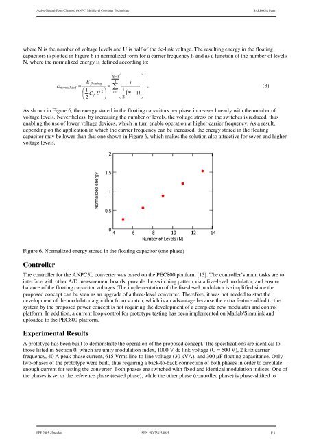
where N is the number of voltage levels and U is half of the dc-link voltage. The resulting energy in the floating<br />
capacitors is plotted in Figure 6 in normalized form for a carrier frequency fc and as a function of the number of levels<br />
N, where the normalized energy is defined according to:<br />
N −3<br />
2<br />
2<br />
E floating<br />
i<br />
E normalized =<br />
=<br />
. (3)<br />
1 2 1<br />
C<br />
i=<br />
1 ( N −1)<br />
f U<br />
2<br />
2<br />
As shown in Figure 6, the energy stored in the floating capacitors per phase increases linearly with the number of<br />
voltage levels. Nevertheless, by increasing the number of levels, the voltage stress on the switches is reduced, thus<br />
enabling the use of lower voltage devices, which in turn enable operation at higher carrier frequency. As a result,<br />
depending on the application in which the carrier frequency can be increased, the energy stored in the floating<br />
capacitor may be lower than that one shown in Figure 6, which makes the solution also attractive for seven and higher<br />
voltage levels.<br />
Figure 6. Normalized energy stored in the floating capacitor (one phase)<br />
Controller<br />
The controller for the <strong>ANPC</strong>5L converter was based on the PEC800 platform [13]. The controller’s main tasks are to<br />
interface with other A/D measurement boards, provide the switching pattern via a five-level modulator, and ensure<br />
balance of the floating capacitor voltages. The implementation of the five-level modulator is simplified since the<br />
proposed concept can be seen as an upgrade of a three-level converter. Therefore, it was not needed to start the<br />
development of the modulator algorithm from scratch, which is an advantage because the extra feature added to the<br />
system by the proposed power concept is not requiring the development of a complete new modulator and control<br />
platform. In addition, a current loop control for prototype testing has been implemented on Matlab/Simulink and<br />
uploaded to the PEC800 platform.<br />
Experimental Results<br />
A prototype has been built to demonstrate the operation of the proposed concept. The specifications are identical to<br />
those listed in Section 0, which are unity modulation index, 1000 V dc link voltage (U = 500 V), 2 kHz carrier<br />
frequency, 40 A peak phase current, 615 Vrms line-to-line voltage (30 kVA), and 300 µF floating capacitance. Only<br />
two-phases of the prototype were built, thus requiring a back-to-back connection of both phases in order to circulate<br />
enough current for testing the converter. Both phases are switched with fixed and identical modulation indices. One of<br />
the phases is set as the reference phase (tested phase), while the other phase (controlled phase) is phase-shifted to<br />
EPE 2005 - Dresden ISBN : 90-75815-08-5 P.8