Electrak: underfloor to workstation system guide - Legrand
Electrak: underfloor to workstation system guide - Legrand
Electrak: underfloor to workstation system guide - Legrand
- No tags were found...

You also want an ePaper? Increase the reach of your titles
YUMPU automatically turns print PDFs into web optimized ePapers that Google loves.
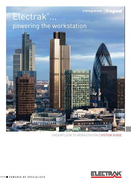
POWERINg THE WORKSTATIONUNDERFLOOR POWER<strong>Electrak</strong>’s power track <strong>system</strong> is perfect for supplying underloorpower in cavity loor installations. With minimal parts, push-itassembly and a complementary range of loor boxes, this lexible,easy <strong>to</strong> install <strong>system</strong> can be reconigured as ofice layouts evolve.POWER TRACKSee page 8CAVITY FLOOR BOXESSee page 22WORKSTATION POWER<strong>Electrak</strong>’s access grommets provide the gateway for power <strong>to</strong> feedfrom the underloor power track network <strong>to</strong> the <strong>workstation</strong>, whereall desk power requirements are met with our new range of deskmodules, Intersoc-R.GROMMETSSee page 30INTERSOC-RSee page 3405FULLY ADDRESSABLE LIGHTING CONTROLDesigned <strong>to</strong> work in harmony with <strong>Electrak</strong>’s buscom trunking,Lightrak’s lighting control <strong>system</strong> offers high end sophisticationwith unbeatable lexibility and speed of installation.Find out more at www.electrak.co.ukBUSCOMpower and data backboneLIGHTRAKlighting control <strong>system</strong>
<strong>Electrak</strong> ® ...UK manufacturing. global recognition30 YEARS OF EXPERIENCE<strong>Electrak</strong> has been designing and manufacturing costeffective <strong>system</strong>s that distribute power reliably and safelythroughout the workplace since the 1980s.As the inven<strong>to</strong>r of underloor busbar <strong>system</strong>s, <strong>Electrak</strong> setsthe benchmark for lexible power distribution.INDUSTRY EXPERTSAs part of its ongoing commitment <strong>to</strong> research anddevelopment, <strong>Electrak</strong> continually evolves its productranges <strong>to</strong> ensure it produces the best and most innovativesolutions available on the market.<strong>Electrak</strong> takes pride in its enviable reputation for marketleading cus<strong>to</strong>mer service, industry knowledge and productexpertise.QUALITY ASSURED UKMANUFACTURINGWith its UK manufacturing base situated in the North Eas<strong>to</strong>f England, <strong>Electrak</strong> adapts <strong>to</strong> the changing demands ofprojects by providing a rapid production process whilstensuring quality meets the highest standards.<strong>Electrak</strong>’s products are manufactured withinan ISO 9001 : 2008 facility and many carry theIntertek Diamondmark (where indicated).06
TRUSTED THROUGHOUT THE UK AND ACROSS THE WORLDUNITED KINGDOM• Morgan Stanley, Canary Wharf• Media City, Manchester• JP Morgan, Canary Wharf• RBS, Edinburgh• Bridgewater Place, Leeds• Network Rail, Nationwide• Swiss Re, City of London• Amazon, Swansea• Heathrow Airport, London• Morgan Stanley, Canary Wharf• Fort Dunlop, Birmingham• Royal Bank of Canada,City of London• Snow Hill, Birmingham• Barclays Capital, Canary Wharf• Temple Back, Bris<strong>to</strong>l• Standard Chartered Bank, City of London• London Underground• BBC, White City• Mann Island, LiverpoolMIDDLE EAST & INDIA• ADMA-OPCO HQ, Dubai• Internet City, Dubai• Burjuman Centre, Dubai• ADIC/Al Bahr Towers, Abu Dhabi• Al Dar HQ, Abu Dhabi• Central Bank of Kuwait• Ministry of Education, Kuwait• PIFFS Aridya, Kuwait• PAAET, Kuwait• Qatar News Agency• Barclays, Chennai, India• Barclays, Pune, India• Barclays, Andheri, India• Barclays, Mumbai, India• RBS, Delhi, India• Fidelity, Delhi, IndiaASIA PACIFIC• Credit Suisse, ICC I, Hong Kong• Deutsche Bank, ICC I, Hong Kong• Barclays Capital, CheungKong Centre• Cus<strong>to</strong>ms Headquarters,North Point, Hong Kong• Standard Chartered Bank,IFC II, Hong Kong• Citi Bank Tower, Hong Kong• Macquarie Bank, IFC I, Hong Kong• UBS Bank, IFC II, Hong Kong• JP Morgan, Hong Kong• Standard Chartered Bank, MarinaBay, Singapore• Barclays Capital, Marina Bay, Singapore• Nomura Bank, Marina Bay, Singapore• Credit Suisse, Serangoon Road,Singapore• ABN Amro, One Rafles Quay, Singapore• RBS, One George Street, Singapore• Barclays Capital, Shanghai• Standard Chartered Bank, Shanghai• UBS Bank, Shanghai07
08Power track...adaptable, reliable underloor power
THE INDUSTRY STANDARD IN UNDERFLOOR POWER<strong>Electrak</strong>’s power track <strong>system</strong> is perfect for cavity loor installations.With minimal parts, push-it assembly and a complementary range ofloor boxes and grommets, this lexible, easy <strong>to</strong> install <strong>system</strong> can bereconigured as ofice layouts evolve.Integral track connec<strong>to</strong>r plugs in<strong>to</strong> feed unit Lengths simply push-it <strong>to</strong>gether Integral ixing brackets for rapid installation Tap-offs plug in <strong>to</strong> shuttered socket outletsand lock on <strong>to</strong> track bodyThe <strong>system</strong> consists of continuous lengths of track which are fed via a feedunit and can be installed in loor voids as low as 48mm.• 63 A rated, IP 40 protection• Available in ive versions: single phase, clean earth, dual circuit, threephase and auxiliary earth• Available in 1.2m, 1.8m, 2.4m and 3.6m lengths• Tap-off outlets are located at every 300 or 600mm pitch• Floor mountable (stand-off brackets also available)09
<strong>Electrak</strong> ® power track <strong>system</strong>sDescriptionLength (m)Track lengths with 300 mm socket centres4 sockets6 sockets8 sockets12 sockets1·21·82·43·6Track feed–Excluding cables and conduit–Flexible metal conduit1·2Flexible metal conduit2·4Standard tap-off / auxiliary earth tap-offLow noise / clean earth tap-offDual circuit tap-off32 A unfused 16 mm Ø L, N, PE13 A fused 16 mm Ø L, N, PE13 A 543·7 fused 16 mm Ø L, N, PE32 A unfused 16 mm Ø CE, L, N, PE13 A fused 16 mm Ø CE, L, N, PE13 A 543·7 fused 16 mm Ø CE, L, N, PE35353535353532 A unfused 20 mm Ø CE, L1, N1 L2, N2, PE353 phase tap-off32 A 415 V 3 phase 20 mm Ø L1, L2, L3, N, PE32 A L1 unfused reconfigurable live pin 16 mm Ø L1, N, PE32 A L2 unfused reconfigurable live pin 16 mm Ø L2, N, PE32 A L3 unfused reconfigurable live pin 16 mm Ø L3, N, PE35353535Key code / Busbar arrangement10
ELECTRAK 24Standard <strong>system</strong>(white)ELECTRAK 25Low noise / clean earth<strong>system</strong> (green)ELECTRAK 26Dual circuit <strong>system</strong>(dark green)ELECTRAK 273 phase <strong>system</strong>(grey)ELECTRAK 28Auxiliary earth <strong>system</strong>(red)DA1123 JA2123 KA3123 NA4123 YA5123DA1183 JA2183 KA3183 NA4183 YA5183DA1243 JA2243 KA3243 NA4243 YA5243DA1363 JA2363 KA3363 NA4363 YA5363DF1010 JF2010 KF3010 NF4010 YF5010DW1000 JW2000 KW3000 NW4000 YW5000DW1010 JW2010 KW3010 NW4010 YW5010DW1020 JW2020 KW3020 NW4020 YW5020DP1332 – DP1332 – YP5332DP1532 – DP1532 – YP5532DP1313 – DP1313 – YP5313DP1513 – DP1513 – YP5513DP1327 – DP1327 – YP5327DP1527 – DP1527 – YP5527– JP2332 JP2332 – –– JP2532 JP2532 – –– JP2313 JP2313 – –– JP2513 JP2513 – –– JP2327 JP2327 – –– JP2527 JP2527 – –– – KP3328 – –– – KP3528 – –– – – NZ4331 –– – – NZ4531 –– – – NP4332 (1) –– – – NP4532 (1) –– – – NP4302 (1) –– – – NP4502 (1) –– – – NP4303 (1) –– – – NP4503 (1) –PE N2 L2 PE CE N1 L1 PE CE N1 L1 N2 L2 PE N L1 L2 L3 PE N1 L1(1) All NP tap-offs are reconfigurable between L1, L2 or L3 for 3 phase track11
<strong>Electrak</strong> ® 24 power track <strong>system</strong>standard <strong>system</strong> (white)DF1010DW1010- - -/- - -DA1123DP1332PackSelection chart (p. 10-11)Dimensions and technical information (p. 17-21)Approved <strong>to</strong> ASTA Standard 138 and ISO 9001 : 2008Conforms <strong>to</strong> BS EN 60439-2 : 2008. Fully complies with the requirements of BS 7671 : 2008 IEE Wiring RegulationsA compact <strong>system</strong> that can be installed in floor voids as low as 48 mmCat. Nos. Track <strong>system</strong> components<strong>Electrak</strong> 24 standard track lengthsTrack lengths fit <strong>to</strong>gether using the integralconnec<strong>to</strong>rs on each lengthTrack lengths should always be secured using theintegral floor fixing brackets300 mm socket centres1 DA1123 1·2 m, 4 sockets, 2 floor fixing brackets1 DA1183 1·8 m, 6 sockets, 2 floor fixing brackets1 DA1243 2·4 m, 8 sockets, 2 floor fixing brackets1 DA1363 3·6 m, 12 sockets, 3 floor fixing bracketsTrack feed unit1 DF1010 With one 25 mm diameter hole suitable for MICC,armoured cables or single core cables in conduitFlexible interlinksCan be used <strong>to</strong> overcome obstructions oras corners where required1 DW1000 Excluding cables and conduit1 DW1010 1·2 m flexible metal conduit1 DW1020 2·4 m flexible metal conduitSpecial fixing bracketsRequired when track is raised off surface levelBrackets raise track by 21 mm and should bespaced 600 mm apart1 DZ1210 For fitting under track body and track feed1 DZ1230 For fitting under integral track connec<strong>to</strong>rsPackCat. Nos. Tap-off unitsTap-off length is determined by the cable and notthe conduit length, e.g. a 3 m tap-off has 3 m ofcable and 2·6 m of flexible metal conduit (1)Tap-off units in excess of 3 m should only be used ifthey contain a fuse or if the power track is protectedby a protective device not exceeding 32 A32 A unfused16 mm Ø‚ L, N, PE1 DP1332 3 m1 DP1532 5 m13 A fused16 mm Ø‚ L, N, PE1 DP1313 3 m1 DP1513 5 m13 A 543·7 fused - high integrity16 mm Ø‚ L, N, PE1 DP1327 3 m1 DP1527 5 m(1) Tap-offs are supplied as standard with flexible metal conduitFor alternative wiring solutions, contact us on +44 (0) 845 600 626612
<strong>Electrak</strong> ® 25 power track <strong>system</strong>low noise / clean earth <strong>system</strong> (green)JF2010JW2010- - -/- - -JA2123JP2332PackSelection chart (p. 10-11)Dimensions and technical information (p. 17-21)Approved <strong>to</strong> ASTA Standard 138 and ISO 9001 : 2008Conforms <strong>to</strong> BS EN 60439-2 : 2008. Fully complies with the requirements of BS 7671 : 2008 IEE Wiring RegulationsA compact <strong>system</strong> that can be installed in floor voids as low as 48 mmCat. Nos. Track <strong>system</strong> components<strong>Electrak</strong> 25 low noise / clean earth track lengthsTrack lengths fit <strong>to</strong>gether using the integralconnec<strong>to</strong>rs on each lengthTrack lengths should always be secured using theintegral floor fixing brackets300 mm socket centres1 JA2123 1·2 m, 4 sockets, 2 floor fixing brackets1 JA2183 1·8 m, 6 sockets, 2 floor fixing brackets1 JA2243 2·4 m, 8 sockets, 2 floor fixing brackets1 JA2363 3·6 m, 12 sockets, 3 floor fixing bracketsTrack feed unit1 JF2010 With one 25 mm diameter hole suitable for MICC,armoured cables or single core cables in conduitFlexible interlinksCan be used <strong>to</strong> overcome obstructions oras corners where required1 JW2000 Excluding cables and conduit1 JW2010 1·2 m flexible metal conduit1 JW2020 2·4 m flexible metal conduitSpecial fixing bracketsRequired when track is raised off surface levelBrackets raise track by 21 mm and should bespaced 600 mm apart1 DZ1210 For fitting under track body and track feed1 DZ1230 For fitting under integral track connec<strong>to</strong>rsPackCat. Nos. Tap-off unitsTap-off length is determined by the cable and notthe conduit length, e.g. a 3 m tap-off has 3 m ofcable and 2·6 m of flexible metal conduit (1)Tap-off units in excess of 3 m should only be used ifthey contain a fuse or if the power track is protectedby a protective device not exceeding 32 A32 A unfused16 mm Ø‚ CE, L, N, PE1 JP2332 3 m1 JP2532 5 m13 A fused16 mm Ø‚ CE, L, N, PE1 JP2313 3 m1 JP2513 5 m13 A 543·7 fused - high integrity16 mm Ø‚ CE, L, N, PE1 JP2327 3 m1 JP2527 5 m(1) Tap-offs are supplied as standard with flexible metal conduitFor alternative wiring solutions, contact us on +44 (0) 845 600 626613
<strong>Electrak</strong> ® 26 power track <strong>system</strong>dual circuit <strong>system</strong> (dark green)KF3010KW3010- - -/- - -KA3123KP3328PackSelection chart (p. 10-11)Dimensions and technical information (p. 17-21)Approved <strong>to</strong> ASTA Standard 138 and ISO 9001 : 2008Conforms <strong>to</strong> BS EN 60439-2 : 2008. Fully complies with the requirements of BS 7671 : 2008 IEE Wiring RegulationsA compact <strong>system</strong> that can be installed in floor voids as low as 48 mmCat. Nos. Track <strong>system</strong> componentsThe dual power track <strong>system</strong> has both standard andlow noise / clean earth <strong>system</strong>s incorporated<strong>Electrak</strong> 26 dual circuit track lengthsTrack lengths fit <strong>to</strong>gether using the integralconnec<strong>to</strong>rs on each lengthTrack lengths should always be secured using theintegral floor fixing brackets300 mm socket centres1 KA3123 1·2 m, 4 sockets, 2 floor fixing brackets1 KA3183 1·8 m, 6 sockets, 2 floor fixing brackets1 KA3243 2·4 m, 8 sockets, 2 floor fixing brackets1 KA3363 3·6 m, 12 sockets, 3 floor fixing bracketsTrack feed unit1 KF3010 With two 25 mm diameter holes suitable for MICC,armoured cables or single core cables in conduitFlexible interlinksCan be used <strong>to</strong> overcome obstructions oras corners where required1 KW3000 Excluding cables and conduit1 KW3010 1·2 m flexible metal conduit1 KW3020 2·4 m flexible metal conduitSpecial fixing bracketsRequired when track is raised off surface levelBrackets raise track by 21 mm and should bespaced 600 mm apart1 DZ1210 For fitting under track body and track feed1 DZ1230 For fitting under integral track connec<strong>to</strong>rsPackCat. Nos. Tap-off unitsTap-off length is determined by the cable and notthe conduit length, e.g. a 3 m tap-off has 3 m ofcable and 2·6 m of flexible metal conduit (1)Tap-off units in excess of 3 m should only be used ifthey contain a fuse or if the power track is protectedby a protective device not exceeding 32 AStandard 32 A unfused16 mm Ø‚ L, N, PE1 DP1332 3 m1 DP1532 5 mStandard 13 A fused16 mm Ø‚ L, N, PE1 DP1313 3 m1 DP1513 5 mStandard 13 A 543·7 fused16 mm Ø‚ L, N, PE1 DP1327 3 m1 DP1527 5 mLow noise / clean earth 32 A unfused16 mm Ø‚ CE, L, N, PE1 JP2332 3 m1 JP2532 5 mLow noise / clean earth 13 A fused16 mm Ø‚ CE, L, N, PE1 JP2313 3 m1 JP2513 5 mLow noise / clean earth 13 A 543·7 fused16 mm Ø‚ CE, L, N, PE1 JP2327 3 m1 JP2527 5 mDual circuit 32 A unfused20 mm Ø‚ CE, L1, N1, L2, N2,PE1 KP3328 3 m1 KP3528 5 m(1) Tap-offs are supplied as standard with flexible metal conduitFor alternative wiring solutions, contact us on +44 (0) 845 600 626614
<strong>Electrak</strong> ® 27 power track <strong>system</strong>3 phase <strong>system</strong> (grey)NF4010NW4010- - -/- - -NA4123NZ4331Selection chart (p. 10-11)Dimensions and technical information (p. 17-21)Approved <strong>to</strong> ASTA Standard 138 and ISO 9001 : 2008Conforms <strong>to</strong> BS EN 60439-2 : 2008. Fully complies with the requirements of BS 7671 : 2008 IEE Wiring RegulationsA compact <strong>system</strong> that can be installed in floor voids as low as 48 mmPack Cat. Nos. Track <strong>system</strong> components<strong>Electrak</strong> 27 3 phase track lengthsTrack lengths fit <strong>to</strong>gether using the integralconnec<strong>to</strong>rs on each lengthTrack lengths should always be secured using theintegral floor fixing brackets300 mm socket centres1 NA4123 1·2 m, 4 sockets, 2 floor fixing brackets1 NA4183 1·8 m, 6 sockets, 2 floor fixing brackets1 NA4243 2·4 m, 8 sockets, 2 floor fixing brackets1 NA4363 3·6 m, 12 sockets, 3 floor fixing bracketsTrack feed unit1 NF4010 With one 25 mm diameter hole suitable for MICC,armoured cables or single core cables in conduitFlexible interlinksCan be used <strong>to</strong> overcome obstructions oras corners where required1 NW4000 Excluding cables and conduit1 NW4010 1·2 m flexible metal conduit1 NW4020 2·4 m flexible metal conduitSpecial fixing bracketsRequired when track is raised off surface levelBrackets raise track by 21 mm and should bespaced 600 mm apart1 DZ1210 For fitting under track body and track feed1 DZ1230 For fitting under integral track connec<strong>to</strong>rsPack Cat. Nos. Tap-off unitsTap-off length is determined by the cable and notthe conduit length, e.g. a 3 m tap-off has 3 m ofcable and 2·6 m of flexible metal conduit (1)Tap-off units in excess of 3 m should only be used ifthey contain a fuse or if the power track is protectedby a protective device not exceeding 32 A32 A 415 V 3 phase20 mm Ø‚ L1, L2, L3, N, PE1 NZ4331 3 m1 NZ4531 5 m32 A L1 (2) unfusedUnfusedReconfigurable live pin16 mm Ø‚ L, N, PE1 NP4332 3 m1 NP4532 5 m32 A L2 (2) unfusedUnfusedReconfigurable live pin16 mm Ø‚ L, N, PE1 NP4302 3 m1 NP4502 5 m32 A L3 (2) unfusedUnfusedReconfigurable live pin16 mm Ø‚ L, N, PE1 NP4303 3 m1 NP4503 5 m(1) Tap-offs are supplied as standard with flexible metal conduitFor alternative wiring solutions, contact us on +44 (0) 845 600 6266(2) All NP tap-offs are reconfigurable between L1, L2, or L3 for3 phase track15
<strong>Electrak</strong> ® 28 power track <strong>system</strong>auxiliary earth <strong>system</strong> (red)YF5010YW5010- - -/- - -YA5123YP5332PackSelection chart (p. 10-11)Dimensions and technical information (p. 17-21)Approved <strong>to</strong> ASTA Standard 138 and ISO 9001 : 2008Conforms <strong>to</strong> BS EN 60439-2 : 2008. Fully complies with the requirements of BS 7671 : 2008 IEE Wiring RegulationsA compact <strong>system</strong> that can be installed in floor voids as low as 48 mmCat. Nos. Track <strong>system</strong> components<strong>Electrak</strong> 28 auxiliary earth track lengthsTrack lengths fit <strong>to</strong>gether using the integralconnec<strong>to</strong>rs on each lengthTrack lengths should always be secured using theintegral floor fixing brackets300 mm socket centres1 YA5123 1·2 m, 4 sockets, 2 floor fixing brackets1 YA5183 1·8 m, 6 sockets, 2 floor fixing brackets1 YA5243 2·4 m, 8 sockets, 2 floor fixing brackets1 YA5363 3·6 m, 12 sockets, 3 floor fixing bracketsTrack feed unit1 YF5010 With one 25 mm diameter hole suitable for MICC,armoured cables or single core cables in conduitFlexible interlinksCan be used <strong>to</strong> overcome obstructions oras corners where required1 YW5000 Excluding cables and conduit1 YW5010 1·2 m flexible metal conduit1 YW5020 2·4 m flexible metal conduitSpecial fixing bracketsRequired when track is raised off surface levelBrackets raise track by 21 mm and should bespaced 600 mm apart1 DZ1210 For fitting under track body and track feed1 DZ1230 For fitting under integral track connec<strong>to</strong>rsPackCat. Nos. Tap-off unitsTap-off length is determined by the cable and notthe conduit length, e.g. a 3 m tap-off has 3 m ofcable and 2·6 m of flexible metal conduit (1)Tap-off units in excess of 3 m should only be used ifthey contain a fuse or if the power track is protectedby a protective device not exceeding 32 A32 A unfused16 mm Ø‚ L, N, PE1 YP5332 3 m1 YP5532 5 m13 A fused16 mm Ø‚ L, N, PE1 YP5313 3 m1 YP5513 5 m13 A 543·7 fused - high integrity16 mm Ø‚ L, N, PE1 YP5327 3 m1 YP5527 5 m(1) Tap-offs are supplied as standard with flexible metal conduitFor alternative wiring solutions, contact us on +44 (0) 845 600 626616
<strong>Electrak</strong> ® power track <strong>system</strong>sdesign and installationn General installation notes<strong>Electrak</strong> power track is a compact <strong>system</strong> that can be installed in floorvoids as low as 48 mmTrack feed boxes are provided with one or two 25 mm diameter holessuitable for MICC, armoured cables or single core cables in conduitTrack lengths connect <strong>to</strong>gether and <strong>to</strong> track feeds using the integralconnec<strong>to</strong>rs on each lengthTrack lengths should always be secured using the integral floor fixingbrackets ; three on the 3·6 m length and two on 2·4 m, 1·8 m or 1·2 mlengthsn Special fixing bracketsWhen installing track off-floor, <strong>Electrak</strong> special fixing brackets raisetrack by 21 mm. Ensure brackets are spaced 600 mm apart andalways have support under the integral track connec<strong>to</strong>r and track feed.Failure <strong>to</strong> do so may undermine the integrity of the <strong>system</strong>Cat. No. DZ1210 raised off-floor fixing brackets are spaced at 600 mmcentres along track. Also use bot<strong>to</strong>m half of bracket under track feedand flexible interlinkCat. No. DZ1230 raised off-floor fixing brackets are always used underintegral track connec<strong>to</strong>rs. Track is secured <strong>to</strong> raised brackets using thetrack’s integral fixing bracketAccess <strong>to</strong> power is provided along the track length by simply pluggingtap-off units in<strong>to</strong> shuttered socket outlets. These tap-off units feed alltypes of conventional floor service outlet boxes or feed <strong>workstation</strong>sdirectly through the floor via 4 mm 2 or 1·5 mm 2 insulated conduc<strong>to</strong>rscontained in flexible metal or VO rated nylon conduit. When connectingtap-offs directly through the floor via grommet outlets <strong>to</strong> <strong>workstation</strong>scare must be taken <strong>to</strong> ensure that the tap-off length is adequateThe dual power track <strong>system</strong> has both standard and low noise / cleanearth <strong>system</strong>s incorporated. As well as dual tap-offs, both standardand low noise / clean earth tap-offs can be plugged in<strong>to</strong> any socke<strong>to</strong>utlet along the track length. The dual tap-off incorporates bothstandard and low noise cables50 mm7 mm ØIntegral track connec<strong>to</strong>rIntegral track fixing bracketscrews <strong>to</strong> special bracket185 mm7 mm ØOptimum layout flexibility is achieved by positioning track lengths amaximum of 5·2 m apart and 2·5 m from the wall, and by connectingthe 3 m tap-off units <strong>to</strong> floor outlet boxes. This means every part of thefloor area can be served. Flexible interlinks can be used <strong>to</strong> overcomeobstructions or used as corners if required99 mmCat. No. DZ121021 mm <strong>to</strong> underside of track36 mm <strong>to</strong> <strong>to</strong>p of trackCat. No. DZ1230n Dimensions93752501091186846464732152 x 25 Ø25 Ø65End view AEnd view B92Integral fixingbracket fixingcentresExample floor layout2·5 m5·2 msocket outlet points every300 or 600 mm alongtrack length5·2 m3 m flexibletap-off unitfloor serviceoutlet boxtrack feed5·2 mintegral trackconnec<strong>to</strong>rsAll dimensions (mm) are nominal17
<strong>Electrak</strong> ® power track <strong>system</strong>sdesign and installation (continued)n Product configurationFlexible interlinkTap-off connectionTrack and flexible interlinkboxes must be securelyfixed inline <strong>to</strong> surface sono movement can takeplace after fixingDepress tap-off side clips and push downTap-offPush downSide clipRemove dust coverfrom power trackend entry socketbefore useInterlink feedentry socket.Remove dustcover labelPower trackMake sure both tapoffside clips are fullypushed home on bothsides of trackScrew fix <strong>to</strong> surfaceTrack feed (Cat. No. DF1010) Sub-cablingTap-off connectionTrack feed protective earthterminal and earth bondTap-off metalflexible conduitConnec<strong>to</strong>r terminalsProtective earth mustalways be connected viathe earth terminal blockLift lid20 mm Ø conduit fitting.Tighten back nut securelyLift terminal tab <strong>to</strong> accessterminal screws and closeafter use25 mm Ø cableconduit fixing holeClose lid and secure with lidfixing screw before power upTrack feed (Cat. No. JF2010) Sub-cablingTrack feed protective earthterminal and earth bondTap-off connectionTap-off metalflexible conduitConnec<strong>to</strong>r terminalsProtective earth mustalways be connected viathe earth terminal blockLift lid20 mm Ø conduit fittingTighten back nut securelyLift terminal tab <strong>to</strong> accessterminal screws and closeafter useClean earth25 mm Ø cableconduit fixing holeClose lid and secure with lidfixing screw before power up18
Track feed (Cat. No. KF3010) Sub-cablingLift terminal tab <strong>to</strong> accessterminal screws and closeafter useDual tap-off connection (dark green)Tap-off metalflexible conduitProtective earthmust always beconnected via theearth terminal blockTrack feed protectiveearth terminal andearth bondLift lid20 mm Ø conduit fittingTighten back nut securelyConnectionsL1, N1, CE = low noiseL2, N2, PE = standardConnectionsL1, N1, CE = low noiseL2, N2, PE = standard Connec<strong>to</strong>r terminalsClean earth2 x 25 mm Øcable conduitfixing holeClose lid and secure with lidfixing screw before power upTrack feed (Cat. No. NF4010) Sub-cablingTrack feed protective earthterminal and earth bond3 phase tap-off connectionTap-off metalflexible conduitProtective earth mustalways be connected viathe earth terminal blockLift lid20 mm Ø conduit fittingTighten back nut securelyConnec<strong>to</strong>r terminalsLift terminal tab <strong>to</strong> accessterminal screws and closeafter use25 mm Ø cableconduit fixing holeClose lid and secure with lidfixing screw before power upTrack feed (Cat. No. YF5010) Sub-cablingTrack feed protective earthterminal and earth bondTap-off connectionTap-off metalflexible conduitConnec<strong>to</strong>r terminalsProtective earth mustalways be connected viathe earth terminal blockLift lid20 mm Ø conduit fittingTighten back nut securelyLift terminal tab <strong>to</strong> accessterminal screws and closeafter use25 mm Ø cableconduit fixing holeClose lid and secure with lidfixing screw before power up19
<strong>Electrak</strong> ® power track <strong>system</strong>sinstallation1 Fix track feed <strong>to</strong> surfaceTrack feedDirection oftrack runMake chalk line <strong>to</strong>align track lengths2 Connect track length <strong>to</strong> track feedRemovedust coverIntegral trackconnec<strong>to</strong>rTrack lengthPush downTrack feedMake sure trackconnec<strong>to</strong>r clips arefully pushed home onboth sides of trackPush downPower track andintegral trackconnec<strong>to</strong>r3 Connect additional track lengthsRemove dust coverbefore connectingtrack connec<strong>to</strong>rFirst trackfixing bracketTrack outletsreusable plasticdust covers4 Secure track lengths <strong>to</strong> surfacePull out track fixingbracket lugs and screwfix on both sidesAll integral track fixing bracketsmust be fixed <strong>to</strong> surface at 1·2 mfixing centres from first bracke<strong>to</strong>n each track length20
<strong>Electrak</strong> ® power track <strong>system</strong>stechnical datan StandardsApproved <strong>to</strong> ASTA Standard 138BS EN 60439-2 : 2000, BS EN 61534-22 : 2009 and IEC 61534-22 : 2009Manufactured within an approved ISO 9001 : 2008 facilityAssessed Quality Assurance Certificate No. 2029<strong>Electrak</strong> fully complies with the requirements of BS 7671 : 2008 + A1 : 2011(IET Wiring Regulations)n Earth fault loop impedanceBS 7671 : 2008 + A1 : 2011 IET Wiring Regulations require accuratedetermination of the <strong>to</strong>tal earth loop impedance, which must besufficiently low <strong>to</strong> allow the protective device <strong>to</strong> operate within thespecified time, which for socket outlets is 0·4 seconds. The valuesrelevant <strong>to</strong> <strong>Electrak</strong> for calculating the earth fault loop impedance areshown in the electrical test data table, see oppositen Durability<strong>Electrak</strong> <strong>system</strong>s are superbly designed and extremely robust. Theycan be expected <strong>to</strong> stand up <strong>to</strong> all normal site conditions. <strong>Electrak</strong> hasbeen short circuit strength tested by ASTAn Installations with high protective conduc<strong>to</strong>r currentsAll unfused tap-offs comply with Regulation 543·7 without the need foradditional earth conduc<strong>to</strong>rs. Regulation 543·7·1·103 (ii) states “a singlecopper protective conduc<strong>to</strong>r having a cross-sectional area of not lessthan 4 mm 2 , complying with the requirements of Regulations 543·2 and543·3, the protective conduc<strong>to</strong>r being enclosed <strong>to</strong> provide additionalprotection against mechanical damage, for example, within a flexibleconduit”For installations with high protective conduc<strong>to</strong>r currents requiringfused tap-offs, a 543·7 compliant tap-off must be used. Normallyfused tap-offs incorporate 1·5 mm 2 conduc<strong>to</strong>rs, however in the fused543·7 tap-offs, the 1·5 mm 2 earth conduc<strong>to</strong>r is replaced with a 4 mm 2conduc<strong>to</strong>r and therefore complies with Section 543·7·1·103 (ii)n 32 A tap-off unitThe 3 m 32 A tap-off unit comprises an unfused tap-off with either2·6 m of 16 mm / 20 mm diameter flexible metal conduit or VO ratednylon conduit both with integral 4 mm 2 LSOH conduc<strong>to</strong>rsThese units are designed <strong>to</strong> comply with regulation 434·2·1 of theIET Wiring Regulations by virtue of the following :• maximum length of cable is 3 m• it is fac<strong>to</strong>ry assembled and fully tested item with cable installed in highquality flexible conduitFault condition protection for the tap-off assembly and the floor boxsocket outlets is delivered by the circuit protection deviceDisconnection time for socket outlets is 0·4 seconds (Regulation411·3·2·2). The <strong>Electrak</strong> <strong>system</strong> meets this requirementTap-off units in excess of 3 m should only be used if they contain a fuseor the power track is protected by a protective device not exceeding 32 AVolt drops (live and neutral)Busbars3·0 mV/A/mCable connec<strong>to</strong>r0·4 mV/ATrack connec<strong>to</strong>r0·4 mV/A32 A tap-off 0·4 mV/A+ 4 mm 2 cable 11 mV/A/mFlexible corner assembly1·5 mV/A+ 10 mm 2 cable 4·0 mV/A/mMechanical dataNumber of conduc<strong>to</strong>rs 3 <strong>to</strong> 6Busbar conduc<strong>to</strong>r cross sectional area 13 mm 2Housing cross sectional area (copper equivalent) 13 mm 2Cable terminal capacity 16 mm 2Tap-off cable 32 A 4 mm 2Tap-off cable 13 A fused 1·5 mm 2Tap-off conduit, up <strong>to</strong> 4 conduc<strong>to</strong>rs16 mmØTap-off conduit, 5 and 6 conduc<strong>to</strong>rs20 mmØFlexible corner cable (tri-rated, high temperature) 10 mm 2Flexible corner conduit25 mmØIP rating 40Earth fault loop impedancePhase busbar1·5 mΩ/mEarth busbar1·5 mΩ/mEarth housing1·1 mΩ/mEarth busbar and housing0·8 mΩ/mCable connec<strong>to</strong>r0·4 mΩTrack connec<strong>to</strong>r0·6 mΩ32 A tap-off 0·6 mΩ+ 4 mm 2 cable 11 mΩ/mFlexible corner assembly1·5 mΩ+ 10 mm 2 cable 4·0 mΩ/mRated conditional short-circuit current16 KAAmbient temperature25˚CElectrical test dataRated current63 ARated voltage 230/400 V~Frequency50/60 HzConduc<strong>to</strong>r resistance - live and neutral 3·0 mΩ/mConduc<strong>to</strong>r impedance1·5 mΩ/mMaterial specificationsPower track housingGalvanised steel, natural finishBusbarsHigh conductivity copperBusbar insula<strong>to</strong>rPTFETrack connec<strong>to</strong>r/socket outlet/track feed connec<strong>to</strong>r Flame retardant polycarbonateSocket outlet entry shutterAcetalTap-off housingFlame retardant polycarbonateTrack connec<strong>to</strong>r bladesCopperTap-off bladesCopperTap-off/flexible corner conduit, metalElectro-galvanised steelTap-off conduit, plasticVO ratedTap-off cable LSOH <strong>to</strong> BS 7211Flexible interlink cable Tri-rated <strong>to</strong> BS 6231Track feed box/flexible interlink boxesGalvanised steelTrack feed connec<strong>to</strong>r terminals/earth block BrassTrack fixing bracketsGalvanised steel13 A tap-off, fuse To BS 1362, ASTA approved21
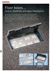
Floor boxes...choice, lexibility and easy installation<strong>Electrak</strong>’s 2, 3 and 4 compartment raised access loor boxes and slab boxesoffer complete versatility. Floor boxes are available pre-wired with power tracktap-off, or supplied empty (unassembled), with a choice of single or separatecompartment bases and three depth options. With a vast selection of power anddata plates available, boxes can be tailored <strong>to</strong> the speciic requirements of eachofice installation.22
Rapid it /remove mechanismadjusts for looring thicknessQuick-it, reversible lid forrapid installationDurable ABS trim andlid surroundVarious RCD protectionoptions availableRapid it push lock securesbase in loor apertureAvailable pre-wired withtap-offThree depth options:75mm, 85mm, 110mmSingle or separatecompartment bases23Available in 2, 3 and 4 compartments and with a choice ofthree depths, <strong>Electrak</strong>’s loor boxes have been developedwith a host of special features:• Available pre-wired with tap-off or supplied unassembled• A vast selection of power and data plates,including RCD options• Single or separate compartment bases for ease of datacabling• Rapid installation and fast ratchet mechanism whichadjusts <strong>to</strong> loor inish thickness
access floor service outlet and slab mounted floor boxesempty boxes and accessory plates2 compartment3 compartment4 compartmentTo configure boxes as required, select :1. Box depth2. Number of compartments required3. Desired accessory plates230 mm290 mm230 mm366 mm230 mm366 mmEmpty boxesExample100 mmwidth plates100 mmwidth plates75 mmwidth platesSingle base – 75 mm depthCR2001 CR011 CR4001Single base – 85 mm depth (standard box)CR2002 CR012 CR4002Single base – 110 mm depthCR2003 CR013 CR4003Separate compartment base – 75 mm depthCR2004 CR014 CR4004Separate compartment base – 85 mm depthCR2005 CR015 CR4005Separate compartment base – 110 mm depthCR2006 CR016 CR4006Slab boxes 1 compartment 2 compartment 3 compartment 4 compartmentFix directly on<strong>to</strong> floor slab (supplied empty)CR5102 CR5202 CR5302 CR5402Accessory plates For 1, 2 and 3 compartment boxes For 4 compartment boxesBlank plateCR020CR41002 gang switched socket outlet2 gang switched socket outlet,low noise / clean earthCR022CR023CR4101CR41022 gang non-standard switched socket outletCR027CR41032 gang unswitched socket outletCR029CR41043 gang unswitched socket outletCR030CR41053 gang unswitched socket outlet,low noise / clean earth2 gang RCD socket outletCR044CR036CR4118CR41112 gang RCD socket outlet,low noise / clean earthCR043CR4117Punched plate for 2 x 1 gang accessories(60·3 mm fixing centres)Punched plate for 2 gang accessories(120·6 mm fixing centres)CR026 –CR028 –Angled punched plate for 4 x RJ45 sockets(37 mm x 22 mm cut-outs)2 x LJ2 accessory plate (50 mm fixing centres)CR042CR031CR4115CR41064 x BNC connec<strong>to</strong>r plateCR033CR41084 x Data / telecoms plate(37 mm x 22 mm cut-outs)6 x Data / telecoms plate(37 mm x 22 mm cut-outs)CR024CR025CR4112CR411324
access floor pre-wired service outlet boxesand accessory platesPre-wired service outlet boxes with <strong>Electrak</strong> tap-offs1. Select power track tap-off and desired configuration2. Select additional accessory plates (if required)3 compartmentIncludes 1 x twinswitched socket outletIncludes 2 x twinswitched socket outletIncludes 1 x 2 gangRCD socket outletIncludes 2 x 2 gangRCD socket outlet<strong>Electrak</strong> 24 - standard tap-off<strong>Electrak</strong> 25 - low noise /clean earth tap-offDP1332 - 3 m CR100 CR102 CR100R CR102RDP1532 - 5 m CR101 CR103 CR101R CR103R230 mm366 mmJP2332 - 3 m CR110 CR112 CR110R CR112RJP2532 - 5 m CR111 CR113 CR111R CR113R<strong>Electrak</strong> 28 - auxiliary earth tap-offYP5332 - 3 m CR104 CR106 CR104R CR106RYP5532 - 5 m CR105 CR107 CR105R CR107RAdditional plates for 3 compartment boxesBlank plateCR0202 x LJ2 accessory plate(50 mm fixing centres)CR031Punched plate for 2 x 1 gang accessories(60·3 mm fixing centres)CR0264 x BNC connec<strong>to</strong>r plateCR033Punched plate for 2 gang accessories(120·6 mm fixing centres)CR0284 x Data / telecoms plate(37 mm x 22 mm cut-outs)CR024Angled punched plate for 4 xRJ45 sockets (37 mm x 22 mm cut-outs)CR0426 x Data / telecoms plate(37 mm x 22 mm cut-outs)CR0254 compartmentIncludes 1 x twinswitched socke<strong>to</strong>utletIncludes 2 x twinswitched socke<strong>to</strong>utletIncludes 1 x 2 gangRCD socket outletIncludes 2 x 2 gangRCD socket outletModular RCDprotecting 2 x twinswitched socke<strong>to</strong>utlets and 1 sparecompartment<strong>Electrak</strong> 24 - standard tap-off<strong>Electrak</strong> 25 - low noise /clean earth tap-offDP1332 - 3 m CR120 CR122 CR120R CR122R CR4402DP1532 - 5 m CR121 CR123 CR121R CR123R CR4403JP2332 - 3 m CR130 CR132 CR130R CR132R CR4412230 mm366 mm<strong>Electrak</strong> 28 - auxiliary earth tap-offJP2532 - 5 m CR131 CR133 CR131R CR133R CR4413Additional plates for 4 compartment boxesYP5332 - 3 m CR124 CR126 CR124R CR126R CR4406YP5532 - 5 m CR125 CR127 CR125R CR127R CR4407Blank plateCR41004 x BNC connec<strong>to</strong>r plateCR4108Angled punched plate for 4 xRJ45 sockets (37 mm x 22 mm cut-outs)CR41154 x Data / telecoms plate(37 mm x 22 mm cut-outs)CR41122 x LJ2 accessory plate(50 mm fixing centres)CR41066 x Data / telecoms plate(37 mm x 22 mm cut-outs)CR411325
access floor service outlet boxesempty boxesslab mounted floor boxesempty boxesCR5302CR4002CR0123 compartment slab floor box shown with two twinswitched socket outlets, punched data plate and apower track tap-offCR5102Selection chart (p. 24)Dimensions and technical information (p. 29)Lid and trim mouldings are precision engineered from hard wearingdurable ABS. The lid is reinforced with a galvanised mild steel plateMounting frame and box base - 0·9 mm thick galvanised steelEach compartment has 2 entries for 20 mm and 2 entries for 25 mmflexible conduitsGrey mouldings. Alternative colours available <strong>to</strong> special order. Goosewinggrey plates2, 3 and 4 compartment boxes are also available with separate individualcompartment base units for convenient offsite pre-wiringSupplied in parts or fully assembled and configured <strong>to</strong> cus<strong>to</strong>merspecificationConform <strong>to</strong> IEC-61534-22<strong>Electrak</strong> slab floor boxes are an ideal solution for <strong>underfloor</strong> power anddata requirementsUsed in conjunction with <strong>Electrak</strong> floor grommets, slab boxes preventunwanted access <strong>to</strong> power and data connectionsPackCat. Nos. 2 compartment floor boxesEmpty boxes100 mm compartment widths1 CR2001 Single base - 75 mm depth1 CR2002 Single base - 85 mm depth (standard box)1 CR2003 Single base - 110 mm depth1 CR2004 Separate compartment base - 75 mm depth1 CR2005 Separate compartment base - 85 mm depth1 CR2006 Separate compartment base - 110 mm depth3 compartment floor boxesEmpty boxes100 mm compartment widths1 CR011 Single base - 75 mm depth1 CR012 Single base - 85 mm depth (standard box)1 CR013 Single base - 110 mm depth1 CR014 Separate compartment base - 75 mm depth1 CR015 Separate compartment base - 85 mm depth1 CR016 Separate compartment base - 110 mm depthPackCat. Nos. Slab floor boxesFixes directly on<strong>to</strong> floor slabFast and efficient installation with integrated fixingplatesWide range of power and data accessory platesManufactured from 0·9 mm thick galvanised steelEach compartment has 2 entries for 20 mm and2 entries for 25 mm flexible conduits100 mm compartment widthsUse plates from the 1, 2 and 3 compartment floor boxsection (p. 24)1 CR5102 1 compartment slab floor box1 CR5202 2 compartment slab floor box1 CR5302 3 compartment slab floor box75 mm compartment widthsUse plates from the 4 compartment floor box section(p. 24)1 CR5402 4 compartment slab floor box4 compartment floor boxesEmpty boxes75 mm compartment widths1 CR4001 Single base - 75 mm depth1 CR4002 Single base - 85 mm depth (standard box)1 CR4003 Single base - 110 mm depth1 CR4004 Separate compartment base - 75 mm depth1 CR4005 Separate compartment base - 85 mm depth1 CR4006 Separate compartment base - 110 mm depthScreed / edge trim boxes, and metal orlockable lids are available <strong>to</strong> ordercontact us on +44 (0) 845 600 626626
access floor service outlet boxesaccessory plates and ancillary itemsSelection chart (p. 24-25)Dimensions and technical information (p. 29)Lid and trim mouldings are precision engineered from hard wearing durable ABS. Lid is reinforced with a galvanised mild steel plateMounting frame and box base - 0·9 mm thick galvanised steelEach compartment has 2 entries for 20 mm and 2 entries for 25 mm flexible conduitsGrey mouldings. Alternative colours available <strong>to</strong> special order. Goosewing grey plates2, 3 and 4 compartment boxes are also available with separate individual compartment base units for convenient offsite pre-wiringSupplied in parts or fully assembled and configured <strong>to</strong> cus<strong>to</strong>mer specificationConform <strong>to</strong> IEC-61534-22PackCat. Nos. 1, 2 and 3 compartment accessory plates100 mm width1 CR020 Blank plate1 CR022 2 gang switched socket outlet1 CR023 2 gang switched socket outlet, low noise / clean earth1 CR027 2 gang non-standard switched socket outlet1 CR029 2 gang unswitched socket outlet1 CR030 3 gang unswitched socket outletCR044 3 gang unswitched socket outlet,low noise / clean earth1 CR036 2 gang RCD socket outlet1 CR043 2 gang RCD socket outlet, low noise / clean earth1 CR026 Punched plate for 2 x 1 gang accessories(60·3 mm fixing centres)1 CR028 Punched plate for 2 gang accessories(120·6 mm fixing centres)1 CR042 Angled punched plate for 4 x RJ45(37 mm x 22 mm cut-outs)1 CR031 2 x LJ2 accessory plate (50 mm fixing centres)1 CR033 4 x BNC connec<strong>to</strong>r plate1 CR024 4 x Data / telecoms plate (37 mm x 22 mm cut-outs)1 CR025 6 x Data / telecoms plate (37 mm x 22 mm cut-outs)PackCat. Nos. 4 compartment accessory plates75 mm compartment widths1 CR4100 Blank plate1 CR4101 2 gang switched socket outlet1 CR4102 2 gang switched socket outlet, low noise / clean earth1 CR4103 2 gang non-standard switched socket outlet1 CR4104 2 gang unswitched socket outlet1 CR4105 3 gang unswitched socket outletCR4118 3 gang unswitched socket outlet,low noise / clean earth1 CR4111 2 gang RCD socket outlet1 CR4117 2 gang RCD socket outlet, low noise / clean earth1 CR4115 Angled punched plate for 4 x RJ45(37 mm x 22 mm cut-outs)1 CR4106 2 x LJ2 accessory plate (50 mm fixing centres)1 CR4108 4 x BNC connec<strong>to</strong>r plate1 CR4112 4 x Data / telecoms plate (37 mm x 22 mm cut-outs)1 CR4113 6 x Data / telecoms plate (37 mm x 22 mm cut-outs)Ancillary items for service outlet boxes1 CR0001 Floor tile cut-out template – 2 compartment1 CR0003 Floor tile cut-out template – 3/4 compartment10 CR0000 Cable outlet flap10 CR0010 Cable routers50 CR0011 Screws for accessory plates1 CR0012 Pack of 5 keys for use with lockable floor boxes1 CR0002 Lid – 2 compartment box1 CR0004 Lid – 3/4 compartment box1 CR0005 Mounting frame for vinyl floor. For 2 compartment boxReplaces mounting frame attached <strong>to</strong> base1 CR0006 Mounting frame for vinyl floor. For 3/4 compartmentbox. Replaces mounting frame attached <strong>to</strong> base10 CR0007 Floor box lid handle1 CR0020 Metal lid and trim - replacement for 3 and 4compartment boxes - powder coated grey<strong>Electrak</strong> tap-offs (see p. 12-16)27
access floor pre-wired service outlet boxes3 and 4 compartmentCR100CR122Dimensions and technical information (p. 29)<strong>Electrak</strong> floor boxes can be supplied pre-wired <strong>to</strong> power track tap-offs with any variation of sockets, tap-offs, depth or other configurationPackCat. Nos. 3 compartment pre-wired boxes with 1 x TSSO100 mm compartment widthsSingle base – 85 mm depth, pre-wired with :1 CR100 3 m <strong>Electrak</strong> 24 standard tap-off Cat. No. DP13321 CR101 5 m <strong>Electrak</strong> 24 standard tap-off Cat. No. DP15321 CR110 3 m <strong>Electrak</strong> 25 low noise / clean earth tap-offCat. No. JP23321 CR111 5 m <strong>Electrak</strong> 25 low noise / clean earth tap-offCat. No. JP25321 CR104 3 m <strong>Electrak</strong> 28 auxiliary earth tap-offCat. No. YP53321 CR105 5 m <strong>Electrak</strong> 28 auxiliary earth tap-offCat. No. YP55323 compartment pre-wired boxes with 2 x TSSO100 mm compartment widthsSingle base – 85 mm depth, pre-wired with :1 CR102 3 m <strong>Electrak</strong> 24 standard tap-off Cat. No. DP13321 CR103 5 m <strong>Electrak</strong> 24 standard tap-off Cat. No. DP15321 CR112 3 m <strong>Electrak</strong> 25 low noise / clean earth tap-offCat. No. JP23321 CR113 5 m <strong>Electrak</strong> 25 low noise / clean earth tap-offCat. No. JP25321 CR106 3 m <strong>Electrak</strong> 28 auxiliary earth tap-offCat. No. YP53321 CR107 5 m <strong>Electrak</strong> 28 auxiliary earth tap-offCat. No. YP5532PackCat. Nos. 4 compartment pre-wired boxes with 1 x TSSO75 mm compartment widthsSingle base – 85 mm depth, pre-wired with :1 CR120 3 m <strong>Electrak</strong> 24 standard tap-off Cat. No. DP13321 CR121 5 m <strong>Electrak</strong> 24 standard tap-off Cat. No. DP15321 CR130 3 m <strong>Electrak</strong> 25 low noise / clean earth tap-offCat. No. JP23321 CR131 5 m <strong>Electrak</strong> 25 low noise / clean earth tap-offCat. No. JP25321 CR124 3 m <strong>Electrak</strong> 28 auxiliary earth tap-off Cat. No. YP53321 CR125 5 m <strong>Electrak</strong> 28 auxiliary earth tap-off Cat. No. YP55324 compartment pre-wired boxes with 2 x TSSO75 mm compartment widthsSingle base – 85 mm depth, pre-wired with :1 CR122 3 m <strong>Electrak</strong> 24 standard tap-off Cat. No. DP13321 CR123 5 m <strong>Electrak</strong> 24 standard tap-off Cat. No. DP15321 CR132 3 m <strong>Electrak</strong> 25 low noise / clean earth tap-offCat. No. JP23321 CR133 5 m <strong>Electrak</strong> 25 low noise / clean earth tap-offCat. No. JP25321 CR126 3 m <strong>Electrak</strong> 28 auxiliary earth tap-off Cat. No. YP53321 CR127 5 m <strong>Electrak</strong> 28 auxiliary earth tap-off Cat. No. YP5532Pre-wired floor boxes can be supplied with RCD rather than standardsockets. Add an R <strong>to</strong> the end of the part numbers for an RCD version.For example CR100R is a 3 compartment floor box with a twin RCDsocket and a DP1332 tap-offAlso available :- pre-wired boxes with fused tap-offs- shallow or deep versions- separate compartment basescontact us on +44 (0) 845 600 626628
access floor service outlet boxeswith RCD protectionaccess floor service outlet boxestechnical informationn Floor boxesPackCR4401Selection chart (p. 24-25)Dimensions and technical information (opposite)<strong>Electrak</strong> floor boxes are available with various RCD protection optionsand can be supplied pre-wired <strong>to</strong> power track tap-offsCat. Nos. Floor boxes with RCD protection and2 x TSSOBoxes contain 1 spare 75 mm width compartment1 CR4400 Includes standard sockets1 CR4401 Includes low noise socketsPre-wired RCD protected floor boxesBoxes contain RCD and 2 x TSSO with1 spare 75 mm compartment1 CR4402 Pre-wired with Cat. No. DP1332 tap-off1 CR4403 Pre-wired with Cat. No. DP1532 tap-off1 CR4412 Pre-wired with Cat. No. JP2332 tap-off1 CR4413 Pre-wired with Cat. No. JP2532 tap-offDimensionsLid can accommodate carpets up <strong>to</strong> 6 mm depthAccessory plates are 172 mm long, with 162 mm fixing centresMaterialsLid and trim mouldings are precision engineered from hard wearingdurable ABS. Lid is reinforced with a galvanised mild steel plateMounting frame and box base – 0·9 mm thick galvanised steelFloor service unit conforms <strong>to</strong> IEC-61534-22WiringEach compartment has 2 entries for 20 mm and 2 entries for 25 mmflexible conduitsColourGrey mouldings. Alternative colours available <strong>to</strong> special orderGoosewing grey platesDimensions from <strong>to</strong>p of floor tile in<strong>to</strong> floor voidA B CAccessory Underside lid <strong>to</strong> <strong>to</strong>p of(mm)box depth accessory (plug clearance)(mm) (mm)75 35 3585 45 35110 45 60n To install boxCut hole in raised floor tile, lowercomplete box in<strong>to</strong> aperture and pushfirmly downCBAFloor tile cut-out dimensions2 compartment : 263 mm x 203 mm (1)3 and 4 compartment : 340 mm x 203 mm (1)Floor cut-out aperture is the same for single base or separatecompartment baseTo fit carpet :Detach lid and trim assembly by liftingthe blue locking handles and lifting out.Cut and fit carpet. Push lid and trimassembly back in<strong>to</strong> place(1) The aperture dimension 203 mm has a fixing <strong>to</strong>lerance between 203 <strong>to</strong> 205 mm29
30Floor grommets...perfectly balancing capacity and size
Removable inlay for optionalcarpet ittingCable lap allowspermanent connectionof servicesFlat mounted RCD socketNEW 169mm diameterprovides the perfect balancebetween size and capacitySpring loaded screws for rapidinstallationAvailable pre-wired <strong>to</strong> powertrack tap-offs31ACCCESS GROMMETS<strong>Electrak</strong>’s simple <strong>to</strong> install access grommets allow cablesand conduit <strong>to</strong> link between underloor power and deskpower <strong>system</strong>s• Ranging from 144mm <strong>to</strong> 232mm in diameter• NEW 169mm diameter grommet can accommodate up <strong>to</strong>3 x 32mm conduits - perfectly balancing capacity and size• Push-it lid with optional screw ixing <strong>to</strong> preventunauthorised accessPOWER AND DATA GROMMETS<strong>Electrak</strong>’s new cleaner’s grommets are the latest addition<strong>to</strong> its power and data grommets range. Within their 169mmdiameter, the grommet can now house a lat RCD socketand provide ample space for the user <strong>to</strong> plug in or unplugequipment.• NEW cleaner’s grommet with lat mounted RCD socke<strong>to</strong>r standard socket options• Push-it lid with cable lap feature• Spring loaded screws for rapid installation• Available pre-wired <strong>to</strong> power track tap-offs
floor grommetsaccess / power and dataEG0010EG0030EG0040EG0045Dimensions and technical information (p. 33)PackCat. Nos. Plastic access grommetsPackCat. Nos. Plastic power and data grommetsQuick fit installationPrecision engineered from hard wearing durable ABSGrey mouldings. Other colours available <strong>to</strong> specialorderGrommets conform <strong>to</strong> IEC-61534-22Simply secured by pushing down the spring-loadedscrews and rotating a quarter turn1 EG0010 144 mm Ø – cut-out size 127 mm ØCan accomodate all cable types or three metalconduits up <strong>to</strong> a 20 mm Ø or 25 mm without foam1 EG0030 169 mm Ø – cut-out size 152 mm ØAllows power, data and flexible conduit up <strong>to</strong> 32 mm<strong>to</strong> pass through raised access floorLid can be locked with screw (included)Maximum number of conduits :9 x 20 mm Ø5 x 25 mm Ø3 x 32 mm ØNEW1 EG0055 232 mm Ø – cut-out size 215 mm ØHigh capacity grommetRecommended for installation in light traffic areasNEWAluminium access grommetBody – cast aluminiumLid – injection moulded plastic Nylon 66 withneoprene cable gasketSecured by quarter-turn fastenersFloor depth 25 <strong>to</strong> 55 mmAccess grommet depth 60 mm(95 mm when back box included)1 EG0015 144 mm Ø – cut-out size 127 mm ØAllows power, data and flexibleconduit up <strong>to</strong> 25 mm <strong>to</strong> passthrough raised access floorAluminium power grommet1 EG0025 13 A power grommetSupplied complete with 13 Aunswitched socketNEWNEW169 mm Ø – cut-out size 152 mm ØQuick fit installationPrecision engineered from hard wearing durable ABSGrey mouldings. Other colours available <strong>to</strong> specialorder. Conform <strong>to</strong> IEC-61534-22Removable carpet recessCable flap feature so grommet lid can be closedwhile in useSimply secured by pushing down the spring loadedscrews and rotating a quarter turn1 EG0040 13 A power grommetSupplied complete with13 A unswitched socket1 EG0045 RCD power grommetSupplied complete with 13 A RCD socket1 EG0051 13 A power/data grommetSupplied complete with 13 A socket and1 x 37 x 22 mm cut-out1 EG0052 Data grommetSupplied complete with data plate2 x 37 x 22 mm cut-outNEWPre-wired power grommets169 mm Ø – cut-out size 152 mm ØCleaners socket version1 EG0041 DP1332 - 3 m unfused1 EG0042 DP1532 - 5 m unfused1 EG0043 DP1313 - 3 m 13 A fused1 EG0044 DP1513 - 5 m 13 A fusedRCD socket version1 EG0046 DP1332 - 3 m unfused1 EG0047 DP1532 - 5 m unfused1 EG0048 DP1313 - 3 m 13 A fused1 EG0049 DP1513 - 5 m 13 A fused32
floor grommetstechnical informationn 144 mm Ø plastic floor grommetDimensions144 mm grommetEG0010144 mm Ø55 mmn To install plastic floor grommetABn 169 mm Ø plastic floor grommetsAccess grommet125 mm min Recommended hole127 mm min cutter is a 5"/127 mmhole saw bladeFloor panel cut-out diameterCat. No. EG0030Lift handle and pull <strong>to</strong>remove lidWingPush grommet in<strong>to</strong> raised floor tile aperturePush down spring loaded screws and rotate quarter turn<strong>to</strong> secureEnsure wings are located under floor panelFor honeycombed floor panels one wing should facedownwards and one wing should face upwards55Ø148Ø169CDE12Power grommet102Cable accessinsertDrop cable access insert in<strong>to</strong>housing openingSlide lid in<strong>to</strong> lug holes(1) Push down lid <strong>to</strong> close(2) If grommet is not in use,replace cable access insertØ148Ø169Recommended hole cutter is a 6’’/152 mm hole saw bladen 144 mm Ø aluminium grommetsAccess grommetn 232 mm Ø plastic floor grommetDimensions60Cat. No. EG0015Large quick fit grommetCat. No. EG0055232 mm Ø9058 mm13 A power grommet213 mm min215 mm maxFloor panel cut-out diameterRecommended hole cutter is aadjustable hole saw blade withØ range of 40 mm - 300 mmCat. No. EG0025604095144Recommended hole cutter is a 5’’/127 mm hole saw blade33
34Intersoc-R TṂ .. fast, reliable,adaptable modular desk power
COMPLETE SOLUTIONS FORDEMANDING ENVIRONMENTSIntersoc-R is a modular desk power <strong>system</strong> designed <strong>to</strong>meet the demands of modern workplaces for faster and more adaptablesolutions.Designed with speed of installation and lexibility in mind, Intersoc-R’smodular coniguration enables thousands of different combinations <strong>to</strong> bemade - providing solutions for every installation requirement.• Modular <strong>system</strong> - rapid coniguration and easy <strong>workstation</strong> relocation• Push-it connection - modules can simply be disconnectedand additional modules inserted• Busbar interconnection - no need for wiring• Easily adapted <strong>to</strong> meet the changing demands of the workplace35
THE NEXT GENERATION OF POWER DISTRIBUTIONAvailable in standard and clean earth versions, with ixed or rotatablesocket options and a safe shuttered electrical connection, Intersoc-R is thenext generation of power distribution...• Simple push-it, module connection with au<strong>to</strong>-lock mechanism createsrobust joints and makes installation quicker and easier• 32 A <strong>system</strong> with safe shuttered electrical connections for additionalsafety, meets the requirements of BS 7671 : 2008 (including section543.7)• MCB, RCD and RCBO modules, with reversible hinged covers, provide afull range of circuit protection options• 2, 3 or 4 gang British standard socket modules with ixed or rotatable,fused or unfused (BS 6396) sockets options - all the options you need <strong>to</strong>meet the requirements of any installation• 8 international socket options make Intersoc-R ideal for installationsacross the globe• Outgoing connections: lexible interlink or end cap with STor GST options37DESK MODULESIntersoc desk<strong>to</strong>p units provide easy access <strong>to</strong> powerand data points. Choose from:• Horizontal or vertical orientation• A choice of electrical connections: BS 1362 plug, GSTconnec<strong>to</strong>r or interlinked <strong>to</strong> the Intersoc-R underdesk<strong>system</strong>• A range of socket options: angled <strong>to</strong> 45º or 90º,fused / unfused• RJ45 and USB outlets available
Intersoc-R TM desk moduleselectrical supplyNEWIAB301AIAB002AIAB312AIAB660BIAB610BBDimensions and technical information (p. 44-47)Intersoc-R features fast modular connection with push-fit au<strong>to</strong> lock mechanism, safe shuttered electrical connections and a robustly designed rigidjoint between modulesAvailable in standard and clean earth versions, conforms <strong>to</strong> BS 5733 and the relevant parts of BS 1363 part 2. Manufactured in an approvedISO 9001 : 2008 facility. Meets the requirements of BS 7671 : 2008 for high integrity earthing (section 543·7)PackCat. Nos. 32 A pre-wired feed modulesStandard earth tap-offs (E24 - White tap-off)1 IAB311A 3 m unfused metal tap-off Cat. No. DP13321 IAB312A 5 m unfused metal tap-off Cat. No. DP15321 IAB315A 3 m 13 A fused 543·7 metal tap-off Cat. No. DP13271 IAB316A 5 m 13 A fused 543·7 metal tap-off Cat. No. DP1527Low noise / clean earth tap-offs(E25 - Green tap-off)1 IAC311A 3 m unfused metal tap-off Cat. No. JP23321 IAC312A 5 m unfused metal tap-off Cat. No. JP25321 IAC315A 3 m 13 A fused 543·7 metal tap-off Cat. No. JP23271 IAC316A 5 m 13 A fused 543·7 metal tap-off Cat. No. JP2527Auxiliary earth tap-offs (E28 - Red tap-off)1 IAF311A 3 m unfused metal tap-off Cat. No. YP53321 IAF312A 5 m unfused metal tap-off Cat. No. YP55321 IAF315A 3 m 13 A fused 543·7 metal tap-off Cat. No. YP53271 IAF316A 5 m 13 A fused 543·7 metal tap-off Cat. No. YP552732 A re-wirable feed modules1 IAB301A Standard earth (for flexible conduit)1 IAC301A Low noise (for flexible conduit)1 IAB301E Standard earth1 IAC301E Low noise32 A feed units with in-built Neutrikconnec<strong>to</strong>rs32 A tap-offs pre-wired <strong>to</strong> Neutrik connec<strong>to</strong>rsStandard earth tap-offs (E24)1 IAB311E 3 m unfused metal tap-off Cat. No. DP13321 IAB312E 5 m unfused metal tap-off Cat. No. DP15321 IAB315E 3 m 13 A fused 543·7 metal tap-off Cat. No. DP13271 IAB316E 5 m 13 A fused 543·7 metal tap-off Cat. No. DP1527Low noise / clean earth tap-offs (E25)1 IAC311E 3 m unfused metal tap-off Cat. No. JP23321 IAC312E 5 m unfused metal tap-off Cat. No. JP25321 IAC315E 3 m 13 A fused 543·7 metal tap-off Cat. No. JP23271 IAC316E 5 m 13 A fused 543·7 metal tap-off Cat. No. JP2527PackCat. Nos. 16 A feed modules pre-wired <strong>to</strong> 13 A fusedplug1 IAB002A With 2 m 1·5 mm 2 cable1 IAB003A With 3 m 1·5 mm 2 cable1 IAB005A With 5 m 1·5 mm 2 cable16 A rewirable feed modules1 IAB201A Rewirable feed module (for cable)16 A feed units with in-built GSTconnec<strong>to</strong>r1 IAB660B Compact feed module with male GST connec<strong>to</strong>r1 IAB201B Feed module with male GST and earth bond lead16 A pre-wired connection leads13 A fused plug pre-wired <strong>to</strong> GST connec<strong>to</strong>r1 IAB002B With 2 m 1·5 mm 2 cable1 IAB003B With 3 m 1·5 mm 2 cable1 IAB005B With 5 m 1·5 mm 2 cable1 IAB610BB 1 m length1 IAB620BB 2 m length1 IAB630BB 3 m lengthGST <strong>to</strong> GST connection leadsInternational plugs pre-wired <strong>to</strong> GSTconnec<strong>to</strong>rSchuko1 IAB002NB With 2 m 1·5 mm 2 cableFrench/Belgium1 IAB002UB With 2 m 1·5 mm 2 cable5 A Indian1 IAB002PB With 2 m 1·5 mm 2 cable15 A South African1 IAB002QB With 2 m 1·5 mm 2 cableAustralian/Chinese1 IAB002RB With 2 m 1·5 mm 2 cable15 A USA1 IAB002SB With 2 m 1·5 mm 2 cable20 A USA1 IAB002TB With 2 m 1·5 mm 2 cable38
Intersoc-R TM desk modulesprotection, BS sockets, end caps and interlinksNEWIAC502RIAB402AIAZ001AIAB703AIAB533FIAB450AIAB600BIAB504RIAB610BDimensions and technical information (p. 44-47)The BS version is available with fixed or rotatable sockets. Individually fused sockets are available <strong>to</strong> meet the requirements of BS 6396 : 2008(5 x 20 mm anti-surge ceramic fuses)A wide range of interconnection solutions are available. When 16 A cabling interconnection is used with 32 A under desk solutions, suitable de-ratingprotection devices must be incorporated <strong>to</strong> protect the cablesAll protection and switching modules, end caps and interlinks are universally compatible with standard and clean earth / low noise <strong>system</strong>sPack Cat. Nos. Protection and switching modules1 IAB401A With 13 A fuse1 IAB402A With 13 A fuse and sw/neon1 IAB403A With 13 A fuse and neon1 IAB404A 32 A max. single isolation module1 IAB405A With 30 mA RCD1 IAB408A With neon indica<strong>to</strong>r1 IAB420A With 16 A MCB1 IAB430A With 20 A MCB1 IAB440A With 32 A MCB1 IAB450A With 16 A RCBO1 IAB460A With 20 A RCBO1 IAB470A With 32 A RCBOSocket modules – standard (grey sockets)2 gang unfused1 IAB502F Fixed sockets1 IAB502R Rotatable sockets2 gang individually fused1 IAB532F 3·15 A – fixed sockets1 IAB532R 3·15 A – rotatable sockets3 gang unfused1 IAB503F Fixed sockets1 IAB503R Rotatable sockets3 gang individually fused1 IAB533F 3·15 A – fixed sockets1 IAB533R 3·15 A – rotatable sockets4 gang unfused1 IAB504F Fixed sockets1 IAB504R Rotatable sockets4 gang individually fused1 IAB534F 3·15 A – fixed sockets1 IAB534R 3·15 A – rotatable socketsSocket modules – low noise / clean earth(green sockets)2 gang unfused1 IAC502F Fixed sockets1 IAC502R Rotatable sockets2 gang individually fused1 IAC532F 3·15 A – fixed sockets1 IAC532R 3·15 A – rotatable socketsPackCat. Nos. Socket modules – low noise / clean earth(green sockets) (continued)3 gang unfused1 IAC503F Fixed sockets1 IAC503R Rotatable sockets3 gang individually fused1 IAC533F 3·15 A – fixed sockets1 IAC533R 3·15 A – rotatable sockets4 gang unfused1 IAC504F Fixed sockets1 IAC504R Rotatable sockets4 gang individually fused1 IAC534F 3·15 A – fixed sockets1 IAC534R 3·15 A – rotatableEnd cap1 IAZ001A Blank end capIntersoc <strong>to</strong> intersoc pre-wired interconnection16 A1 IAB603A 0·3 m length1 IAB605A 0·5 m length1 IAB610A 1 m length1 IAB620A 2 m length1 IAB630A 3 m length1 IAB650A 5 m length32 A1 IAB703A 0·3 m length1 IAB705A 0·5 m length1 IAB710A 1 m length1 IAB720A 2 m length1 IAB730A 3 m length1 IAB750A 5 m lengthPower out end caps 16 AWithout flex1 IAB600B End cap with female GST connec<strong>to</strong>r1 IAB600C End cap with female ST connec<strong>to</strong>r1 IAB610B 1 m length1 IAB620B 2 m length1 IAB630B 3 m lengthWith flex <strong>to</strong> female GST connec<strong>to</strong>r39
Intersoc ® international rangeinternational socket optionsIAB5N4AIAB5P4AIAF5N2AIAC5P2ADimensions and technical information (p. 44-47)The Intersoc 32 A under-desk range is a complete modular power <strong>system</strong>. Intersoc offers a wide range of international socket options.The Intersoc modular <strong>system</strong> features safe shuttered electrical connections and a robustly designed rigid joint between modules. All modulesconnect with single push-fit action and au<strong>to</strong> lockPack Cat. Nos. Schuko socket modules2 gang – grey socket outlets1 IAB5N2A 90° angled sockets1 IAB5N2B 45° angled sockets4 gang – grey socket outlets1 IAB5N4A 90° angled sockets1 IAB5N4B 45° angled sockets2 gang – red socket outlets1 IAF5N2A 90° angled sockets1 IAF5N2B 45° angled sockets4 gang – red socket outlets1 IAF5N4A 90° angled sockets1 IAF5N4B 45° angled socketsFrench/Belgium socket modules2 gang – grey socket outlets1 IAB5U2A 90° angled sockets1 IAB5U2B 45° angled sockets4 gang – grey socket outlets1 IAB5U4A 90° angled sockets1 IAB5U4B 45° angled sockets2 gang – red socket outlets1 IAF5U2A 90° angled sockets1 IAF5U2B 45° angled sockets4 gang – red socket outlets1 IAF5U4A 90° angled sockets1 IAF5U4B 45° angled socketsPack Cat. Nos. 5 A Indian socket modules2 gang – grey socket outlets1 IAB5P2A 90° angled sockets1 IAB5P2B 45° angled sockets4 gang – grey socket outlets1 IAB5P4A 90° angled sockets1 IAB5P4B 45° angled sockets2 gang – green socket outlets1 IAC5P2A 90° angled sockets1 IAC5P2B 45° angled sockets4 gang – green socket outlets1 IAC5P4A 90° angled sockets1 IAC5P4B 45° angled sockets15 A South African socket modules2 gang – grey socket outlets1 IAB5Q2A 90° angled sockets1 IAB5Q2B 45° angled sockets4 gang – grey socket outlets1 IAB5Q4A 90° angled sockets1 IAB5Q4B 45° angled sockets2 gang – green socket outlets1 IAC5Q2A 90° angled sockets1 IAC5Q2B 45° angled sockets4 gang – green socket outlets1 IAC5Q4A 90° angled sockets1 IAC5Q4B 45° angled sockets40
Intersoc ® international rangeinternational socket options (continued)IAB5R4AIAB5S4AIAC5R2AIAC5S2ADimensions and technical information (p. 44-47)The Intersoc 32 A under-desk range is a complete modular power <strong>system</strong>. Intersoc offers a wide range of international socket options.The Intersoc modular <strong>system</strong> features safe shuttered electrical connections and a robustly designed rigid joint between modules. All modulesconnect with single push-fit action and au<strong>to</strong> lockPackCat. Nos. Australian/Chinese socket modules2 gang – grey socket outlets1 IAB5R2A 90° angled sockets1 IAB5R2B 45° angled sockets4 gang – grey socket outlets1 IAB5R4A 90° angled sockets1 IAB5R4B 45° angled sockets2 gang – green socket outlets1 IAC5R2A 90° angled sockets1 IAC5R2B 45° angled sockets4 gang – green socket outlets1 IAC5R4A 90° angled sockets1 IAC5R4B 45° angled socketsPackCat. Nos. 15 A USA socket modules2 gang – grey socket outlets1 IAB5S2A 90° angled sockets1 IAB5S2B 45° angled sockets4 gang – grey socket outlets1 IAB5S4A 90° angled sockets1 IAB5S4B 45° angled sockets2 gang – green socket outlets1 IAC5S2A 90° angled sockets1 IAC5S2B 45° angled sockets4 gang – green socket outlets1 IAC5S4A 90° angled sockets1 IAC5S4B 45° angled sockets20 A USA socket modules2 gang – grey socket outlets1 IAB5T2A 90° angled sockets1 IAB5T2B 45° angled sockets4 gang – grey socket outlets1 IAB5T4A 90° angled sockets1 IAB5T4B 45° angled sockets2 gang – green socket outlets1 IAC5T2A 90° angled sockets1 IAC5T2B 45° angled sockets4 gang – green socket outlets1 IAC5T4A 90° angled sockets1 IAC5T4B 45° angled sockets41
Intersoc ® HDU and VDU moduleshorizontal and vertical desk<strong>to</strong>p units can be configured <strong>to</strong> bespoke cus<strong>to</strong>mer requirementsA Cat. No. for a bespoke unit can be created by following the flow table below :Horizontal or vertical orientationCat. No. digit 1Electrical connectionHVHorizontal desk unitVertical desk unitA BS1363 plugCat. No. digit 2 B GST connec<strong>to</strong>rD Flexible interlink <strong>to</strong> modular Intersoc <strong>system</strong>Length of electrical connection cableCat. No. digit 31 1 m connection lead2 2 m connection lead3 3 m connection lead5 5 m connection leadAngle of socket outletsCat. No. digit 44 Sockets at 45º9 Sockets at 90ºIndividual fusing of socket outlets0 UnfusedCat. No. digit 5 3 Sockets individualy fused at 3·15 A5 Sockets individualy fused at 5 ANumber of sockets2 2 electrical socketsCat. No. digit 6 3 3 electrical sockets4 4 electrical socketsSwitching requirementsA No switchingCat. No. digit 7 B Single master switchC Sockets individually switchedDataCat. No. digit 8ABCDEFGHUnit without dataWith 1 x RJ45 outlet and 3 m cat 5 leadWith 2 x RJ45 outlets and 3 m cat 5 leadsWith 1 x RJ45 outlet and 3 m cat 6 leadWith 2 x RJ45 outlets and 3 m cat 6 leadsWith 1 x USB outlet and 3 m leadWith 2 x USB outlets and 3 m leadsWith 4 x USB outlets and 3 m leadsFor example an HD1932BG would have the following specification :H = Horizontal desk unitD = Flexible interlink <strong>to</strong> modular Intersoc <strong>system</strong>1 = 1 m connection lead9 = Sockets at 90º3 = Sockets individualy fused at 3.15 A2 = 2 electrical socketsB = Single master switchG = With 2 x USB outlets and 3 m leadsNOTE :Fixings must be ordered separately42
Intersoc ® HDU and VDU moduleshorizontal and vertical desk<strong>to</strong>p unitsHorizontal on-desk unitVertical on-desk unitDimensions and technical information (p. 44-45)Desk<strong>to</strong>p units offer power and data solutions with a range of mounting options <strong>to</strong> compliment your furniture arrangementsAll units are housed in an aluminium extrusion and are available in either horizontal or vertical orientationAny combination of socket outlets and other services can be integrated in<strong>to</strong> the aluminium housing <strong>to</strong> suit individual cus<strong>to</strong>mer requirements includingswitching of individual socketsPack Cat. Nos. 16 A horizontal desk<strong>to</strong>p units (HDU)All units are supplied with sockets angled at 90ºWhere data is offered, units come complete with3 m data leads & RJ45 plugs1 m power lead – BS 1363 13 A fused plug1 HA1952AA 2 sockets individually fused at 5 A1 HA1952AB 2 sockets individually fused at 5 A + 1 x RJ45CAT 5e data outlet1 HA1952AC 2 sockets individually fused at 5 A + 2 x RJ45CAT 5e data outlets1 HA1953AA 3 sockets individually fused at 5 A1 HA1954AA 4 sockets individually fused at 5 A3 m power lead – BS 1363 13 A fused plug1 HA3952AA 2 sockets individually fused at 5 A1 HA3952AB 2 sockets individually fused at 5 A + 1 x RJ45CAT 5e data outlet1 HA3952AC 2 sockets individually fused at 5 A + 2 x RJ45CAT 5e data outlets1 HA3953AA 3 sockets individually fused at 5 A1 HA3954AA 4 sockets individually fused at 5 A1 m power lead – male GST connec<strong>to</strong>r1 HB1932AA 2 sockets individually fused at 3·15 A1 HB1932AB 2 sockets individually fused at 3·15 A + 1 xRJ45 CAT 5e data outlet1 HB1932AC 2 sockets individually fused at 3·15 A + 2 xRJ45 CAT 5e data outlets1 HB1933AA 3 sockets individually fused at 3·15 A1 HB1934AA 4 sockets individually fused at 3·15 AFixings2 H001 Horizontal desk<strong>to</strong>p unit fixing clampPack Cat. Nos. 16 A vertical desk<strong>to</strong>p units (VDU)All units are supplied with sockets angled at 45ºWhere data is offered, units come complete with3 m data leads & RJ45 plugs1 m power lead – BS 1363 13 A fused plug1 VA1452AA 2 sockets individually fused at 5 A1 VA1452AB 2 sockets individually fused at 5 A + 1 x RJ45CAT 5e data outlet1 VA1452AC 2 sockets individually fused at 5 A + 2 x RJ45CAT 5e data outlets1 VA1453AA 3 sockets individually fused at 5 A1 VA1454AA 4 sockets individually fused at 5 A3 m power lead – BS 1363 13 A fused plug1 VA3452AA 2 sockets individually fused at 5 A1 VA3452AB 2 sockets individually fused at 5 A + 1 x RJ45CAT 5e data outlet1 VA3452AC 2 sockets individually fused at 5 A + 2 x RJ45CAT 5e data outlets1 VA3453AA 3 sockets individually fused at 5 A1 VA3454AA 4 sockets individually fused at 5 A1 m power lead – male GST connec<strong>to</strong>r1 VB1432AA 2 sockets individually fused at 3·15 A1 VB1432AB 2 sockets individually fused at 3·15 A + 1 xRJ45 CAT 5e data outlet1 VB1432AC 2 sockets individually fused at 3·15 A + 2 xRJ45 CAT 5e data outlets1 VB1433AA 3 sockets individually fused at 3·15 A1 VB1434AA 4 sockets individually fused at 3·15 AFixings2 V001 Vertical desk<strong>to</strong>p unit fixing clamp10 H002 Desk<strong>to</strong>p adhesive stripAny combination of socket and serviceoutlets can be configured on request(eg USB, IBM, Co-axial, SGVA, RJ45 etc.)contact us on +44 (0) 845 600 626643
Intersoc-R TM under-desk and Intersoc ® desk<strong>to</strong>p modulestechnical informationn Under-desk dimensions (mm)Compact andGST feed unitFeed unitBlankend capGSTinterconnectmale75 110·512 502 socket module3 socket module4 socket module(1) (1) (1)Fixed –end viewRotatable –end view60 3237·9156·5214·5272·56060(1) Dimensions only apply <strong>to</strong> BS sockets and not the international rangeMCB, RCD protection module(1)Protection moduleInterconnection6060174·5115·550 77·5(1) 84·5 mm depthn Desk<strong>to</strong>p range dimensions (mm)2 socket unit2182 socket and 1 RJ45 unit2933 socket unit2932 socket and 2 RJ45 unit3484 socket unit368Horizontal40Vertical40100100All dimensions (mm) are nominal44
n Under-desk testing and accreditationn Under-desk and desk<strong>to</strong>p British StandardsBS 6396 : 2008 Electrical Systems in Office Furniture and EducationalFurniture SpecificationBS 7671 : 2008 incorporating amendment No. 1 : 2011. Requirementsfor Electrical Installation (IET Wiring Regulations 17th Edition)Conforms <strong>to</strong> BS 5733 : 1995 incorporating amendment No. 1 andcorrigendum No. 1Conforms <strong>to</strong> the relevant parts of BS 1363 part 2Manufactured within an approved ISO 9001 : 2008 facilityQuality assurance certificate No. 2029Electrical test dataRated current up <strong>to</strong> 32 ARated voltage 250 V ~Frequency50/60 HzConduc<strong>to</strong>r resistance at 20°CFixedVolt dropLive and neutral2 socket module 1·5 m V/A4 socket module 3·0 m V/AProtection module 4·0 m V/A(depending on device)In-feeds :16 A 4·0 m V/A+1·5 mm 2 29 m V/A/m32 A 2·0 m V/A+4 mm 2 11 m V/A/mInterconnections :16 A/32 A 2·0 m V/A+1·5 mm 2 29 m V/A/m+4 mm 2 11 m V/A/mEarth fault loop impedanceRotatable2 socket module 0·8 mΩ 0·9 mΩ4 socket module 1·6 mΩ 1·7 mΩElectricity at Work Regulations 1989Health & Safety LegislationBelow is a brief outline of the main criteria within the standards :BS 6396 : 2008 was published with regard <strong>to</strong> the use of electricalequipment within general office and educational furniture. Thisstandard sets out in its scope the use and testing of electrical socke<strong>to</strong>utlets and associated wiring when used <strong>to</strong>gether with a 13 A BS 1363fused plug for mains supply and makes provision for the routing ofcables through furnitureFor compliance with this standard, socket outlet configurations of up<strong>to</strong> 4 outlets should be individually fused at 5 A and up <strong>to</strong> 6 outletsindividually fused at 3·15 AA note on individual socket fusing – BS 6396 Compliance :The standard requires individual socket fusing (as per the table below)Total number ofsockets2, 3 or 4 sockets5 or 6 socketsIndividually fusedat5 A3·15 AMeets the requirements of BS 7671 : 2008 (2011) (17th Edition)The Health and Safety Executive states that installations whichconform <strong>to</strong> the standards laid down in BS 7671 : 2008 (2011) areregarded by the HSE as likely <strong>to</strong> achieve conformity with the relevantparts of the Electricity at Work Regulations 1989Special note should be taken of regulation 543·7 withinBS 7671 : 2008 - Earthing requirements for the installation ofequipment having high protective conduc<strong>to</strong>r currentsRegulation 543·7 has particular importance when there is arequirement for a quantity of information technology equipmentbeing supplied from a final circuit in a location where the sum of theirprotective currents exceeds 10 mA in normal use. Due <strong>to</strong> current inthe protective conduc<strong>to</strong>r arising from the use of IT equipment, thereis a requirement <strong>to</strong> provide mechanically protected 4 mm 2 conduc<strong>to</strong>r(543·7·1·103 (ii)). Intersoc achieves this when wired in accordancewith the installation sheets by providing mechanically protected 5 mm 2protective conduc<strong>to</strong>rs within the productUnder desk :2 socket module 1·5 mΩ4 socket module 3·0 mΩMaterial specificationProtection module 4·0 mΩ32 A rewirable in-feed terminal capacity 10 mm 2(depending on device)Module housing Heat resistant ABSIn-feeds :Socket outlets polycarbonate16 A 2·0 mΩBusbars high conductivity copper CW004A (C101)+1·5 mm 2 29 mΩ/mOther metalwork phosphor bronze CW451K (PB102), CW452K (PB103)32 A 2·0 mΩbrass CW507L (CZ107), CW508L (CZ108)+4 mm 2 11 mΩ/mhigh conductivity copper CW004A (C101) (1)Interconnections :16 A/32 A 4·0 m V/AOn desk :Module housing aluminium+1·5 mm 2 29 mΩ/mModule fascia flame retardant ABS+4 mm 2 11 mΩ/mSocket outlets polycarbonateEnd caps flame retardant ABSMechanical data(1) European grades with nearest British Standard shown in bracketsNumber of conduc<strong>to</strong>rs 3Busbar conduc<strong>to</strong>r cross-sectional area 5 mm 216 A rewirable in-feed terminal capacity 10 mm 245
Intersoc-R TM under-desk modulesinstallation and configurationn InstallationTo connect and disconnect Intersoc modules1. Connection / disconnection <strong>to</strong> be made by a competent person2. Before connecting modules ensure they are the correct way up and in line3. Push modules <strong>to</strong>gether one at a time4. Modules self-lock when fully pushed <strong>to</strong>gether5. To disconnect modules slide green latch <strong>to</strong> unlock module and pull apart6. Always end module run with blank end cap or interconnectModule self-locking latchUnderside ofmodules shownTo fix modules <strong>to</strong> surface1. Insert through all fixing holes no. 8 pozi-pan screw orM4 bolt <strong>to</strong> required length2. Tighten screw / bolt down <strong>to</strong> mounting surfaceSlide green latchBlank end cap2 socket module46
n Product configuration1. Select the type of distribution <strong>system</strong> - standard, or low noise / clean earth2. Select the means of powering the <strong>system</strong> - cable or power track tap-off3. Select the type of in-feed module <strong>to</strong> match the cable capacity - 16 A or 32 A4. Select the means of protection5. Select the number of socket modules from the 2, 3 or 4 gang range (individually fused or unfused)6. Select fixed or rotatable sockets7. Select the interconnection units if required8. Finish <strong>system</strong> with the end cap(All modules push fit and lock <strong>to</strong>gether on-site or can be fac<strong>to</strong>ry assembled <strong>to</strong> cus<strong>to</strong>mer requirement)Raised floorTap-offllllllllllllllllllllllllllllllllllllllllllllllllllllllFloor grommet1 2lllllllllllllllllllllllllllllllllllllllllllllllllllllllllliiiiiilIn-feed and power module push<strong>to</strong>gether and lock with camlock leverUnderfloor power track32 A in-feed connected <strong>to</strong> tap-off andleft <strong>underfloor</strong> until requiredTap-off and in-feed pulled through floorgrommet after testing and when required47
Contact detailsQuotations and Technical Support:The Power Distribution Division of<strong>Legrand</strong> Electric Ltd.Great King Street North,Birmingham, B19 2LFTel: +44 (0) 845 600 6266Fax: +44 (0) 845 600 6760E-mail: powersales.uk@legrand.co.ukCus<strong>to</strong>mer Services:The Power Distribution Division of<strong>Legrand</strong> Electric Ltd.No. 1 Industrial EstateMedomsley Road, Consett,County Durham, DH8 6SRTel: +44 (0) 845 600 6266Fax: +44 (0) 845 600 6366E-mail: powersales.uk@legrand.co.ukAccounts:<strong>Legrand</strong> Electric Ltd.Great King Street North,Birmingham, B19 2LFTel: +44 (0) 870 608 9000Fax: +44 (0) 870 608 9004Distribu<strong>to</strong>r:This document is printed on sustainably sourced paper. Please recycle.Head office (UK and Ireland):<strong>Legrand</strong> Electric Limitedgreat King Street North, Birmingham, B19 2LFTel: 0870 608 9000 Fax: 0870 608 9004Website: www.legrand.co.ukThe <strong>Legrand</strong> logo is a registered trademarkof the <strong>Legrand</strong> group of companies.<strong>Electrak</strong> underloor <strong>to</strong> <strong>workstation</strong> <strong>system</strong>s <strong>guide</strong> 01/2013. 5K