Mate users manual
Mate users manual
Mate users manual
- No tags were found...

You also want an ePaper? Increase the reach of your titles
YUMPU automatically turns print PDFs into web optimized ePapers that Google loves.
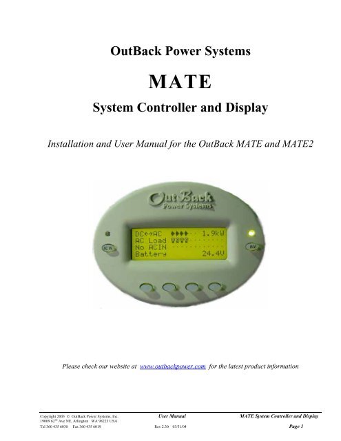
OutBack Power SystemsMATESystem Controller and DisplayInstallation and User Manual for the OutBack MATE and MATE2Please check our website at www.outbackpower.com for the latest product informationCopyright 2003 © OutBack Power Systems, Inc. User Manual MATE System Controller and Display19009 62 nd Ave NE, Arlington WA 98223 USATel 360 435 6030 Fax 360 435 6019 Rev 2.30 03/31/04 Page 1
MATE System Controller and Display User Manual Copyright 2003 © OutBack Power Systems, Inc.19009 62 nd Ave NE, Arlington WA 98223 USAPage 2 Rev 2.30 03/31/04 Tel 360 435 6030 Fax 360 435 6019
1.2 InstallationThe OutBack MATE is designed for surface mounting in an Indoor location. Keep the MATE out of direct sunlight to make thedisplay easier to view.The cabling from the MATE to the FX inverter/charger, MX60 PV MPPT charge controller or HUB is standard CAT5 typecomputer cable. Standard Ethernet CAT5 cable, can be found at any home improvement or computer store. Consult your localinspector for specific installation requirements. The current and voltage in the communication cable is limited to less than 30volts DC and is considered to be a “limited energy circuit”. No conduit should be required. Either CAT5 or CAT5e cable can beused. The MATE is shipped with 50’ of cable with the correct RJ45 connectors already installed. Longer or shorter cables canbe purchased pre-made or custom length cable can be made on site. Follow the cable manufactures’ instructions whenchoosing connectors and crimping tools.NOTE: The maximum tested cable length from the MATE to an OutBack product is 1000 feet (300 meters). Thisdistance can vary depending on cable routing and location. MATE cable that is run in a ‘noisy’environment (ex. MATE cable run in conduit with AC wiring) will suffer from signal degradation,impacting the maximum length the cable can be run without incurring transmission errors.The MATE should be wall mounted at just below the eye level of the typical user. No wiring box is required, although astandard 2 gang wiring box mounted in the horizontal position (as opposed to the typical vertical position of a light switch) canbe used for the cable entry. By bending the wiring at a 90 degree angle just after the connector, no wiring will be visible. TheRS-232 port for the PC computer is accessible from the bottom of the MATE when it is wall mounted. It also can be removedfrom the wall for connection of the serial cable.To install the MATE, unsnap the cover from the back of the MATE. There are four holes in this plate for mounting screws.After installing the mounting plate on the wall, connect the cable to the jack on the back of the circuit board. Snap the MATEonto the mounting plate and push any excess cable back into the wall.2.0 Basic Operation2.1 Power UpA soon as the MATE cable is plugged into a powered OutBack product, the MATE will power-up and display severalinformation screens. After a greeting and copyright screen appears, the next screen displayed has the MATE Code andScreen Revisions (see below).VersionCode a.aaSerial #xxxxxxxxScreen EE b.bbThe MATE’s operation and features are dictated by the code version. The serialnumber displayed matches the bar coded sticker on the MATE’s main PCB. This canbe viewed by removing the MATE’s back cover. The Screen EE version refers to themenu system currently loaded in the MATE. All of the version and serial numbersshould be referred to when contacting OutBack with MATE questions.For an explanation of the differing code versions, see the MATE firmware revisions topic under MATE Release Notes on theOutBack Power Systems User Forum found at: http://www.outbackpower.com/cgi-bin/Forum/ultimatebb.cgi .After the Version screen the MATE will display a connected devices screen (see below). If the MATE does not find theconnected device, refer to the section 7.0 Troubleshooting.MATE found an FX MATE found a MX MATE found no OutBack ProductSearchingfor DevicesFX FoundSearchingfor DevicesMX FoundSearchingfor DevicesNo Devices FoundCopyright 2003 © OutBack Power Systems, Inc User Manual . MATE System Controller and Display19009 62 nd Ave NE, Arlington WA 98223 USATel 360 435 6030 Fax 360 435 6019 Rev 2.30 03/31/04 Page 5
2.2 NavigationThis section of the <strong>manual</strong> will cover how to use the buttons on the MATE to navigate the menus.NOTE: The menu system displayed on the MATE will vary depending on the software version that the MATE wasprogrammed with at the time of manufacturing or during its last software upgrade.2.2.1 Menu StructureMAIN MENUSTATUSThe OutBack MATE uses a branching menu structure to displayvarious OutBack products operation modes and status. The menusare divided by product type and are categorized by type of settingsor information is being displayed.An example of the menu structure is shown to the right. All thescreens that show AC meters are grouped together in one menutree allowing the user to find the required meter with a minimum ofbutton presses.SETUPMXFXMETERSBATTERYOUTPUTVOLTAGEINPUTVOLTAGEINVERTERCURRENTThe top line of the MATE display will show the ‘path’ to the current menu; in thisexample it is STATUS/FX/METERS.STATUS/FX/METERS---------output122 vacvoltageDOWN UP TOP PORT2.2.2 <strong>Mate</strong> ButtonsAC ININVSoft KeysThe MATE uses a six button user interface to navigate the menus and to change setpoints of various OutBack products.Two buttons are dedicated for the FX inverters and are labeled ACIN and INV. These buttons are special in that they can bepressed at any time anywhere in the MATE menu structure, and they take you to the same screens. For this reason they arereferred to as ‘hot’ keys. Many common functions that need to be accessed often are found under the ACIN and INV button.The four lower buttons under the LCD are called ‘soft’ keys and are used for navigating around the menus and changingvalues. Each ‘soft’ key has various functions dependent on the label directly above it on the lower line of the LCD.NOTE: The lower line on the MATE is almost exclusively used for labels to the four soft keys below. This <strong>manual</strong>will denote soft key button presses as , where BUTTON corresponds with the label displayedon the screen directly above the soft key.MATE System Controller and Display User Manual Copyright 2003 © OutBack Power Systems, Inc.19009 62 nd Ave NE, Arlington WA 98223 USAPage 6 Rev 2.30 03/31/04 Tel 360 435 6030 Fax 360 435 6019
2.2.3 ‘SOFT’ KeysThe four buttons under the LCD are referred to as the ‘soft’ keys. Their operation is dependent on what their label says. Thelabel is the word on the bottom line of the LCD directly above the button.Soft keys used to navigate the menus are commonly labeled , , , , or .Soft keys that change settings are labeled either with the change they will make, such as : , , and , or ifthere are more then a couple values that the setting can be changed to, and are used to mean increase anddecrease, respectively.SETUP/FX/INPUT---P00ac transfer GRIDcontrolDOWN GRID GEN PORTIn this example, pressing will take you to the next setpoint screen inthe SETUP/FX/INPUT menu.SETUP/FX/INPUT---P00Input setupcompletedTOP SETUP MAINIn this example, pressing will take you to the first setpoint screen inthe SETUP/FX/INPUT menu. will return you to the SETUP/FXscreen, and will take you back to the Main screen.SETUP/FX/INPUT---P00ac transfer GRIDcontrolDOWN GRID GEN PORTIn this example, pressing will change the FX AC transfer control toGRID mode. Conversely, pressing will change the FX AC transfercontrol to GEN mode.SETUP/FX/INPUT---P00ac1/grid 60 aaclimitDOWN INC DEC PORTIn this example, pressing or will change the numerical value ofthe ac1/grid limit setting.ADV/FX/AUX-------P00aux output RemotefunctionDOWN INC DEC PORTIn this example, there are multiple operating modes for the aux output function.Pressing or will cycle through the available modes.Copyright 2003 © OutBack Power Systems, Inc User Manual . MATE System Controller and Display19009 62 nd Ave NE, Arlington WA 98223 USATel 360 435 6030 Fax 360 435 6019 Rev 2.30 03/31/04 Page 7
AC INAC INGEN START CONTROLCurrently:AutoOFF AUTO ON OKPressing the AC IN key a second time brings up the GEN START CONTROL screen.This screen allows the user to change the Advanced Generator Start (AGS) mode.Modes can only be changed when Advanced Generator Start is enabled (See section4.3 Advanced Generator Start for more information). When an OutBack HUB isemployed, the GEN START CONTROL only effects the FX that has been programmedas the AGS PORT in the AGS menu.Manually overrides AGS mode and shuts off the generatorAllows the MATE to automatically start and stop the generatoraccording to the settings programmed in the AGS menuManually overrides AGS mode and starts the generatorReturns to the point in the menu system where you entered the GENSTART CONTROL screenAC INAC INCHARGER CONTROLcurrently:OFF AUTOAC INOFFOKPressing the AC IN key a third time brings up the CHARGER CONTROL screen. Thisallows operation of the battery charger to be preset for when an AC source isavailable. The charger’s operation is independent of the inverter: you can set thecharger to come on when AC is available but have the inverter stay off when AC isdisconnected. When an OutBack HUB is employed, the CHARGER CONTROL onlyeffects the Master FX connected to PORT 1. The Master then echoes the command toall of its slaves.Disables all charger functions in the FXEnables automatic battery charging when an AC input source isconnectedReturns to the point in the menu system where you entered theCHARGER CONTROL screenAC INAC INCHARGER MODE CONTROLGlobal charger modeBULK EQ OKBULK CONTROLSTART STOPAC INCHARGER MODE CONTROLGlobal charger modeAC INOKBULK EQ OKPressing the AC IN key a fourth time brings up the CHARGER MODE CONTROLscreen. This screen allows the MATE to issue system wide (global) chargercommands. Both OutBack MX and FX products will respond to global chargercommands.Pressing brings up the BULK CONTROL screen, it will allow the user to startand/or stop a bulk charge cycle <strong>manual</strong>ly by pressing or respectively.Pressing brings up the EQUALIZE CONTROL screen.When the has been selected, two informational screen are displayed. Theuser then must answer before an equalize charging cycle is allowed to begin.Once the equalizing process has started, you can stop it at anytime by selecting from this same control screen.NOTE: For a global charger command to work, all of the OutBack products must be connected to a HUB. TheCHARGER MODE CONTROL effects both FX inverters and MX60 charge controllers. This requires thatthe FX and MX firmware versions support this feature (See section 7.0 Troubleshooting if this commandfails to function).Copyright 2003 © OutBack Power Systems, Inc User Manual . MATE System Controller and Display19009 62 nd Ave NE, Arlington WA 98223 USATel 360 435 6030 Fax 360 435 6019 Rev 2.30 03/31/04 Page 9
2.3 Common Screens2.3.1 The Main ScreenMAIN----------------------------12:00:30PSUM STATUS SETUP ADVAfter the power-up screens is the Main screen. It is the root, or home screen to the entire menu structure. If you get lostexploring the MATE’s many screens, press the two left soft keys simultaneously to return to the Main Screen from anywherein the menu system. Additionally, most menu branches end with a soft key labeled ; pressing this button will return youto the Main screen.2.3.2 Summary ScreensThe Summary screens provided by the MATE summarize the current status of all the OutBack products connected to it.Summary screens can be accessed from the Main screen by pressing the button or can be set to pop up like a screensaver after a delay (See section 3.3 Summary Screen Options for more setup information). Any MATE button pressed whilethe Summary screen is being displayed returns you to the screen that was active before the summary screen was displayed.If the MATE has one or more FXs connected to it, an FX summary screen will bedisplayed. It shows three bar graphs that summarize power flow in an FX system. Eachbar graph is made up of segments that roughly represent 500 watts of power per FXinverter connected (ex. With 2 FXs, each segment would represent 1000 Watts).DCAC ……. 0.0kwAC Load ……………...Buying ……………...Battery 25.6VDCAC >>>… 1.5kwThe DCAC bar graph represents the amount of power conversion happening in thesystem. It could be either the FX’s inverting and supplying AC power to the loads, or theFX’s charging the batteries with an AC input source. There is also a numerical read-out(in kilowatts) in the upper right hand corner.AC LoadBuying☼☼☼…...$$$$$…...The AC LOAD bar graph shows the amount of power that the FX is sending out its ACOUTPUT to power loads. This bar graph should equal the DCAC bar graph when allthe FXs in a system are inverting and will equal pass-thru loads when all the FXs areconnected to an AC source.The next bar graph denotes the power coming in or going out of the AC input terminals ofthe FX. Its label can be Buying when the AC input source is providing power to the FXand loads or Selling when the FX is exporting excess battery capacity back to the Grid.Battery 26.5VThe last line is for displaying battery voltage.If the MATE has one or more MX60 MPPT charge controllers attached to it, an MXsummary screen will be displayed. Each arrow displayed on the MX summary screen isequal to 500 watts per MX (ex. With 3 MXs, each arrow would represent 1500 watts).-------------------------------MX CHARGER 1.5kw>>>……….…………….Battery 25.6VNOTE: A MATE connected to a HUB with both FXs and MXs connected to it will switch between both types ofsummary screens every 20 seconds.MATE System Controller and Display User Manual Copyright 2003 © OutBack Power Systems, Inc.19009 62 nd Ave NE, Arlington WA 98223 USAPage 10 Rev 2.30 03/31/04 Tel 360 435 6030 Fax 360 435 6019
2.3.5 Advanced Screens cont.The Advanced menus allow the user to set most of the initial system setpoints for the FX, MX, and MATE. After entering thepassword choose the product you would like to change the Advanced settings for.The FX Advanced menus have categories like:• INV – Inverter setup• CHGR – Charger setpoints• GRID – Grid input setpoints• GEN – Generator input setpoints• AUX – FX Aux output settings• STACK – FX stacking setup• SELL – Grid-Tie setup• CAL – FX meter calibrationsNOTE: Not all Advanced menu screens are applicable to every model FX. An example would be a non Grid-Tie FXmay not display grid-tie parameters, or allow their adjustment.The MX Advanced menus only allow for the setup and control of the MX60s AUX output.The <strong>Mate</strong> Advanced menus contain the settings for:• HBX – High battery transfer• GRIDUSE – Time of day grid usage• AGS – Advanced generator startingThese advanced settings are covered in section 4.0 <strong>Mate</strong> Control ModesMATE System Controller and Display User Manual Copyright 2003 © OutBack Power Systems, Inc.19009 62 nd Ave NE, Arlington WA 98223 USAPage 12 Rev 2.30 03/31/04 Tel 360 435 6030 Fax 360 435 6019
2.4 Using the MATE with a HUBA HUB-4 or HUB-10 can be used to connect multiple OutBack products to the MATE. A HUB-10 communication managerallows a single MATE to control and monitor a maximum of ten OutBack products, while a HUB-4 is limited to four OutBackproducts.A HUB has 4 to 10 ports labeled 1-10 for various OutBackproducts to be plugged into.When setting-up a HUB based system to work with the MATE,several guidelines must be followed:A system comprised of all FX inverters must have theMaster FX plugged into Port 1 of the HUB.A system comprised of all MX charge controllers musthave one of the MXs plugged into Port 1.A system that has a mix of FXs and MXs must have theMaster FX plugged into Port 1 and have the slave FXsplugged into the next lowest numbered Ports. Forexample, if a system comprised of 4 FX’s and 2 MX’s,the FXs must be plugged into Ports 1 – 4; the MXs canbe plugged into any Port numbered greater then 4.When first powering-up the system, make sure all of the OutBack products are plugged into the HUB and powered beforeplugging the MATE into the HUB.When a MATE that is plugged into a HUB powers up, it will first display that it has foundthe HUB.Searchingfor DevicesHUB FoundNext it will display the Port Assignment screen. This screen shows all of the connecteddevices and what Port that they are found on. If a connected device is not shown on thisscreen, check that it is connected correctly and is powered up. Then either unplug andplug the MATE back into the HUB or use the REPOLL command described in the MATESetup section to force the MATE to rediscover all devices.Port Assignment1>FX 2>FX 3>FX 4>FX5>MX 6>MX 7>-- 8>--9>-- 10>-- 2M>--Once powered up, the MATE operation with a HUB is basically the same as when the MATE is directly connected to anOutBack product.STATUS/FX/METER------P01Output120vacVoltageDOWN UP TOP PORTThe most important difference is the Port Identifier in the upper right hand corner ofmost screens. The number after the P in P01 tells you that the meter reading currentlydisplayed on the screen is coming from the FX in Port 1. By pressing the button, you can cycle through all of the devices on the system.NOTE: When the user is in a menu that is dedicated to FXs, only FX Ports can be cycled through by pressing the button. Using the above system as an example, only P01 , P02 , P03 , and P04 will be displayedwhen the button is pushed while in a FX menu. Conversely, only P05 and P06 will be displayedwhen the button is pressed in an MX menu.NOTE: Any time a new device is plugged into a HUB or an existing device is moved to a different Port, the MATEmust be either unplugged and plugged back into the HUB or the REPOLL command described in theMATE Setup section must be used to force the MATE to rediscover all devices.Copyright 2003 © OutBack Power Systems, Inc User Manual . MATE System Controller and Display19009 62 nd Ave NE, Arlington WA 98223 USATel 360 435 6030 Fax 360 435 6019 Rev 2.30 03/31/04 Page 13
3.0 MATE SetupThis section will take you through the MATE specific setup, allowing you to change thedisplay settings, set the <strong>Mate</strong>s clock, and set various MATE control settings.Besides the clock display, the Main screen has four menu choices that correspond withthe four soft keys under them.For now we are interested in the SETUP menu. Press the soft key under the word. The next screen gives you the choice to set up a FX or the MATE; choose.The next screen displays the MATE code revision (3.00 in the example to the left) andseveral Setup choices. brings up a second screen of Setup choices.MAIN----------------------------12:00:30PSUM STATUS SETUP ADVSETUP---------------------------Choose product:FXMATESETUP/MATE/PAGE1---------<strong>Mate</strong> code rev: 300Choose category:CLOCK CNT GLOW PG2SETUP/MATE/PAGE2---------Choose category:PG1 SUMRY COMM MAIN3.1 Setting the clockPressing lets you choose to change the date and/or time displayedby the MATE. The button returns you to the previous screen. Correcttime and date are required for the <strong>Mate</strong> Control Modes discussed in section3.0 to operate correctly.SETUP/MATE/CLOCK--------Mo 1/01/0312:00:00PBACK DATE TIME3.2 Contrast adjustment sets the desired contrast level. increases the contrast level,; decreases the contrast level. The LCD on the MATE automaticallyadjusts for most temperature changes, but the contrast might need to bechanged for ambient lighting conditions.SETUP/MATE/CNT------------Contrast: 30%BACK INCDEC3.2 Backlight adjustment sets the desired backlight mode, level, and on time. Pressing brings up several more backlightsettings. controls brightness and is adjustable from 0 to 100%. allows user to set the backlight to always off, auto-off after a time, oralways on by selecting , , or , respectively.SETUP/MATE/GLOW---------Backlight controlsBACK LEVEL MODE TIME sets the auto-off time limit from 1 to 60 minutes. This is how long the MATE waits after the last button pressto turn off the backlight. Once the backlight has turned off, any button press on the MATE will turn it back on.NOTE: The MATE clock does not automatically adjust for daylight savings time.MATE System Controller and Display User Manual Copyright 2003 © OutBack Power Systems, Inc.19009 62 nd Ave NE, Arlington WA 98223 USAPage 14 Rev 2.30 03/31/04 Tel 360 435 6030 Fax 360 435 6019
3.3 Summery Screen Options brings up Summary screen options. allows you to choose the type of summary screen(s) displayed. Yourchoice is: ROLL, FXONLY, MXONLY, or NONE. Roll switches between FX andMX screens automatically if both types of products are connected to the MATE.FXONLY or MXONLY only display the FX or MX summary screen if therespective product is connected. NONE disables the summary screen frompopping up automatically, it can still be accessed via the button on theMain screen.SETUP/MATE/SUMMARY--Summary controlBACK TYPETIME brings up a delay setting for how long it takes for a summary screen to be displayed. Information on thesummary screens is covered in section 2.3.2 Summary Screens.3.4 Communications Options deals with MATE communication options. Pressing brings up several options that can bechanged. forces the MATE to ‘rediscover’ all the OutBack devices it isconnected to. This is used any time an OutBack devices is moved or added toa HUB.SETUP/MATE/COMM-------Choose category:BACK REPOLL PC DEBUG will enable or disable the RS232 communications port of the MATE. This setting must be enabled if you useany third party logging or control software. allows communications errors involving the OutBack HUB to betracked.On the DEBUG screen, first press to reset the error counting display;then press to bring up a list of HUB ports with a count ofcommunications errors for each port.In the example to the right, Port 4 has a large number of errors detected(04:025 means Port 4: showing 25 errors). Pressing any key will take you tothe SETUP/MATE/COMM screen, which will allow the error counts to be resetusing the button. The DEBUG screen can be redisplayed by using the button, or the user can get back to the SETUP menu by using the button.SETUP/MATE/COMM-------Comm. errors:BACKVIEW RSET00:000 01:000 02:00003:000 04:025 05:00106:001 07:001 08:00109:001 10:001 2M:001Use the information on the DEBUG screen to locate the problem device. Make sure that it’s DC breaker is on and thatit is operating correctly. Check or replace CAT5 cables running from the HUB to that device.4.0 <strong>Mate</strong> Control ModesThe OutBack MATE is capable of several advanced modes of operation. These modes require that the MATE remainconnected to at least one OutBack FX inverter at all times. The first two modes automatically use the MATE commands DROPand USE to allow the FX to connect to an AC input source only at specified times or battery levels.A <strong>manual</strong> USE or Drop command can be issued by pressing the button until the AC INPUT CONTROL screen isreached. tells the FX to go ahead and use the AC input source while will tell the FX to ignore any AC Inputsource.The settings for all of the MATE Control Modes are under the ADVANCED menu. Fromthe Main screen press and enter the password for access to the ADVANCEDmenus. Once the ADVANCED menu has been entered, choose and youshould see a screen similar to the one on the right. At this point you can choose whichMATE Control Mode you would like to setup.ADV/MATE--------------------Choose category:HBX GRIDUSE AGS ADVCopyright 2003 © OutBack Power Systems, Inc User Manual . MATE System Controller and Display19009 62 nd Ave NE, Arlington WA 98223 USATel 360 435 6030 Fax 360 435 6019 Rev 2.30 03/31/04 Page 15
4.1 HBX ModeHBX stands for high battery transfer. It is a mode primarily used in applications that have enough RE power production to meetthe needs of the loads most of the time. HBX mode will only allow the FX to connect to an AC source if the battery voltage hasfallen below a programmable setpoint for a user configurable amount of time. The MATE will then allow the FX to remainconnected to the AC source until the battery voltage has risen above a second setpoint for a programmable amount of time.NOTE: HBX Mode in a multi-inverter installation utilizing a HUB-4 or HUB-10 will control the Master FX in port 1.The Master will then instruct any stacked slaves to USE or DROP the AC input source.HBX-USE GRID SETPOINT: This is the voltage setpoint for when the FX will be allowedto USE its AC input source. The battery voltage must remain below this voltage for theamount of time set by HBX-USE GRID DELAY for a USE to be issued. and buttons can be used to change the value.ADV/MATE/HBX--------------hbx-use24.0 vdcgrid setpointDOWN ADV INC DECHBX-USE GRID DELAY: This setpoint is the amount of time that battery voltage mustremain below HBX-USE GRID SETPOINT before a USE command is sent. It can rangefrom 00.1 hrs to 24.0 hrs in 0.1 hour increments.ADV/MATE/HBX--------------hbx-use01.0 hrsgrid delayDOWN UP INC DECHBX-DROP GRID SETPOINT: This is the voltage at which the FX will be allowed toDROP it’s AC input source. The battery voltage must remain above this voltage for theamount of time set by HBX-DROP GRID DELAY for a DROP to be issued.ADV/MATE/HBX--------------hbx-drop26.0 vdcgrid setpointDOWN UP INC DECHBX-DROP GRID DELAY: This setpoint is the amount of time that battery voltage mustremain above HBX-DROP GRID SETPOINT before a DROP command is sent. It canrange from 00.1 hrs to 24.0 hrs in 0.1 hour increments.ADV/MATE/HBX--------------hbx-drop01.0 hrsgrid delayDOWN UP INC DECAC INPUT CONTROL: With this screen, HBX Mode can be enabled or disabled.Pressing allows you to change the current mode.Before enabling HBX Mode make sure that the FX is in DROP mode by pressing. The screen should indicate DROP mode. Enable HBX by pressing the button. The screen will now indicate that the MATE is running in HBX mode bydisplaying the current state, USE or DROP followed by –HBX.To disable HBX Mode, simply press the button again. After disabling HBX makesure to reset the DROP or USE to whatever state is desired.Pressing returns you to the HBX menu where you can exit back to theADVANCED menu by using either the or buttons.ADV/MATE/HBX--------------ac inputUSEcontrolDOWN UP CHANGEADV/MATE/HBX--------------ac input DROP-HBXcontrolDROP USE HBX DONENOTE: Even with HBX mode enabled, the user can issue <strong>manual</strong> DROP or USE commands using the ACINPUT CONTROL found under the ACIN button.MATE System Controller and Display User Manual Copyright 2003 © OutBack Power Systems, Inc.19009 62 nd Ave NE, Arlington WA 98223 USAPage 16 Rev 2.30 03/31/04 Tel 360 435 6030 Fax 360 435 6019
4.2 Grid-Use ModeGrid-Use mode is for time of day based grid usage. It allows you to program the time of day that the FX will connect to the ACinput source. You must ensure that the time and date is properly programmed for Grid-Use mode to function properly (Seesection 3.0 MATE Setup).Grid-Use mode will allow the user to choose the time of day that the FX will USE the AC input source, and is good for takingadvantage of cheaper utility rates during off-peak hours. Grid-Use time can be programmed separately for weekday vs.weekend connect times. Care must be taken when programming weekday and weekend times that encompass USE periodspast midnight (12:00 am). The user must take into account weekday USE periods that will end on a Saturday.Example #1:Weekday Start 6:00 PMWeekend Start 12:00 AMWeekday Stop 6:00 AMWeekend Stop 12:00 AMThe weekend USE period has been left at its default. Any time that a Start time equals a Stop time, noaction will be taken. This results in the time period being ignored. The above settings will have the followingresults:Mon – Thr evenings at 6PM the MATE will issue a USE command to the FX allowing the AC input source to beused. Additionally, every morning (Mon – Thr) at 6AM a DROP will be issued. On FRI evening at 6PM a USEwill be issued but since the Weekend Start and Stop times are equal, the weekend use time is disabled NoDROP will be issued until Mon morning at 6AM.Example #2:Weekday Start 6:00 PMWeekend Start 4:00 PMWeekday Stop 6:00 AMWeekend Stop 8:00 AMMon – Thr evenings at 6PM the MATE will issue a USE command to the FX allowing the AC input source to beused. Additionally, every morning (Mon – Thr) at 6AM a DROP will be issued. On FRI evening at 6PM a USEwill be issued. The following morning is a weekend (Sat) so a DROP command will be issued at 8AM. Satevening at 4PM the FX will USE again until Sun morning at 8AM. Sun evening at 4PM a USE time period willstart, ending on Mon morning at 6AM.NOTE: If the battery falls below the FX Low Battery Cut-off voltage, the FX will automatically connect to theAC input source regardless of the GRID-USE time of day setting.NOTE: Because GRID-USE mode uses the DROP and USE commands, it cannot be enabled at the sametime as HBX mode. Enabling GRID-USE will automatically disable HBX mode.Grid-Use cont. on next pageCopyright 2003 © OutBack Power Systems, Inc User Manual . MATE System Controller and Display19009 62 nd Ave NE, Arlington WA 98223 USATel 360 435 6030 Fax 360 435 6019 Rev 2.30 03/31/04 Page 17
GRID-USE ENABLE: This screen actually turns GRID-USE mode or .Make sure that all of the GRID-USE parameters are set before enabling GRID-USEmode. The GRID-USE settings can be accessed by using the button.ADV/MATE/GRIDUSE--------griduse enable: OffDOWN ADV OFF ONWEEKDAY GRID-USE START: This setting is the time during the week (Mon – FRI)that a USE will be issued to an FX, allowing the FX to connect to the AC input source.The time displayed is the current setting. To change the time press .ADV/MATE/GRIDUSE--------weekday 12:00Agriduse startDOWN ADV CHANGEUsing the and buttons, set the hour to the desired time. Then press.WEEKDAY GRDUSE STARTAdj hour 12:00ADOWNINC DECUsing the and buttons, set the minutes to the desired time. Then press.WEEKDAY GRDUSE STARTAdj min 12:00AINC DEC DONEWEEKDAY GRID-USE STOP: This setting is the time during the week (Mon – FRI) thata DROP will be issued to an FX, forcing FX to disconnect from the AC input source. Thetime displayed is the current setting. To change the time press .ADV/MATE/GRIDUSE--------weekday 12:00Agriduse stopDOWN ADV CHANGEWEEKEND GRID-USE START: This setting is the time during the weekend (Sat & Sun)that a USE will be issued to an FX, allowing the FX to connect to the AC input source.The time displayed is the current setting. To change the time press .ADV/MATE/GRIDUSE--------weekend 12:00Agriduse startDOWN ADV CHANGEWEEKEND GRID-USE STOP: This setting is the time during the weekend (Sat & Sun)that a DROP will be issued to an FX, forcing FX to disconnect from the AC input source.The time displayed is the current setting, to change the time press .ADV/MATE/GRIDUSE--------weekend 12:00Agriduse stopDOWN ADV CHANGENOTE: A Start time that equals a Stop time disables USE time for that period (weekday or weekend).MATE System Controller and Display User Manual Copyright 2003 © OutBack Power Systems, Inc.19009 62 nd Ave NE, Arlington WA 98223 USAPage 18 Rev 2.30 03/31/04 Tel 360 435 6030 Fax 360 435 6019
4.3 Advanced Generator Start ModeAdvanced Generator Start (AGS) Mode utilizes the AUX output found on FX inverters and is compatible with any 2 wire startgenerator. AGS allows the user to choose a variety of conditions that will start a generator by energizing the FX AUX output.AGS will start the generator anytime one or more of the Gen Start conditions are true, and will stop the generator only when allof the conditions are false.After AGS starts a generator, the FX must connect to the generator within a 5 minute window. If the FX fails to connect within5 minutes, a Genstart error is displayed by the MATE, and all subsequent AGS conditions will be ignored until the AGS modehas been reset. AGS mode can be reset by using the GEN START CONTROL found by pressing the button twice.Pressing and then resets all AGS parameters. The generator can also be <strong>manual</strong>ly started using the GENSTART CONTROL screen by pressing . If the user wants the generator to auto stop after a charge cycle is complete,the user can press the button after the generator has been started by pressing .The following is a discussion of all the AGS setup parameters and start condition available to the user:4.3.1 AGS SetupThe AGS Setup menu contains the following general settings that define how the rest of the AGS routines will work:AGS Port:The MATE can use any AUX output of an FX that is connected to it eitherdirectly or via an OutBack HUB-4 or HUB-10. If a HUB is used, the MATEmust be told what Port that the desired FX resides on. If no HUB is used andthe MATE is directly plugged into an FX, then the AGS Port needs to be setto 0 (zero). If a HUB is used, the numbered jack that the desired FX isconnected to on the HUB should be set as the AGS Port.MATE/AGS/SETUP-----------Ags port: 0DOWN AGS INC DECExample:A MATE is connected to a HUB-10 that has four FXs and three MXs connected to it. The FXs are plugged intoPorts 1 – 4, as labeled on the HUB, and the MXs are plugged into Ports 5 – 7. The FX connected to Port #3 willhave its AUX output wired to the generator, so the AGS Port should be set to ‘3’.AGS Control:This screen allows the AGS mode to be changed. Pressing brings up a screen that allows the user to switch AGS from Manual to Auto.ADV/MATE/AGS/SETUP-----Ags control: MAN-OffAn de-energizes the FX AUX output and stops the generatorregardless of any AGS setting; this is displayed as MAN – OFF.DOWN UPCHANGEAn will allow the AGS settings to start and stop the generatorautomatically, and is displayed as either AUTO – ON (when the generator isrunning), or AUTO – OFF (when the generator is stopped).An will energize the FX AUX output and start the generator regardlessof any AGS setting, this is displayed as MAN – ON.AGS Enabled:This is the overall control for AGS. If AGS is not enabled, none of the AGSsettings or controls will work.DC Genset:A Yes means that you have a DC generator and that AGS routines whichnormally stop the generator upon the FX going to Float or Silent will insteadstop the generator when the VDC Genstop setting is reached.VDC Genstop:This voltage setting will terminate a Voltage Start Genstart when the batteryvoltage remains above it for 15 min regardless of the DC Genset setting.GEN START CONTROLcurrently: MAN-OffOFF AUTO ON OKADV/MATE/AGS/SETUP-----Ags enabled:NODOWN UP NO YESADV/MATE/AGS/SETUP-----Dc genset:NODOWN UP NO YESADV/MATE/AGS/SETUP-----Vdc genstop: 38.0 vdcDOWN UP INC DECCopyright 2003 © OutBack Power Systems, Inc User Manual . MATE System Controller and Display19009 62 nd Ave NE, Arlington WA 98223 USATel 360 435 6030 Fax 360 435 6019 Rev 2.30 03/31/04 Page 19
4.3.2 Quiet TimeQuiet Time is a time period during which the MATE will not allow most AGS settings to start the generator. This is usually setupas night time when a running generator would be an annoyance. Quiet Times can be set individually for weekday andweekend, and consist of a Quiet Time Start and a Quiet Time Stop.WEEKDAY START:Weekday Quiet Time start is the beginning of the quiet time period for Mon -Fri, most AGS start conditions will be stopped at this time. Press to adjust the hour and minutes settings.ADV/MATE/AGS/QT----------weekday: 12:00Aquiet time startDOWN AGS CHANGEWEEKDAY STOP:Weekday Quiet Time stop is the end of the quiet time period for Mon - Fri.Press to adjust the hour and minutes settings.ADV/MATE/AGS/QT----------weekday: 12:00Aquiet time stopDOWN UP CHANGEWEEKEND START:Weekend Quiet Time start is the beginning of the quiet time period for Sat &Sun, most AGS start conditions will be stopped at this time. Press to adjust the hour and minutes settings.ADV/MATE/AGS/QT----------weekend: 12:00Aquiet time startDOWN UP CHANGEWEEKEND STOP:Weekend Quiet Time stop is the end of the quiet time period for Sat & Sun.Press to adjust the hour and minutes settings.ADV/MATE/AGS/QT----------weekend: 12:00Aquiet time stopDOWN UP CHANGE4.3.3 Voltage StartThere are three voltage start setpoints in AGS Mode that the user can adjust. After a generator is started due to a VoltageStart setting, it will be stopped when the FX reaches Float or Silent mode, or based on the VDC Genstop setting in AGSSetup menu previously explained.24 Hour voltage setpoint:If the battery voltage falls below this setpoint, a 24 hour timer starts to countdown. On reaching zero, a genstart is sent to the FX inverter unless it iscurrently Quiet Time.ADV/MATE/AGS/VSTART--Volt start24.4 vdc24 hr settingDOWN AGS INC DEC2 Hour voltage setpoint:If the battery voltage falls below this setpoint, a 2 hour timer starts to countdown. On reaching zero, a genstart is sent to the FX inverter unless it iscurrently Quite Time.ADV/MATE/AGS/VSTART--Volt start23.6 vdc2 hr settingDOWN UP INC DEC2 Minute voltage setpoint:If the battery voltage falls below this setpoint, a 2 minute timer starts to countdown. On reaching zero, a genstart is sent to the FX inverter even if it iscurrently Quite Time.ADV/MATE/AGS/VSTART--Volt start22.0 vdc2 min settingDOWN UP INC DECMATE System Controller and Display User Manual Copyright 2003 © OutBack Power Systems, Inc.19009 62 nd Ave NE, Arlington WA 98223 USAPage 20 Rev 2.30 03/31/04 Tel 360 435 6030 Fax 360 435 6019
4.3.6 ExerciseAn Exercise time can be set by choosing a day of the week (Sun – Sat), a start time of day (12AM – 11:59PM), and a exerciseperiod (1 – 240 minutes). On the first occurrence of the chosen day of the week each month, at the programmed start time, thegenerator will start and run for the programmed period.EXERCISE START DAY (exstartday):This is the day of the week that the generator will start on. This can be set toMon – Fri, and Sat or Sun, depending on what day each month a generatorexercise period should be run. The setting “- -“ disables any exercise period.ADV/MATE/AGS/EX----------exstartday: --DOWN AGS INC DECEX START TIME:This setting controls at what time on the Exercise Start Day the generator willstart it’s exercise period. Press to adjust the hour and minutessettings.ADV/MATE/AGS/EX----------Ex start time: 12:00ADOWN UP CHANGEEX PERIOD:Ex Period is how long a generator exercise period will be. and can change the value between 1 – 240 minutes.ADV/MATE/AGS/EX----------Ex period: 15 minDOWN UP INC DECMATE System Controller and Display User Manual Copyright 2003 © OutBack Power Systems, Inc.19009 62 nd Ave NE, Arlington WA 98223 USAPage 22 Rev 2.30 03/31/04 Tel 360 435 6030 Fax 360 435 6019
5.0 Menu MapAC Input LEDIndicator(yellow)InverterLED Indicator(green)DedicatedInverterControl“HOT” KeyDedicatedInverterControl“HOT” KeyVariable “Soft” Keyseach one of the soft keys corresponds to a wordon the bottom line of the LCD displayThe menu system displayed on the MATE will vary depending on the softwareversion that the MATE was programmed with at the time of manufacturing orduring its last software upgrade.The following pages give a basic idea of the menu structure and how younavigate through the menu system to the different programming levels. Somechanges from these specific displays may be present in your installation.Copyright 2003 © OutBack Power Systems, Inc User Manual . MATE System Controller and Display19009 62 nd Ave NE, Arlington WA 98223 USATel 360 435 6030 Fax 360 435 6019 Rev 2.30 03/31/04 Page 23
CONTROL KEYSINVInv Hot KeyINVERTER CONTROLcurrently: ONOFF SRCH ON OKAC INAC IN Hot KeyAC INPUT CONTROLcurrently: DROPDROP USEAC INOKsecond pressGEN START CONTROLcurrently: MAN-OFFOFF AUTO ONAC INthird pressCHARGER CONTROLcurrently: OFFOFF AUTOAC INOKOKfourth pressCHARGER MODE CONTROLGlobal charger modeBULK EQ OKSummary ScreensMAIN----------------6:54:42PSUM STATUS SETUP ADV↓DCAC. . . . 0.0kWAC Load . . . . . .Buying . . . . . .Battery 25.6V- - - - - - - - - -MX CHARGER. . . . .Battery 25.6VSTATUS MENU--FXMODESMAIN----------------6:54:42PMSUM STATUS SETUP ADV↓STATUS--------------choose product:FXMX↓STATUS/FX/PAGE1-----choose category:MODES METER BATT PG2↓STATUS/FX/MODE---P00inv control: ONCHANGEDOWN STAT MODE PORT↓INVERTER CONTROLcurrently: ONOFF SRCH ON OK↓STATUS/FX/MODE---P00inv control: ONCHANGEDOWN STAT MODE PORT↓STATUS/FX/MODE---P00ac in control: USECHANGEDOWN UP MODE PORT↓AC INPUT CONTROLcurrently:DROP USEUSEOK↓STATUS/FX/MODE---P00ac in control: USECHANGEDOWN UP MODE PORT↓STATUS/FX/MODE---P00chr control: AUTOCHANGEDOWN UP MODE PORT↓CHARGER CONTROLcurrently:OFF AUTOAUTOOK↓STATUS/FX/MODE---P00chr control: AUTOCHANGEDOWN UP MODE PORT↓STATUS/FX/MODE---P00aux control: AUTOCHANGEDOWN UP MODE PORT↓AUX OUTPUT CONTROLcurrently: AUTOOFF AUTO ONOKMODES cont.STATUS/FX/MODE---P00aux control: AUTOCHANGEDOWN UP MODE PORT↓STATUS/FX/MODE---P00eq control: NOCHANGEUP MODE PORT↓EQUALIZE CONTROLeq enabled: NOSTOP STARTMETERSOKMAIN----------------6:54:42PSUM STATUS SETUP ADV↓STATUS--------------choose product:FX MX↓STATUS/FX/PAGE1-----choose category:MODES METER BATT PG2↓MODE: SILENT P00inv 0.0kw zer 0.0kwchg 0.0kw buy 0.0kwDOWN STATUS PORT↓STATUS/FX/METERS—P00output 122 vacvoltageDOWN UP TOP PORT↓STATUS/FX/METERS—P00input 122 vacvoltageDOWN UP TOP PORT↓STATUS/FX/METERS—P00inverter 0.0 aaccurrentDOWN UP TOP PORT↓STATUS/FX/METERS—P00charger 0.0 aaccurrentDOWN UP TOP PORT↓STATUS/FX/METERS—P00input 0.0 aaccurrentDOWN UP TOP PORT↓STATUS/FX/METERS—P00sell0.0 aaccurrentDOWN UP TOP PORT↓cont. on next pageMATE System Controller and Display User Manual Copyright 2003 © OutBack Power Systems, Inc.19009 62 nd Ave NE, Arlington WA 98223 USAPage 24 Rev 2.30 03/31/04 Tel 360 435 6030 Fax 360 435 6019
STATUS MENU--FXMETERS contSTATUS/FX/METERS—P00FX firmware 50revisionDOWN UP TOP PORT↓STATUS/FX/METERS—---end of meter menuUP TOP STATUSBATTERYMAIN----------------6:54:42PSUM STATUS SETUP ADV↓STATUS--------------choose product:FX MX↓STATUS/FX/PAGE1-----choose category:MODES METER BATT PG2↓STATUS/FX/BATT---P00battery 25.0 vdcactualDOWN STATUS PORT↓STATUS/FX/BATT---P00battery 25.0 vdctemp compensatedDOWN UP TOP PORT↓STATUS/FX/BATT---P00absorb 28.8 vdcsetpointDOWN UP TOP PORT↓STATUS/FX/BATT---P00absorb 01.5 hrstime remainingDOWN UP TOP PORT↓STATUS/FX/BATT---P00float 26.8 vdcsetpointDOWN UP TOP PORT↓STATUS/FX/BATT---P00float 00.8 hrstime remainingDOWN UP TOP PORT↓STATUS/FX/BATT---P00refloat 25.0 vdcsetpointDOWN UP TOP PORT↓STATUS/FX/BATT---P00equalize 28.8 vdcsetpointDOWN UP TOP PORT↓BATTERY contSTATUS/FX/BATT---P00equalize 02.0 hrstime remainingDOWN UP TOP PORT↓STATUS/FX/BATT---P00batt temp. 255(not in degree C/F)DOWN UP TOP STATUS↓STATUS/FX/BATT--—---end of battery menuUP TOP STATUSERRORSMAIN----------------6:54:42PSUM STATUS SETUP ADV↓STATUS--------------choose product:FX MX↓STATUS/FX/PAGE1-----choose category:MODES METER BATT PG2↓STATUS/FX/PAGE2-----choose category:PG1 ERROR WARN PG3↓STATUS/FX/ERROR—-P00low ac output NOvoltageDOWN STATUS PORT↓STATUS/FX/ERROR—-P00stackingNOerror detectedDOWN UP TOP PORT↓STATUS/FX/ERROR—-P00inverterNOovertempDOWN UP TOP PORT↓STATUS/FX/ERROR—-P00low battery NOvoltageDOWN UP TOP PORT↓STATUS/FX/ERROR—-P00phase loss NOerrorDOWN UP TOP PORT↓STATUS/FX/ERROR—-P00high battery NOerrorDOWN UP TOP PORT↓ERRORS contSTATUS/FX/ERROR—-P00ac output NOshortedDOWN UP TOP PORT↓STATUS/FX/ERROR—-P00ac output NObackfeedDOWN UP TOP PORT↓STATUS/FX/ERROR—----end of error menuUP TOP STATUSWARNINGSMAIN----------------6:54:42PSUM STATUS SETUP ADV↓STATUS--------------choose product:FX MX↓STATUS/FX/PAGE1-----choose category:METER BAT ERROR PG2↓STATUS/FX/PAGE2-----choose category:PG1 ERROR WARN PG3↓STATUS/FX/WARN---P00ac in freq NOto highDOWN STATUS PORT↓STATUS/FX/WARN---P00ac in freq NOto lowDOWN UP TOP PORT↓STATUS/FX/WARN---P00ac in voltage NOto highDOWN UP TOP PORT↓STATUS/FX/WARN---P00ac in voltage NOto lowDOWN UP TOP↓STATUS/FX/WARN---P00ac inputNOcurrent exceeds maxDOWN UP TOP PORT↓STATUS/FX/WARN---P00temperature NOsensor faultDOWN UP TOP PORT↓cont. on next pageCopyright 2003 © OutBack Power Systems, Inc. User Manual MATE System Controller and Display19009 62 nd Ave NE, Arlington WA 98223 USATel 360 435 6030 Fax 360 435 6019 Rev 2.30 03/31/04 Page 25
STATUS MENU--FXWARNINGS contSTATUS/FX/WARN---P00internal comm NOerror detectedDOWN UP TOP PORT↓STATUS/FX/WARN---P00internal fan NOerror detectedDOWN UP TOP PORT↓STATUS/FX/WARN---P00Air temp 204DOWN UP TOPPORT↓STATUS/FX/WARN---P00Fet temp 204DOWN UP TOPPORT↓STATUS/FX/WARN---P00Cap temp 204DOWN UP TOPPORT↓STATUS/FX/WARN------end of warnings menuUP TOP STATUSDESCONNECTREASONSMAIN----------------6:54:42PMAIN----------------6:54:42PSELLSUM STATUS SETUP ADV↓STATUS--------------choose product:FX MX↓STATUS/FX/PAGE1-----choose category:METER BAT ERROR PG2↓STATUS/FX/PAGE2-----choose category:PG1 ERROR WARN PG3↓STATUS/FX/PAGE3-----choose category:PG2 DISCON SELL MAIN↓STATUS/FX/DISCON-P00ac in freq NOto highDOWN STATUS PORTFX MX↓reasonSTATUSSTATUS/FX/DISCON-P00ac in freq NOto lowDOWN STATUS PORT↓STATUS/FX/DISCON-P00ac in voltage NO> maxDOWN UP TOP PORT↓STATUS/FX/DISCON-P00ac in voltage< minNOSUM STATUS SETUP ADV↓STATUS--------------choose product:↓STATUS/FX/PAGE1-----choose category:METER BAT ERROR PG2↓STATUS/FX/PAGE2-----choose category:PG1 ERROR WARN PG3↓STATUS/FX/PAGE3-----choose category:PG2 DISCON SELL MAIN↓STATUS/FX/SELL---P00Stop sell 255PORTMAIN MENU SHORTCUTPressing the left two keys on the MATEat the same time from anywhere in themenu system takes you to the MAIN menuCopyright 2003 © OutBack Power Systems, Inc. User Manual MATE System Controller and Display19009 62 nd Ave NE, Arlington WA 98223 USATel 360 435 6030 Fax 360 435 6019 Rev 2.30 03/31/04 Page 26
STATUS MENU--MXMODESMAIN----------------6:54:42PMSUM STATUS SETUP ADV↓STATUS--------------choose product:FXMX↓STATUS/MX-----------choose category:MODE METER SETP MAIN↓STATUS/MX/MODE--—P00charger mode: BULKDOWNSTATUS PORT↓STATUS/MX/MODE--—P00aux relay DIVERTmodeDOWN UP TOP PORT↓STATUS/MX/MODE--—P00aux relay state: ONDOWN UPTOP PORT↓STATUS/MX/MODE--—---end of mode menuUP TOP STATUSMETERSMAIN----------------6:54:42PMSUM STATUS SETUP ADV↓STATUS--------------choose product:FXMX↓STATUS/MX-----------choose category:MODE METER SETP MAIN↓MODE: SILENT P00pv 000 v bat 00.0 vin 00 a out 00 aDOWN STATUS PORT↓STATUS/MX/METER-—P00chargerwwattsDOWN UP TOP PORT↓METERS contSTATUS/MX/METER-—P00chargerkwhkwhrsDOWN UP TOP PORT↓STATUS/MX/METER-—P00chargeradcamps dcDOWN UP TOP PORT↓STATUS/MX/METER-—P00batteryvdcvoltageDOWN UP TOP PORT↓STATUS/MX/METER-—P00panelvdcvoltageDOWN UP TOP PORT↓STATUS/MX/METER-—---end of meter menuUP TOP STATUSSETPOINTSMAIN----------------6:54:42PMSUM STATUS SETUP ADV↓STATUS--------------choose product:FXMX↓STATUS/MX-----------choose category:MODE METER SETP MAIN↓STATUS/MX/SETP--—P00absorbvdcvoltageDOWN STATUS PORT↓STATUS/MX/SETP--—P00floatvdcvoltageDOWN UP TOP PORT↓STATUS/MX/SETP--—---end of setpoint menuUP TOP STATUSMAIN MENU SHORTCUTPressing the left two keys on the MATEat the same time from anywhere in themenu system takes you to the MAIN menuCopyright 2003 © OutBack Power Systems, Inc User Manual . MATE System Controller and Display19009 62 nd Ave NE, Arlington WA 98223 USATel 360 435 6030 Fax 360 435 6019 Rev 2.30 03/31/04 Page 27
SETUP MENU--FXSEARCHMAIN----------------6:54:42PSUM STATUS SETUP ADV↓SETUP---------------choose product:FXMATE↓SETUP/FX------------choose category:SRCH INPUT MAIN↓SETUP/FX/SEARCH—-P00search 0sensitivityDOWN INC DEC PORT↓SETUP/FX/SEARCH—-P00search 2 cyclespulse lengthDOWN INC DEC PORT↓SETUP/FX/SEARCH—-P00search 30 cyclespulse spacingDOWN INC DEC PORT↓SETUP/FX/SEARCH-----search setupcompletedTOP SETUP MAININPUTMAIN----------------6:54:42PSUM STATUS SETUP ADV↓SETUP---------------choose product:FXMATE↓SETUP/FX------------choose category:SRCH INPUT MAIN↓SETUP/FX/INPUT---P00ac transfer GRIDcontrolDOWN GRID GEN PORT↓SETUP/FX/INPUT---P00ac1/grid 60 aaclimitDOWN INC DEC PORT↓SETUP/FX/INPUT---P00ac2/gen 30 aaclimitDOWN INC DEC PORT↓SETUP/FX/INPUT------input setupcompletedTOP SETUP MAINSETUP MENU--MATEMAIN MENU SHORTCUTPressing the left two keys on the MATEat the same time from anywhere in themenu system takes you to the MAIN menuMATEMAIN----------------6:54:42PSUM STATUS SETUP ADV↓SETUP---------------choose product:FXMATE↓SETUP/MATE/PAGE1----choose category:CLOCK CNT GLOW PAGE2↓SETUP/MATE/PAGE2----choose category:PG1 SUMRY COMM MAINDATE / TIMESETUP/MATE/PAGE1----choose category:CLOCK CNT GLOW PAGE2↓SETUP/MATE/CLOCK----Tu 12/10/024:00:22PBACK DATE TIMECONTRASTSETUP/MATE/PAGE1----choose category:CLOCK CNT GLOW PAGE2↓SETUP/MATE/CNT------contrast: 30%BACK INC DECBACKLIGHTSETUP/MATE/PAGE1----choose category:CLOCK CNT GLOW PAGE2↓SETUP/MATE/GLOW----Backlight controlsBACK LEVEL MODE TIMEMATE System Controller and Display User Manual Copyright 2003 © OutBack Power Systems, Inc.19009 62 nd Ave NE, Arlington WA 98223 USAPage 28 Rev 2.30 03/31/04 Tel 360 435 6030 Fax 360 435 6019
SETUP MENU--MATESUMMARYSETUP/MATE/PAGE1----choose category:CLOCK CNT GLOW PG2↓SETUP/MATE/PAGE2----choose category:PG1 SUMRY COMM MAIN↓SETUP/MATE/SUMMARY--summary controlsBACK TYPE TIME MAINCOMMSETUP/MATE/PAGE1----choose category:CLOCK CNT GLOW PG2↓SETUP/MATE/PAGE2----choose category:PG1 SUMRY COMM MAIN↓SETUP/MATE/COMM-----choose category:BACK REPOLL PC DEBUGMAIN MENU SHORTCUTPressing the left two keys on the MATEat the same time from anywhere in themenu system takes you to the MAIN menuINVERTERMAIN----------------6:54:42PSUM STATUS SETUP ADV↓ADV/SETTINGS/WARNINGchanges made couldadversely effectsystem performance↓ ↓ ↓ ↓ADV/PASSWORD--------enter the password:132ENTER INC DEC EXIT↓ADV-----------------choose product:FX MX MATE MAIN↓ADV/FX/PAGE1--------choose category:ADV INV CHGR PG2↓ADV/FX/INVERTER—-P00search 6sensitivityDOWN INC DEC PORT↓ADV/FX/INVERTER—-P00search 2 cyclespulse lengthDOWN INC DEC PORT↓ADV/FX/INVERTER—-P00search 30 cyclespulse spacingDOWN INC DEC PORT↓ADVANCED MENU--FXINVERTER contADV/FX/INVERTER—-P00low battery 21.0 vdccut-out setpointDOWN INC DEC PORT↓ADV/FX/INVERTER—-P00low battery 25.0 vdccut-in setpointDOWN INC DEC PORT↓ADV/FX/INVERTER—-P00adjust 120 vacoutput voltageDOWN INC DEC PORT↓ADV/FX/INVERTER—----reset FX to factorydefaultsDOWNMORE↓ADV/FX/INVERTER—-P00choose FX portthen press nextEXIT PORT NEXT↓ADV/FX/INVERTER—-P00press button 1READYEXIT 1 2↓ADV/FX/INVERTER—-P00press button 2READYEXIT 1 2↓ADV/FX/INVERTER—-P00press button 1DONEEXIT 1 2↓INVERTER contADV/FX/INVERTER—----reset FX to factorydefaultsDOWNMORE↓ADV/FX/INVERTER—----Inverter programmingcompletedTOP ADV MAINCHARGERMAIN----------------6:54:42PSUM STATUS SETUP ADV↓ADV/SETTINGS/WARNINGchanges made couldadversely effectsystem performance↓ ↓ ↓ ↓ADV/PASSWORD--------enter the password:132ENTER INC DEC EXIT↓ADV-----------------choose product:FX MX MATE MAIN↓ADV/FX/PAGE1--------choose category:ADV INV CHGR↓PG2cont. on next pageCopyright 2003 © OutBack Power Systems, Inc User Manual . MATE System Controller and Display19009 62 nd Ave NE, Arlington WA 98223 USATel 360 435 6030 Fax 360 435 6019 Rev 2.30 03/31/04 Page 29
ADVANCED MENU—FXCHARGER contADV/FX/CHARGER---P00charger 12.0 aaclimitDOWN INC DEC PORT↓ADV/FX/CHARGER------absorb 28.8 vdcsetpointDOWN INC DEC PORT↓ADV/FX/CHARGER---P00absorb 02.0 hrstime limitDOWN INC DEC PORT↓ADV/FX/CHARGER---P00float 26.8 vdcsetpointDOWN INC DEC PORT↓ADV/FX/CHARGER---P00float 00.5 hrstime periodDOWN INC DEC PORT↓ADV/FX/CHARGER---P00refloat 25.0 vdcsetpointDOWN INC DEC PORT↓ADV/FX/CHARGER---P00equalize 28.8 vdcsetpointDOWN INC DEC PORT↓ADV/FX/CHARGER---P00equalize 02.0 hrstime peri odDOWN INC DEC PORT↓ADV/FX/CHARGER------Charger programmingcompeltedTOP ADV MAINGRIDMAIN----------------6:54:42PSUM STATUS SETUP ADV↓ADV/SETTINGS/WARNINGchanges made couldadversely effectsystem performance↓ ↓ ↓ ↓ADV/PASSWORD--------enter the password:132ENTER INC DEC EXIT↓ADV-----------------choose product:FX MX MATE MAIN↓ADV/FX/PAGE1--------choose category:ADV INV CHGR PG2↓ADV/FX/PAGE2--------choose category:ADV GRID GEN PG2↓ADV/FX/GRID------P00ac input 00.5 minconnect delayDOWN INC DEC PORT↓ADV/FX/GRID------P00ac1/grid 100 vaclower limitDOWN INC DEC PORT↓ADV/FX/GRID------P00ac1/grid 140 vacupper limitDOWN INC DEC PORT↓ADV/FX/GRID------P00ac1/grid 60.0 aacinput limitDOWN INC DEC PORT↓ADV/FX/GRID------P00ac1/grid 3 cyclestransfer delayDOWN INC DEC PORT↓ADV/FX/GRID------P00ac1/grid ONhot standbyDOWN OFF ON PORT↓ADV/FX/GRID---------GRID programmingcompletedTOP ADV MAINGENMAIN----------------6:54:42PSUM STATUS SETUP ADV↓ADV/SETTINGS/WARNINGchanges made couldadversely effectsystem performance↓ ↓ ↓ ↓ADV/PASSWORD--------enter the password:132ENTER INC DEC EXIT↓ADV-----------------choose product:FX MX MATE MAIN↓ADV/FX/PAGE1--------choose category:ADV INV CHGRPG2↓ADV/FX/PAGE2--------choose category:PG1 GRID GEN PG3↓ADV/FX/GEN-------P00ac input 00.5 minconnect delayDOWN INC DEC PORT↓ADV/FX/GEN-------P00ac2/gen 100 vaclower limitDOWN INC DEC PORT↓ADV/FX/GEN-------P00ac2/gen 140 vacupper limitDOWN INC DEC PORT↓ADV/FX/GEN-------P00ac2/gen 60.0 aacinput limitDOWN INC DEC PORT↓ADV/FX/GEN-------P00ac2/gen 3 cyclestransfer delayDOWN INC DEC PORT↓ADV/FX/GEN-------P00ac2/gen OFFsupportDOWN OFF ON PORT↓ADV/FX/GEN----------GEN programmingcompletedTOP ADV MAINAUX OUTPUTMAIN----------------6:54:42PSUM STATUS SETUP ADV↓ADV/SETTINGS/WARNINGchanges made couldadversely effectsystem performance↓ ↓ ↓ ↓ADV/PASSWORD--------enter the password:132ENTER INC DEC EXIT↓ADV-----------------choose product:FX MX MATE MAIN↓ADV/FX/PAGE1--------choose category:ADV INV CHGR PG2↓ADV/FX/PAGE2--------choose category:PG1 GRID GEN PG3↓cont on next pageCopyright 2003 © OutBack Power Systems, Inc. User Manual MATE System Controller and Display19009 62 nd Ave NE, Arlington WA 98223 USATel 360 435 6030 Fax 360 435 6019 Rev 2.30 03/31/04 Page 30
AUX OUTPUT contADV/FX/PAGE3--------choose category:PG2 AUX STACK PG4↓ADV/FX/AUX-------P00aux output OFFcontrolDOWN INC DEC PORT↓ADV/FX/AUX-------P00aux output AUTOcontrolDOWN INC DEC PORT↓ADV/FX/AUX-------P00aux output ONcontrolDOWN INC DEC PORT↓ADV/FX/AUX-------P00aux output RemotefunctionDOWN INC DEC PORT↓ADV/FX/AUX-------P00aux output LoadshedfunctionDOWN INC DEC PORT↓ADV/FX/AUX-------P00aux output GenAlertfunctionDOWN INC DEC PORT↓ADV/FX/AUX-------P00aux output FaultfunctionDOWN INC DEC PORT↓ADV/FX/AUX-------P00aux output Vent FanfunctionDOWN INC DEC PORT↓ADV/FX/AUX-------P00aux output CoolFanfunctionDOWN INC DEC PORT↓ADV/FX/AUX-------P00aux output DivertDCfunctionDOWN INC DEC PORT↓ADV/FX/AUX-------P00aux output DivertACfunctionDOWN INC DEC PORT↓ADV/FX/AUX-------P00genalert 22.0 vdcon setpointDOWN INC DEC PORT↓ADV/FX/AUX-------P00genalert 4 minon delayDOWN INC DEC PORT↓ADV/FX/AUX-------P00genalert 28.0 vdcoff setpointDOWN INC DEC PORT↓ADV/FX/AUX-------P00genalert 9 minoff delayDOWN INC DEC PORT↓ADV/FX/AUX-------P00loadshed 22.0 vdcoff setpointDOWN INC DEC PORT↓ADV/FX/AUX-------P00ventfan 26.0 vdcon setpointDO WN INC DEC PORT↓ADV/FX/AUX-------P00ventfan off 5 minperiodDOWN INC DEC PORT↓ADV/FX/AUX-------P00diversion 29.2 vdcon setpointDOWN INC DEC PORT↓ADV/FX/AUX-------P00diversion 30 secoff delayDOWN INC DEC PORT↓ADV/FX/AUX---------Aux outputSetup completedTOP ADV MAINSTACKINGMAIN----------------6:54:42PSUM STATUS SETUP ADV↓ADV/SETTINGS/WARNINGchanges made couldadversely effectsystem performance↓ ↓ ↓ ↓ADV/PASSWORD--------enter the password:132ENTER INC DEC EXIT↓ADV-----------------choose product:FX MX MATE MAIN↓ADV/FX/PAGE1--------choose category:ADV INV CHGR PG2↓ADV/FX/PAGE2--------choose category:PG1 GRID GEN PG3↓ADV/FX/PAGE3--------choose category:PG2 AUX STACK PG4↓STACKING contADV/FX/STACK-----P00stack 1-2PH MasterphaseDOWN INC DEC PORT↓ADV/FX/STACK-----P00stack Clasic SlavephaseDOWN INC DEC PORT↓ADV/FX/STACK-----P00stack OB Slave L1phaseDOWN INC DEC PORT↓ADV/FX/STACK-----P00stack OB Slave L2phaseDOWN INC DEC PORT↓ADV/FX/STACK-----P00stack 3PH MasterphaseDOWN INC DEC PORT↓ADV/FX/STACK-----P00stack 3PH SlavephaseDOWN INC DEC PORT↓ADV/FX/STACK-----P00power save level 0master adjust onlyDOWN INC DEC PORT↓ADV/FX/STACK-----P00power save level 1slave adjust onlyDOWN INC DEC PORT↓ADV/FX/STACK--------Stacking setupcompletedTOP ADV MAINCopyright 2003 © OutBack Power Systems, Inc User Manual . MATE System Controller and Display19009 62 nd Ave NE, Arlington WA 98223 USATel 360 435 6030 Fax 360 435 6019 Rev 2.30 03/31/04 Page 31
ADVANCED MENU--FXSELLMAIN----------------6:54:42PSUM STATUS SETUP ADV↓ADV/SETTINGS/WARNINGchanges made couldadversely effectsystem performance↓ ↓ ↓ ↓ADV/PASSWORD--------enter the password:132ENTER INC DEC EXIT↓ADV-----------------choose product:FX MX MATE MAIN↓ADV/FX/PAGE1--------choose category:ADV INV CHGR PG2↓ADV/FX/PAGE2--------choose category:PG1 GRID GEN PG3↓ADV/FX/PAGE3--------choose category:PG2 AUX STACK PG4↓ADV/FX/PAGE4--------choose category:PG3 SELL CAL MAIN↓ADV/FX/SELL------P00Sell re 23.6 vdcvoltsDOWN INC DEC PORT↓ADV/FX/SELL------P00Grid tie IEEEwindowDOWN IEEE USER PORT↓ADV/FX/SELL------P00Grid tie ---authorityDOWN INC DEC PORT↓ADV/FX/SELL------P00Sell enable OFFDOWN OFF ON PORT↓ADV/FX/SELL------P00Selling setupCompletedTOP ADV MAINCALMAIN----------------6:54:42PSUM STATUS SETUP ADV↓ADV/SETTINGS/WARNINGchanges made couldadversely effectsystem performance↓ ↓ ↓ ↓ADV/PASSWORD--------enter the password:132ENTER INC DEC EXIT↓ADV-----------------choose product:FX MX MATE MAIN↓ADV/FX/PAGE1--------choose category:ADV INV CHGR PG2↓ADV/FX/PAGE2--------choose category:PG1 GRID GENPG3↓ADV/FX/PAGE3--------choose category:PG2 AUX STACK PG4↓ADV/FX/PAGE4--------choose category:PG3 SELL CAL MAIN↓ADV/FX/CALIBRATE-P00Vac input 120 vacadjustmentDOWN INC DEC PORT↓ADV/FX/CALIBRATE-P00Vac output 120 vacadjustmentDOWN INC DEC PORT↓ADV/FX/CALIBRATE-P00Battery vdc 25.4 vdcadjustmentDOWN INC DEC PORT↓ADV/FX/CALIBRATE----Calibration setupcompletedTOP ADV MAINMAIN MENU SHORTCUTPressing the left two keys on the MATEat the same time from anywhere in themenu system takes you to the MAIN menuCopyright 2003 © OutBack Power Systems, Inc. User Manual MATE System Controller and Display19009 62 nd Ave NE, Arlington WA 98223 USATel 360 435 6030 Fax 360 435 6019 Rev 2.30 03/31/04 Page 32
ADVANCED MENU--MXAUXMAIN----------------6:54:42PSUM STATUS SETUP ADV↓ADV/SETTINGS/WARNINGchanges made couldadversely effectsystem performance↓ ↓ ↓ ↓ADV/PASSWORD--------enter the password:132ENTER INC DEC EXIT↓ADV-----------------choose product:FX MX MATE MAIN↓ADV/MX----------------choose category:AUXADV MAIN↓ADV/MX/AUX---------P00Aux output DisabledfunctionDOWNPORT↓ADV/MX/AUX-------P00Aux output OffcontrolDOWN ON OFF PORT↓ADV/MX/AUX----------End of aux menuTOP ADV MAINMAIN MENU SHORTCUTPressing the left two keys on the MATEat the same time from anywhere in themenu system takes you to the MAIN menuCopyright 2003 © OutBack Power Systems, Inc User Manual . MATE System Controller and Display19009 62 nd Ave NE, Arlington WA 98223 USATel 360 435 6030 Fax 360 435 6019 Rev 2.30 03/31/04 Page 33
ADVANCED MENU--MATEAGS SETUPMAIN----------------6:54:42PSUM- STATUS SET DISMARY METERS UP PLAY↓SETUP INV/CHGR MENUchoose category:AC INSEARCH LBCO LIMT PG2↓ ↓ADV/SETTINGS/WARNINGchanges made couldadversely effectsystem performance↓ ↓ ↓ ↓ADV/PASSWORD--------enter the password:132ENTER INC DEC EXIT↓ADV-----------------choose product:FX MX MATE MAIN↓ADV/MATE------------Choose category:AGSADV↓ADV/MATE/AGS--------Choose category:QUIET VOLTSETUP TIME START PG2↓MATE/AGS/SETUP------Ags port: 0DOWN AGS INC DEC↓MATE/AGS/SETUP------Ags enabled: NODOWN UP NO YES↓MATE/AGS/SETUP------Ags control: MAN-OFFDOWN UP CHANGE↓MATE/AGS/SETUP------Dc genset: NODOWN UP NO YES↓MATE/AGS/SETUP------Vdc genstop:38.0 vdcDOWN UP INC DEC↓MATE/AGS/SETUP------End of AGS SETUPmenuUP TOP AGSQUIET TIMEMAIN----------------6:54:42PSUM- STATUS SET DISMARY METERS UP PLAY↓SETUP INV/CHGR MENUchoose category:AC INSEARCH LBCO LIMT PG2↓ ↓ADV/SETTINGS/WARNINGchanges made couldadversely effectsystem performance↓ ↓ ↓ ↓ADV/PASSWORD--------enter the password:132ENTER INC DEC EXIT↓ADV-----------------choose product:FX MX MATE MAIN↓ADV/MATE------------Choose category:AGSADV↓ADV/MATE/AGS--------Choose category:QUIET VOLTSETUP TIME START PG2↓MATE/AGS/QT---------weekday: 12:00Aquiet time startDOWN AGS CHANGE↓MATE/AGS/QT---------weekday: 12:00Aquiet time stopDOWN AGS CHANGE↓MATE/AGS/QT---------weekend: 12:00Aquiet time startDOWN AGS CHANGE↓MATE/AGS/QT---------weekend: 12:00Aquiet time stopDOWN AGS CHANGE↓MATE/AGS/QT---------End of QUIET TIMEmenuUP TOP AGSVOLTAGE STARTMAIN----------------6:54:42PSUM- STATUS SET DISMARY METERS UP PLAY↓SETUP INV/CHGR MENUchoose category:AC INSEARCH LBCO LIMT PG2↓ ↓ADV/SETTINGS/WARNINGchanges made couldadversely effectsystem performance↓ ↓ ↓ ↓ADV/PASSWORD--------enter the password:132ENTER INC DEC EXIT↓ADV-----------------choose product:FX MX MATE MAIN↓ADV/MATE------------Choose category:AGSADV↓ADV/MATE/AGS--------Choose category:QUIET VOLTSETUP TIME START PG2↓MATE/AGS/VSTART-----Volt start 24.4 vdc24 hr settingDOWN AGS INC DEC↓ATE/AGS/VSTART-----Volt start 23.6 vdc2 hr settingDOWN AGS INC DEC↓ATE/AGS/VSTART-----Volt start 22.0 vdc2 min settingDOWN AGS INC DEC↓MATE/AGS/VSTART-----End of VOLT STARTmenuUP TOP AGSMATE System Controller and Display User Manual Copyright 2003 © OutBack Power Systems, Inc.19009 62 nd Ave NE, Arlington WA 98223 USAPage 34 Rev 2.30 03/31/04 Tel 360 435 6030 Fax 360 435 6019
LOAD STARTMAIN----------------6:54:42PSUM- STATUS S ET DISMARY METERS UP PLAY↓SETUP INV/CHGR MENUchoose category:AC INSEARCH LBCO LIMT PG2↓ ↓ADV/SETTINGS/WARNINGchanges made couldadversely effectsystem performance↓ ↓ ↓ ↓ADV/PASSWORD--------enter the password:132ENTER INC DEC EXIT↓ADV-----------------choose product:FX MX MATE MAIN↓ADV/MATE------------Choose category:AGSADV↓ADV/MATE/AGS/PG2----Choose category:QUIET VOLTSETUP TIME START PG2↓ADV/MATE/AGS--------Choose category:LOAD MUSTPG2 START RUN PG3↓ADV/MATE/AGS/LS-----load start 0 kwDOWN AGS INC DEC↓ADV/MATE/AGS/LS-----load start 1 minselayDOWN UP INC DEC↓ADV/MATE/AGS/LS-----load stop 0 kwDOWN UP INC DEC↓ADV/MATE/AGS/LS-----load sop 1 minselayDOWN UP INC DEC↓ADV/MATE/AGS/LS-----End of LOAD STARTmenuUP TOP AGSMUST RUNMAIN----------------6:54:42PSUM- STATUS S ET DISMARY METERS UP PLAY↓SETUP INV/CHGR MENUchoose category:AC INSEARCH LBCO LIMT PG2↓ ↓ADV/SETTINGS/WARNINGchanges made couldadversely effectsystem performance↓ ↓ ↓ ↓ADV/PASSWORD--------enter the password:132ENTER INC DEC EXIT↓ADV-----------------choose product:FX MX MATE MAIN↓ADV/MATE------------Choose category:AGSADV↓ADV/MATE/AGS/PG2----Choose category:QUIET VOLTSETUP TIME START PG2↓ADV/MATE/AGS--------Choose category:LOAD MUSTPG2 START RUN PG3↓ADV/MATE/AGS/MR-----weekday: 12:00Amust run start timeDOWN AGS CHANGE↓ADV/MATE/AGS/MR-----weekday: 12:00Amust run stop timeDOWN UP CHANGE↓ADV/MATE/AGS/MR-----weekend: 12:00Amust run start timeDOWN UP CHANGE↓ADV/MATE/AGS/MR-----weekend: 12:00Amust run stop timeDOWN UP CHANGE↓ADV/MATE/AGS/MR-----End of MUST RUNmenuUP TOP AGSEXERCISEMAIN----------------6:54:42PSUM- STATUS S ET DISMARY METERS UP PLAY↓SETUP INV/CHGR MENUchoose category:AC INSEARCH LBCO LIMT PG2↓ ↓ADV/SETTINGS/WARNINGchanges made couldadversely effectsystem performance↓ ↓ ↓ ↓ADV/PASSWORD--------enter the password:132ENTER INC DEC EXIT↓ADV-----------------choose product:FX MX MATE MAIN↓ADV/MATE------------Choose category:AGSADV↓ADV/MATE/AGS/PG2----Choose category:QUIET VOLTSETUP TIME START PG2↓ADV/MATE/AGS--------Choose category:LOAD MUSTPG2 START RUN PG3↓ADV/MATE/AGS--------Choose category:PG3 EXERCISE TMRSADV↓ADV/MATE/AGS/EX-----Exercise --start dayDOWN AGS INC DEC↓ADV/MATE/AGS/EX-----exercise 12:00Astart timeDOWN UP CHANGE↓ADV/MATE/AGS/EX-----Exercise 15minperiodDOWN AGS INC DEC↓ADV/MATE/AGS/EX-----End of EXERCISEmenuUP TOP AGSCopyright 2003 © OutBack Power Systems, Inc User Manual . MATE System Controller and Display19009 62 nd Ave NE, Arlington WA 98223 USATel 360 435 6030 Fax 360 435 6019 Rev 2.30 03/31/04 Page 35
TIMERSMAIN----------------6:54:42PSUM- STATUS S ET DISMARY METERS UP PLAY↓SETUP INV/CHGR MENUchoose category:AC INSEARCH LBCO LIMT PG2↓ ↓ADV/SETTINGS/WARNINGchanges made couldadversely effectsystem performance↓ ↓ ↓ ↓ADV/PASSWORD--------enter the password:132ENTER INC DEC EXIT↓ADV-----------------choose product:FX MX MATE MAIN↓ADV/MATE------------Choose category:AGSADV↓ADV/MATE/AGS/PG2----Choose category:QUIET VOLTSETUP TIME START PG2↓ADV/MATE/AGS--------Choose category:LOAD MUSTPG2 START RUN PG3↓ADV/MATE/AGS--------Choose category:PG3 EXERCISE TMRS ADV↓ADV/MATE/AGS/TIMERS--agsstate: 0DOWN AGS↓ADV/MATE/AGS/TIMERS--genfault: 0DOWN UP↓ADV/MATE/AGS/TIMERS--24 hr 1440 minvs timeDOWN UP↓ADV/MATE/AGS/TIMERS--2 hr 120 minvs timeDOWN UP↓ADV/MATE/AGS/TIMERS--2 min 2 minvs timeDOWN UP↓TIMERS cont.ADV/MATE/AGS/TIMERS--Lsstart timer 0minDOWN UP↓ADV/MATE/AGS/TIMERS--Lsstop timer 0minDOWN UP↓ADV/MATE/AGS/TIMERS--vdcstop timer 0minDOWN UP↓ADV/MATE/AGS/TIMERS--exstop timer 0 minDOWN UP↓ADV/MATE/AGS/TIMERS-End of TIMERSmenuUP TOP AGSMATE System Controller and Display User Manual Copyright 2003 © OutBack Power Systems, Inc.19009 62 nd Ave NE, Arlington WA 98223 USAPage 36 Rev 2.30 03/31/04 Tel 360 435 6030 Fax 360 435 6019
6.0 Menu Map OverviewCopyright 2003 © OutBack Power Systems, Inc User Manual . MATE System Controller and Display19009 62 nd Ave NE, Arlington WA 98223 USATel 360 435 6030 Fax 360 435 6019 Rev 2.30 03/31/04 Page 37
MATE System Controller and Display User Manual Copyright 2003 © OutBack Power Systems, Inc.19009 62 nd Ave NE, Arlington WA 98223 USAPage 38 Rev 2.30 03/31/04 Tel 360 435 6030 Fax 360 435 6019
7.0 TroubleshootingMATE does not power-upThe OutBack MATE is powered by the OutBack product that it isconnected to. Make sure that all OutBack Products are powered-up andoperating correctly before connecting the MATE. Check or replace theCAT5 cables running from the MATE to the OutBack product.MATE does not find a DeviceMake sure that all OutBack Products are powered-up and operatingcorrectly before connecting the MATE. Check or replace the CAT5cables running from the MATE to the OutBack product.If a HUB is being used, make sure no OutBack products have beenmoved, unplugged, or added. If they have, follow the instructions inMATE Setup Communications Options to REPOLL for moved or newdevices.MATE does not display the correct meteror setting.Make sure that all OutBack Products are powered-up and operatingcorrectly before connecting the MATE. Check or replace the CAT5cables running from the MATE to the OutBack product.If a HUB is being used, make sure no OutBack products have beenmoved or unplugged. If they have, follow the instructions in MATE SetupCommunications Options to REPOLL for moved or new devices.MATE will not EQ my system when I usethe EQ function under the button.Older FXs and MXs with a newer MATE will not be able to utilize thissystem wide command. FXs that do not respond to this command canhave an EQ cycle started by using the EQ start function located in theSTATUS/FX/MODE menu. From the Main screen press ,, . Continue to press until you see the EQfunction. If a HUB is used, FXs must have an EQ cycle start individuallyfor each FX on the HUB (Use the button to cycle through theavailable FXs).MATE displays a ‘COMM ERROR’If the MATE receives too many interrupted or corrupt communicationswith OutBack products attached to the HUB, it will display a ‘COMMERROR’ screen.Choosing ‘VIEW DEBUG’ takes you to a screen that lists all ports andaccumulated errors. Any Port experiencing errors can be found by theerror count after the Port number.In the example to the right,Port 4 has a large number oferrors detected (04:025means Port 4: showing 25errors).00:000 01:000 02:00003:000 04:025 05:00006:000 07:000 08:00009:000 10:000 2M:000Pressing any key will take you to the SETUP/MATE/COMM screen,which will allow the error counts to be reset using the ‘RSET’ button, theDebug screen can be redisplayed by using the ‘VIEW’ button, or user canget back to the SETUP menu by using the ‘BACK’ button.Use the information on the Debug screen to locate the problem device.Make sure that it’s DC breaker in on, and that is operating correctly.Check or replace CAT5 cables running from the HUB to that device.Copyright 2003 © OutBack Power Systems, Inc. User Manual MATE System Controller and Display19009 62 nd Ave NE, Arlington WA 98223 USATel 360 435 6030 Fax 360 435 6019 Rev 2.30 03/31/04 Page 39
OutBack Power SystemsTwo Year Limited WarrantyOutBack Power Systems Inc. warrants that the products it manufacturers will be free from defects in materials andworkmanship for a period of two (2) years subject to the conditions set forth below.The limited warranty is extended to the original user and is transferable. The limited warranty term begins on the date ofinvoice to the original user of the product. The limited warranty does not apply to any product or part thereof damaged by a)alteration or disassembly, b) accident or abuse, c) corrosion, d) lightning, e) reverse polarity, f) repair or service provided byan unauthorized repair facility, g) operation or installation contrary to instructions pertaining to the product.OutBack Power Systems’ liability for any defective product or any part thereof shall be limited to the repair or replacementof the product, at OutBack Power Systems’ discretion. OutBack Power Systems does not warrant or guarantee theworkmanship performed by any person or firm installing its products.THIS LIMITED WARRANTY GIVES YOU SPECIFIC LEGAL RIGHTS, AND YOU MAY ALSO HAVE OTHERRIGHTS THAT VARY FROM STATE TO STATE (OR JURISDICTION TO JURISDICTION). OUTBACK POWERSYSTEMS’ RESPONSIBILITY FOR MALFUNCTIONS AND DEFECTS IN HARDWARE IS LIMITED TO REPAIRAND REPLACEMENT AS SET FORTH IN THIS LIMITED WARRANTY STATEMENT. ALL EXPRESS ANDIMPLIED WARRANTIES FOR THE PRODUCT, INCLUDING BUT NOT LIMITED TO ANY IMPLIED WARRANTIESOF AND CONDITIONS OF MERCHANTABILITY AND FITNESS FOR A PARTICULAR PURPOSE, ARE LIMITEDIN DURATION TO THE LIMITED WARRANTY PERIOD SET FORTH ABOVE AND NO WARRANTIES, WHETHEREXPRESS OR IMPLIED, WILL APPLY AFTER SUCH PERIOD. SOME STATES (OR JURISDICTIONS) DO NOTALLOW LIMITATIONS ON HOW LONG AN IMPLIED WARRANTY LASTS, SO THE ABOVE LIMITATION MAYNOT APPLY TO YOU.OUTBACK POWER SYSTEMS DOES NOT ACCEPT LIABILITY BEYOND THE REMEDIES SET FORTH IN THISLIMITED WARRANTY STATEMENT OR LIABILITY FOR INCIDENTAL OR CONSEQUENTIAL DAMAGES,INCLUDING WITHOUT LIMITATION ANY LIABILITY FOR PRODUCTS NOT BEING AVAILABLE FOR USE.SOME STATES (OR JURISDICTIONS) DO NOT ALLOW THE EXCLUSION OR LIMITATION OF INCIDENTAL ORCONSEQUENTIAL DAMAGES, SO THE ABOVE EXCLUSION OR LIMITATION MAY NOT APPLY TO YOU.During the two year period beginning on the invoice date, OutBack Power Systems will repair or replace products coveredunder this limited warranty that are returned to OutBack Power Systems’ facility or to an OutBack Power Systems authorizedrepair facility, or that are repaired on site by an OutBack Power Systems authorized repair technician. To request limitedwarranty service, you must contact OutBack Power Systems at 360-435-6030 within the limited warranty period. If limitedwarranty service is required, OutBack Power Systems will issue a Return MATErial Authorization (RMA) Number. Mark theoutside of the package with the RMA number and include a copy of the purchase invoice in the package. You must ship theproducts back to OutBack Power Systems in their original or equivalent packaging, prepay shipping charges, and insure theshipment or accept the risk of loss or damage during shipment. OutBack Power Systems will ship the repaired or replacementproducts to you freight prepaid if you use an address in the continental United States, where applicable. Shipments to otherlocations will be made freight collect.MATE System Controller and Display User Manual Copyright 2003 © OutBack Power Systems, Inc.19009 62 nd Ave NE, Arlington WA 98223 USAPage 40 Rev 2.30 03/31/04 Tel 360 435 6030 Fax 360 435 6019
REGISTER YOUR PRODUCTS!Your purchase of an OutBack Power Systems product is an important investment. Registering your products will help usmaintain the standard of excellence you expect from us in terms of performance, quality and reliability.Please take a moment to register and provide us with some important information.Name: ______________________________________________________________________________________________Address: ____________________________________________________________________________________________City, State, Zip Code: __________________________________________________________________________________Country: _____________________________________________________________________________________________Telephone Number: ____________________________________________________________________________________E-mail: ______________________________________________________________________________________________Sold by: _____________________________________________________________________________________________Installer: _____________________________________________________________________________________________Purchase Date: _______________________________________________________________________________________Model Number:________________________________________________________________________________________Serial Number: ________________________________________________________________________________________Circle all that apply:Off-Grid Installation Residential Installation North America LocationUtility Connected Installation Commercial Installation Other ___________________________________________________________________________________________________________________________EXTENDED WARRANTY APPLICATIONOutBack Power Systems offers an optional three year extension to the standard two year limited warranty. Purchase ofextended warranty coverage is available on products listed below provided conditions shown are met. Extended warrantycoverage must be purchased within 90 days of the original sale of the product covered.PRODUCT REQUIRED SURGE PROTECTION EXTENDED WARRANTY COSTFX2024 AC Input; AC Output, DC Input $300.00FX2048 AC Input; AC Output, DC Input $300.00MX60 DC Input; DC Output $100.00MATE NA $50.00HUB 4 NA $35.00HUB 10 NA $50.00Product Covered Serial Number Quantity Extended Warranty CostTotalSend check or money order payable to OutBack Power Systems. Include a completed copy of this application and send to:OutBack Power SystemsExtended Warranty Program19009 62nd Ave NEArlington WA 98223 USACopyright 2003 © OutBack Power Systems, Inc. User Manual MATE System Controller and Display19009 62 nd Ave NE, Arlington WA 98223 USATel 360 435 6030 Fax 360 435 6019 Rev 2.30 03/31/04 Page 41