The Intimate Contact Issue of Field Placed GM with respect to Wave
The Intimate Contact Issue of Field Placed GM with respect to Wave
The Intimate Contact Issue of Field Placed GM with respect to Wave
- No tags were found...

You also want an ePaper? Increase the reach of your titles
YUMPU automatically turns print PDFs into web optimized ePapers that Google loves.
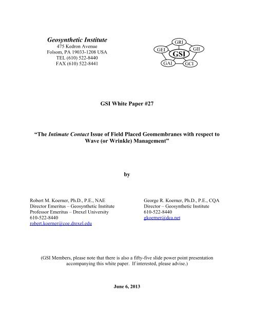
Geosynthetic Institute475 Kedron AvenueFolsom, PA 19033-1208 USATEL (610) 522-8440FAX (610) 522-8441GEIEIGAIGRIGSIGCIGIIGSI White Paper #27“<strong>The</strong> <strong>Intimate</strong> <strong>Contact</strong> <strong>Issue</strong> <strong>of</strong> <strong>Field</strong> <strong>Placed</strong> Geomembranes <strong>with</strong> <strong>respect</strong> <strong>to</strong><strong>Wave</strong> (or Wrinkle) Management”byRobert M. Koerner, Ph.D., P.E., NAEGeorge R. Koerner, Ph.D., P.E., CQADirec<strong>to</strong>r Emeritus – Geosynthetic InstituteDirec<strong>to</strong>r – Geosynthetic InstitutePr<strong>of</strong>essor Emeritus – Drexel University 610-522-8440610-522-8440 gkoerner@dca.netrobert.koerner@coe.drexel.edu(GSI Members, please note that there is also a fifty-five slide power point presentationaccompanying this white paper. If interested, please advise.)June 6, 2013
“<strong>The</strong> <strong>Intimate</strong> <strong>Contact</strong> <strong>Issue</strong> <strong>of</strong> <strong>Field</strong> <strong>Placed</strong> Geomembranes <strong>with</strong> Respect <strong>to</strong> <strong>Wave</strong>(or Winkle) Management”AbstractGSI either directly or through its on-line servicing <strong>of</strong> the Techline (gmatech@ifai.com)receives many questions as <strong>to</strong> deployment <strong>of</strong> geomembranes and, more specifically (<strong>to</strong> the <strong>to</strong>pic<strong>of</strong> this white paper), the fate <strong>of</strong> waves (or wrinkles) in geomembranes when they are backfilledand en<strong>to</strong>mbed by the overlying soil materials. We generally respond by scanning variouspublished papers but now feel it is time <strong>to</strong> summarize the relevant information in the form <strong>of</strong> aGSI White Paper (#27) which is posted on our website and available <strong>to</strong> everyone atwww.geosynthetic-institute.org/whitepaper.htm.After a brief overview and background <strong>of</strong> the situation, we describe a major labora<strong>to</strong>rystudy which was the dissertation <strong>of</strong> Dr. Te-Yang Soong and is very revealing in this regard. <strong>The</strong>major findings <strong>of</strong> that study being (i) that waves as small as 14 mm in height do not flatten outupon the application <strong>of</strong> normal pressure, (ii) that the waves actually collapse forming relativelysharp folds, and (iii) that residual stresses at the folds can be as high as 22% <strong>of</strong> yield where theyare most accentuated. As a result <strong>of</strong> a national survey <strong>of</strong> state regula<strong>to</strong>ry agencies, theimplications <strong>of</strong> en<strong>to</strong>mbed waves are then addressed followed by five methods for achieving“intimate contact” <strong>of</strong> the installed and backfilled geomembranes <strong>to</strong> their subgrade. A summaryand recommendation section is also presented.-1-
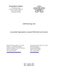
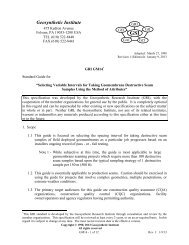
1.0 Overview and BackgroundIt is clear that the concept <strong>of</strong> a composite liner, i.e., a geomembrane placed overcompacted clay liner (<strong>GM</strong>/CCL) or geosynthetic clay liner (<strong>GM</strong>/GCL), in the minds <strong>of</strong>regula<strong>to</strong>rs (and designer’s as well) is <strong>to</strong> achieve a flat geomembrane completely over thesubstrate whatever it may be. That said, it is intuitive that waves or wrinkles will compromisethis situation as the pho<strong>to</strong>graphs <strong>of</strong> Figure 1 attest. <strong>The</strong> generally voiced concerns over buryingor en<strong>to</strong>mbing these waves are the following:Leakage flow through geomembrane holes in<strong>to</strong> the open space beneath the wavePossible shortened life due <strong>to</strong> tensile stress concentrations in the folded geomembranesMini-dam impediment <strong>to</strong> leachate flow along the upper surface <strong>of</strong> the geomembraneDis<strong>to</strong>rtion <strong>of</strong> the underlying CCL or GCL due <strong>to</strong> uneven stresses created by the waveFig. 1 – <strong>Wave</strong>s in exposed geomembranes (GSI pho<strong>to</strong>s).<strong>The</strong> above said, it is well known that the waves are caused by elevated temperatures (incomparison <strong>to</strong> the geomembrane temperatures at placement and seaming) and are fundamentallyrelated <strong>to</strong> the type <strong>of</strong> geomembrane resin as well as its stiffness and thickness. Table 1 presentscoefficients <strong>of</strong> thermal expansion/contraction for common geosynthetic resins. <strong>The</strong> table isfollowed by a numeric example illustrating the amount <strong>of</strong> expansion movement caused by a-2-
temperature increase <strong>of</strong> 30°C which is a typical field situation. <strong>The</strong> calculation is performed forHDPE, LLDPE and PVC geomembranes.Table 1 – Coefficients <strong>of</strong> <strong>The</strong>rmal Expansion/Contraction (various references)Polyethylenehigh densitymedium densitylow densityvery low densityPolypropylenePolyvinyl chlorideunplasticized35% plasticizerPolyamidenylon 6nylon 66PolystyrenePolyesterPolymer Type<strong>The</strong>rmal Linear Expansivity( 10 -5 /C)11-1314-1610-1215-255-95-107-257-97-93-75-9Example: What is the expansion <strong>of</strong> a 5 m long sheet <strong>of</strong> geomembrane due <strong>to</strong> a 30°Cincrease in temperature. Use the table for HDPE, LLDPE and PVC values.Basic Equation:whereSolutions:L = (T)(L)()L = expansion or contraction (+ or -)T = change in temperature (+ or -)L = distance between waves = coefficient <strong>of</strong> thermal expansion/contractionEx. T L L (expansion)(deg. C) (m) (/C) (m) (mm)HDPE 30 5.0 1510 -5 0.022 22LLDPE 30 5.0 1110 -5 0.016 16PVC 30 5.0 1610 -5 0.024 24Note: Due <strong>to</strong> stiffness effects, the HDPE and LLDPE geomembranes result in a singlelarge wave, while the PVC geomembrane results in numerous small waves.-3-
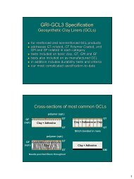
Figure 2a shows such waves (beneath a overlying white protection geotextile) being backfilledby the gravel <strong>of</strong> a landfill’s leachate collection layer. <strong>The</strong>se waves are indeed en<strong>to</strong>mbed by thebackfilled materials and (as will be seen) retain their dis<strong>to</strong>rted shape even after exhuming as thepho<strong>to</strong>graphs <strong>of</strong> Figure 2b indicate.Two Small <strong>Wave</strong>sBeing En<strong>to</strong>mbedOne Large <strong>Wave</strong>Being En<strong>to</strong>mbed(a) <strong>Wave</strong>s being en<strong>to</strong>mbed during backfillingSeveral <strong>Field</strong>Removed <strong>Wave</strong>s in1.5 mm (60 mil)HDPEManyRemoved<strong>Wave</strong>s(b) En<strong>to</strong>mbed waves remaining after excavationFig. 2 – Various field cases <strong>of</strong> poor wave management practice (GSI pho<strong>to</strong>s).It should be mentioned that waves in geomembranes on side slopes generally accumulatedownslope due <strong>to</strong> day-<strong>to</strong>-night thermal cycling such that a final large wave <strong>of</strong>ten occurs at the-4-
<strong>to</strong>e <strong>of</strong> the slope. Furthermore, such waves are <strong>of</strong>ten filled <strong>with</strong> water making the repair throughmultiple geosynthetic layers extremely difficult.2.0 A Major Labora<strong>to</strong>ry <strong>Wave</strong> Study<strong>The</strong> concern over the fate <strong>of</strong> en<strong>to</strong>mbed and backfilled waves prompted a labora<strong>to</strong>ry studysponsored by the U.S. Environmental Protection Agency which formed the dissertation <strong>to</strong>pic <strong>of</strong>Dr. Te-Yang Soong * . <strong>The</strong> study was conducted in both a large wooden box (1.8 1.0 1.0 m)and in small steel boxes (0.3 0.3 0.3 m). <strong>The</strong> large wooden box shown in Figure 3 had a 0.5m wide plexiglass window behind which the geomembrane waves were positioned. An air bagcapable <strong>of</strong> 20 kPa pressure was used for normal pressure <strong>to</strong> observe the actual dis<strong>to</strong>rtion <strong>of</strong> theas-placed wave in the geomembrane over time. It is important <strong>to</strong> note that the ends <strong>of</strong> thegeomembrane were short <strong>of</strong> the box width on both sides by 150 mm. Thus the geomembranewave was free <strong>to</strong> move horizontally as pressure was applied at the surface if it was inclined <strong>to</strong> doso.Fig. 3 – Large wooden box wave test setup.*Soong, T.-Y. and Koerner, R. M. (1998), “Labora<strong>to</strong>ry Study <strong>of</strong> High Density Polyethylene <strong>Wave</strong>s,” Proc. 6 th IGSConf., Atlanta, IFAI Publ., pp. 301-306.*Soong, T.-Y. and Koerner, R. M. (1999), “Behavior <strong>of</strong> <strong>Wave</strong>s in High Density Polyethylene,” Jour. Geotextiles andGeomembranes, Vol. 17, No. 2, pp. 80-104.-5-
<strong>The</strong> results <strong>of</strong> three waves (large, medium and small) are shown in Figure 4.Comment: <strong>Wave</strong>sdon’t go away andthe H/W-valueincreasesFig. 4 – Visual observations <strong>of</strong> large, medium and small waves under increasing pressure.Individual markers were placed on the edges <strong>of</strong> the waves adjacent <strong>to</strong> the plexiglass window sothat the same points could be observed in their movements (notice the small circles on Figure 4sketches). In all cases, the as-placed wave decreased in its void space under the applied pressure<strong>with</strong> the <strong>to</strong>p moving down and the two sides collapsing inward. In terms <strong>of</strong> a wave height-<strong>to</strong>widthratio, the following occurred; large wave, H/W ratio went from 0.5 <strong>to</strong> 2.0,medium wave, H/W ratio went from 0.4 <strong>to</strong> 0.9, and small wave, H/W ratio went from 0.25 <strong>to</strong> 0.4.Most importantly the collapse <strong>of</strong> the waves did not shift the horizontal ends <strong>of</strong> thegeomembranes <strong>to</strong>ward the wooden box walls at all, i.e., the geomembrane ends remained fixed-6-
in their original position. This observation completely contradicts the <strong>of</strong>ten-heard notion thatapplied pressure tends <strong>to</strong> flatten the en<strong>to</strong>mbed waves. This simply does not occur since theincreasing applied normal pressure also increases the friction on the <strong>to</strong>p and bot<strong>to</strong>m horizontalends <strong>of</strong> the geomembrane holding them fixed in position even for these smooth HDPE sheets.More troubling is that the reshaped wave has now tended <strong>to</strong> con<strong>to</strong>rt in<strong>to</strong> much sharper bendssuggesting high stress concentrations.Having these visual findings, emphasis shifted <strong>to</strong> small steel boxes in which normalpressures up <strong>to</strong> 1,100 kPa could safely be applied, see Figure 5a. Furthermore, foil strain gageswere bonded on six locations <strong>of</strong> each <strong>of</strong> the waves and the assembly was then placed in anenvironmental chamber as shown in Figure 5b. <strong>The</strong> experimental design for these boxesconsisted <strong>of</strong> 1000 hour tests <strong>with</strong> varying;normal stresses; from 180 <strong>to</strong> 1100 kPa,original wave heights; from 14 <strong>to</strong> 80 mm,geomembrane thicknesses, from 1.0 <strong>to</strong> 2.5 mm, and testing temperatures; from 23 <strong>to</strong> 55°C<strong>The</strong>se results are shown visually and numerically in Figures 6 a-d, <strong>respect</strong>ively.As pressure increases horizontalportions <strong>of</strong> <strong>GM</strong> remains fixedin position. Pressure above andbelow holds the <strong>GM</strong> endsstationary.(a) Logic and pho<strong>to</strong> small box tests(b) Strain gauge and environmental chamberFig. 5 – Small “strong” box tests and environmental chamber.-7-
(a) Effect <strong>of</strong> normal stress(b) Effect <strong>of</strong> original wave height(c) Effect <strong>of</strong> geomembrane thickness(d) Effect <strong>of</strong> Testing temperatureFig. 6 – Variables evaluated in small steel box tests.(See Soong, et al. 1998, 1999 for details)Finally, the effect <strong>of</strong> dis<strong>to</strong>rted waves on geomembrane stresses were evaluated using data fromthe strain gage readings and is shown in Table 2. <strong>The</strong> data was taken after 10,000 hours for each<strong>of</strong> the four sets <strong>of</strong> variables mentioned. Here is seen that waves as small as 14 mm in height didnot flatten and furthermore that residual stresses were always present. As a percentage <strong>of</strong> yieldstress <strong>of</strong> the geomembrane they were as high as 22% for the 60 mm geomembrane at 42°C.Such implications are not very encouraging <strong>to</strong> say the least!-8-
Table 2 – Residual Stress after 10,000 hours in HDPE geomembrane wavesExperimental Variables and ConditionsResidual Stress(kPa)Residual Stress(% <strong>of</strong> yield)Normal Stress 180 kPa 1200 7.9360 kPa 1300 8.8700 kPa 2000 13.21100 kPa 2100 13.8Original Height <strong>of</strong> <strong>Wave</strong> 14 mm 130 0.820 mm 740 4.940 mm 1500 9.560 mm 2000 13.280 mm 2300 14.9Thickness <strong>of</strong> Geomembrane 1.0 mm 1600 10.31.5 mm 2000 13.22.0 mm 1600 10.62.5 mm 1800 11.5Testing Temperature 23°C 130 0.814 mm - 42°C 250 2.155°C 440 4.523°C 740 4.920 mm - 42°C 850 7.355°C 750 8.023°C 1500 9.540 mm - 42°C 1600 13.755°C 690 7.423°C 2000 13.260 mm - 42°C 2600 22.055°C 1600 17.53.0 Implications <strong>of</strong> En<strong>to</strong>mbed <strong>Wave</strong>sIt is important <strong>to</strong> note that the U.S. EPA in promulgating its original RCRA landfillregulations in the 1980’s fully recognized that for the concept <strong>of</strong> a composite liner <strong>to</strong> functionoptimally the geomembrane had <strong>to</strong> fully reside on the underlying compacted clay liner. <strong>The</strong>ycalled it intimate contact between the two materials. (<strong>The</strong> German BAM regulations are equallydescriptive in that it translates in<strong>to</strong> press-fit). Subsequently, individual states in the USA becamelandfill permit gran<strong>to</strong>rs and developed their individual regulations. A recent survey <strong>of</strong> theseregulations is given in Table 3. Here it can be seen that it is very clear that full contact <strong>of</strong> the-9-
geomembrane <strong>to</strong> the underlying material is either the intent or actually required for achievingintimate contact in composite liners.Table 3 – Survey <strong>of</strong> State Regulations on the <strong>Wave</strong> <strong>Issue</strong>“Direct and Uniform <strong>Contact</strong>”AK, AL, AZ, CO, GA, IA, KS, LA, MT, NC, ND, NE, NJ,NV, OK, PA, SC, SD, TX, UT, VA, VT, WI23 (50%)“<strong>Intimate</strong> <strong>Contact</strong>”HI, ID, MO, MS, NH, OR 6 (13%)“Directly Overlying”CA, FL, IL, MD, MI 5 (11%)“Minimize (or Prevent) <strong>Wave</strong> Occurrence”MN, TN, WA, WY 4 (9%)“Directly Overlain and in <strong>Contact</strong>”NY, RI 2 (4%)Others “uniform and complete” – KY “proper slack” – DE “installed on <strong>to</strong>p <strong>of</strong>” – WV “inspected by qualified CQA” – ME “acceptable <strong>to</strong> direc<strong>to</strong>r” – OH “acceptable <strong>to</strong> manufacturer” - CT6 (13%)46 (100%)Upon numerous discussions <strong>with</strong> regula<strong>to</strong>rs around the world (Germany, United Kingdom,Canada, South Africa, United States, etc.) the concerns over en<strong>to</strong>mbed geomembrane waves arethe following;they violate both the word and intent <strong>of</strong> the large majority <strong>of</strong> regulations,any leakage through the geomembrane wave has a relatively large void area beneath it forflow <strong>to</strong> occur; hence increased leakage is possiblesuch waves imped surface flow thereby creating mini-dams, and-10-
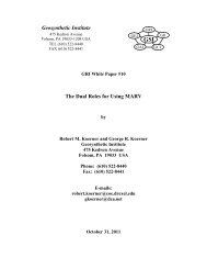
they create stress concentrations and could possibly decrease the geomembrane’slifetime.It is this last point which the authors have as their major concern. GSI has researched andpublished the half-lifetime <strong>of</strong> covered HDPE geomembranes as being approximately 450 years at20°C temperature. * In that study the geomembrane was placed in a completely flat orientationover the subgrade. Had a folded and flattened wave been evaluated, as shown in Figure 2b, thislifetime would most likely have been compromised. Figure 7 shows exhumed PVC and HDPEgeomembranes which had flattened waves in which the high stress concentrations at the apex <strong>of</strong>the fold was precisely where cracking occurred in the PVC and crazing in the HDPE. Clearlytheir lifetimes were shortened in comparison <strong>to</strong> the same geomembranes lying flat <strong>with</strong>outwaves.Cracked PVCGeomembraneFollowing Along<strong>Wave</strong> CrestsCan Cracking in<strong>The</strong>se CrazedHDPE <strong>Wave</strong>sOccur ???(a) Cracking <strong>of</strong> PVC geomembranes(b) Crazing <strong>of</strong> HDPE geomembranesFig. 7 – Exhumed geomembrane waves which exhibited premature problems (GSI Pho<strong>to</strong>s).*See Designing With Geosynthetics, 6 th Ed. (2012), Xlibris Publishing Co., Table 5.12, Page 564.-11-
4.0 Achieving “<strong>Intimate</strong> <strong>Contact</strong>”<strong>The</strong>re have been several formalized attempts at achieving intimate contact <strong>of</strong> ageomembrane <strong>to</strong> its subgrade prior <strong>to</strong> backfilling. At the outset please recognize that none areeasy <strong>to</strong> accomplish nor are they inexpensive. Five different methods will be described.4.1 Push/Accumulate/Cut/Seam – As awkward as this description appears it is ratherstraightforward and commonly practiced. As shown in Figure 8, a lift <strong>of</strong> backfill soil is pushedforward using a bulldozer as the ever increasingly height <strong>of</strong> geosynthetic layers <strong>of</strong> geosyntheticsadvance ahead <strong>of</strong> it. Eventually the wave consisting <strong>of</strong> these layers grow so large that thebackfilling process cannot continue. At this point, the installer’s personnel cut the geosyntheticwaves along their crests (all <strong>of</strong> them since there will <strong>of</strong>ten be multiple layers), fold over theexcess material and then seam them as follows;geomembranes are extrusion fillet welded <strong>to</strong> one another,geonets are overlapped <strong>to</strong> one another and tied using plastic electrical ties,geotextiles are overlapped <strong>to</strong> one another and heat tacked, andGCL’s are simply overlapped on one another.After inspection and/or testing <strong>of</strong> each layer, soil backfilling can resume until the next set <strong>of</strong>waves becomes unwieldy and the process is then repeated.-12-
(a) Nearside fixing berm(b) Farside fixing bermFig. 9 – Fixing berm method <strong>of</strong> installing flat geomembranes <strong>with</strong> no waves(compl. R. Schicketanz).4.3 White (Rather than Black) Geosynthetics – White surfaced geomembranes, either coextendedor laminated, as well as white geotextiles are both useful in minimizing waves. <strong>The</strong> mechanisminvolved comes strictly from temperature reduction <strong>of</strong> the exposed surface. George Koerner * hasperformed such a field study comparing temperature (hence) wave height formation versusgeomembrane temperature for white and black, smooth and textured, HDPE sheets. Each sheetwas 5 m square placed in a checkerboard configuration <strong>with</strong> five thermocouples on each sheetfor average temperature measurements, see Figure 10a. Readings were taken for one-year <strong>with</strong>the seasonal results contrasted <strong>to</strong> ambient temperature as shown in Figure 11. Since wave heightis linearly related <strong>to</strong> temperature these results reflect the situation under consideration. Here isseen a sizeable reduction in temperature for the white versus black geomembranes particularly inthe summer. This, <strong>of</strong> course, is directly reflected in lower wave heights as seen in Figure 11b. Itwas also noted that there is little difference between smooth and textured sheet in this regard.*Koerner, G. R. and Koerner, R. M. (1995), “Temperature, Behavior <strong>of</strong> <strong>Field</strong> Deployed HDPE Geomembranes,” Proc.Geosynthetics ’95 Proc., IFAI, Roseville, MN, pp. 921-937.-14-
(a) <strong>Field</strong> temperature study(Koerner and Koerner, 1995)(b) Co-extrusion white surfaced sheet(compl. GSE Lining Technology LLC)Fig. 10 – Examples <strong>of</strong> white surfaced geomembranes <strong>to</strong> reduce temperature, hence wave heights.-15-
Fig. 11 – Results <strong>of</strong> temperature investigation <strong>of</strong> exposed geomembranes; Koerner and Koerner 1995).-16-
4.4 Temporary Tent Moving Over Placement Area – On several occasions installers have used atemporary tent over the geomembrane placement and backfilling area. This can cover a singleunrolled panel, as in Figure 12a, or over a much larger area as in Figure 12b. Obviously,ultraviolet light is avoided and temperatures can be somewhat reduced but backfilling underthese conditions is difficult and must be done <strong>with</strong> great care. Additionally, the tent itself mustbe secured sufficiently so as <strong>to</strong> avoid wind uplift and subsequent damage.(a) Single roll panel size(b) Multiple roll panel sizeFig. 12 – Temporary tent moving over placement area (compl. R. Schicketanz).4.5 Working With Nature – It can be easily observed that the waves shown in Figure 1 are attheir height in the noonday sun or shortly thereafter. Furthermore, they dissipate rapidly as thetemperature decreases and ultraviolet light is avoided during the night. This can be seen inFigure 13 and is common <strong>to</strong> all sites. It then begs-the-question as <strong>to</strong> requiring that backfillingshould be limited <strong>to</strong> night work extending only in<strong>to</strong> the early morning hours. In this regard it issimply working <strong>with</strong> nature.-17-
That said, there are distinct disadvantages <strong>to</strong> night work in that temporary lights must beprovided, worker efficiency is compromised, worker safety must be assured, and the workschedule for all involved (installer, contrac<strong>to</strong>r, inspec<strong>to</strong>r, regula<strong>to</strong>r and others) must becoordinated and this is <strong>of</strong>ten unwieldy <strong>to</strong> accomplish.Liner at 2:00 PM in AfternoonLiner at 7:00 AM in MorningLiner at 9:00 AM in MorningFig. 13 – Working <strong>with</strong> nature <strong>to</strong> achieve wave-free geomembranes (GSI pho<strong>to</strong>s).-18-
5.0 Summary and RecommendationsThis rather lengthy white paper is framed around a <strong>to</strong>pic called by many as “wave (orwrinkle) management” <strong>of</strong> field deployed and backfilled geomembranes. It is prompted becausethe composite action <strong>of</strong> a geomembrane over a low permeability soil (CCL, GCL, other) isoptimized when the geomembrane is flat <strong>with</strong> no en<strong>to</strong>mbed waves or wrinkles. From aregula<strong>to</strong>ry perspective it is necessary <strong>to</strong> achieve intimate contact or equivalent wording.To examine the technical aspects <strong>of</strong> the situation, a major labora<strong>to</strong>ry study was conductedindicating that waves as small as 14 mm in height when backfilled and en<strong>to</strong>mbed simply do notflatten. In fact, the larger waves squash under applied normal pressure and can form sharpbends. <strong>The</strong> residual stresses in the <strong>to</strong>pmost 180° bend <strong>of</strong> the flattened waves were measured <strong>to</strong>be as high as 22% <strong>of</strong> yield strength for HDPE. Exhumed folded waves have even cracked orcrazed along these 180° folded waves (recall Figure 7).Other implications <strong>of</strong> en<strong>to</strong>mbed folded waves are increased area <strong>of</strong> seepage when holesare in the geomembrane wave, dis<strong>to</strong>rtion <strong>of</strong> the subgrade (particularly CCL’s) due <strong>to</strong> unevenground pressure (the pressure is zero beneath the wave) and an interrupted flow surface on the<strong>to</strong>p <strong>of</strong> the geomembrane due <strong>to</strong> the waves and their random orientation.This summary leads <strong>to</strong> the recommendation that waves should not exist duringbackfilling in order that intimate contact is achieved. To do so, however, is not easy orinexpensive. <strong>The</strong> white paper <strong>of</strong>fered five methods so as <strong>to</strong> avoid en<strong>to</strong>mbed waves. Table 4provides summary comments in this regard.-19-
Table 4 – Methods for Achieving “<strong>Intimate</strong> <strong>Contact</strong>”Method Advantages Disadvantages4.1 push/accumulate/cut/seam4.2 fixing berms or piles4.3 white sheet or white geotextile4.4 temporary tent4.5 backfill during night or in morningquick and cheaphelps greatlyquick and easyhelps somewhatworking <strong>with</strong> natureextrusion welds; inspectionslow and expensivesmaller waves still presentlow productivity; high costlimits productivity; safetyIn closing, it appears <strong>to</strong> the authors that the necessary coordination in facilitating a nowavestrategy is between the geosynthetics installer working in tandem <strong>with</strong> the earthworkcontrac<strong>to</strong>r. <strong>The</strong>y must closely facilitate any strategy listed in Table 4 so as <strong>to</strong> obtain the desiredresult. Furthermore, all strategies will cost more (even much more) than simply burying anden<strong>to</strong>mbing the waves during backfilling as has <strong>of</strong>ten been done in the past.Critically important in construction bidding is specifically what is stated, or not stated,about the situation in pre-bid documents. If no waves are allowed <strong>to</strong> be backfilled and en<strong>to</strong>mbedin the project permit, the installer/contrac<strong>to</strong>r team must be aware <strong>of</strong> the situation before biddingsince increased installation costs are significant. At a German/USA joint workshop * is wasestimated that both the fixing berm method and the temporary tent method were approximatelyten-times the installation cost <strong>of</strong> not being concerned about en<strong>to</strong>mbed waves. Thus, at the heart<strong>of</strong> a transition <strong>to</strong> a no-en<strong>to</strong>mbed wave strategy is a regula<strong>to</strong>ry requirement followed by anunequivocal statement in the construction quality assurance document for the field inspec<strong>to</strong>rs t<strong>of</strong>ollow. In the end, however, a “no wave” strategy will result in a greatly improvedenvironmentally safe and secure liner system.*Corbet, S. P. and Peters, M. (1996), “First Germany/USA Geomembrane Workshop,” Geotextiles andGeomembranes, Vol. 14, No. 12, pp. 647-726.-20-