Geosynthetic Opportunities Associated With Shale ... - Geosynthetica
Geosynthetic Opportunities Associated With Shale ... - Geosynthetica
Geosynthetic Opportunities Associated With Shale ... - Geosynthetica

Create successful ePaper yourself
Turn your PDF publications into a flip-book with our unique Google optimized e-Paper software.
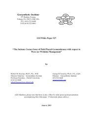
<strong>Geosynthetic</strong> Institute475 Kedron AvenueFolsom, PA 19033-1208 USATEL (610) 522-8440FAX (610) 522-8441GEIGRIGSIGAI GCIGIIGRI White Paper #20<strong>Geosynthetic</strong> <strong>Opportunities</strong> <strong>Associated</strong> <strong>With</strong> <strong>Shale</strong> Gas ExtractionRobert M. Koerner, Ph.D., P.E., NAEGeorge R. Koerner, Ph.D., P.E., CQADirector – <strong>Geosynthetic</strong> InstituteDirector DesignateEmeritus Professor – Drexel University <strong>Geosynthetic</strong> InstitutePhone: 610-522-8440 Phone: 610-522-8440Fax: 610-522-8441 Fax: 610-522-8441robert.koerner@coe.drexel.edugkoerner@dca.netOrig: August 2, 2011Rev: August 8, 2011
<strong>Geosynthetic</strong> <strong>Opportunities</strong> <strong>Associated</strong> <strong>With</strong> <strong>Shale</strong> Gas ExtractionAbstractWhile natural gas contained within shale rock is geologic by its very nature, the practiceof its removal by horizontal drilling coupled with hydrofracing is quite recent. Indeed, thesedual technologies are making possible the recovery of huge amounts of natural gas. So much sothat one can envision natural gas as an energy source rivaling oil, coal and nuclear, whiledwarfing all of the renewables combined. The potential in this regard is awesome particularlysince it is worldwide in its availability and opportunities.This white paper briefly describes shale gas drilling and extraction operations, along withits associated environmental concerns. Using this as a background, the paper then describes andillustrates many geosynthetic materials opportunities that exist in order to make the overalloperations more efficient, economical, and environmentally acceptable.<strong>Shale</strong> Gas Plays *<strong>Shale</strong> is a fine-grained sedimentary rock which is formed by heat and pressure overgeologic time. Many formations contain organic materials (they are then called oil shales),which upon decay, generates natural gas within the rock itself. The liberation, capture andtransmission of this gas is at the heart of the technology. It should be mentioned that natural gashas traditionally accompanied oil drilling operations and has historically been a nuisance to oildrillers.However, this same gas now takes “center stage” insofar as this white paper isconcerned.<strong>Shale</strong> gas plays are both nationwide and worldwide in their occurrence, e.g., see Figure 1in which the data is in units of trillions of cubic meters. In the U.S., there is activity in manystates as Figure 2 indicates. Of the locations shown, the Barnett formation in the Fort Worth* The word “plays” is customarily used when describing the exploration, drilling, hydrofracturing and recovery ofnatural gas as described herein.-1-
asin is very significant since it was the first large-scale operation using these newer drilling andextraction technologies. By 2004, it had been explored by 15,000 deep wells, over 4000 in 2007alone, and had produced 1.4 trillion cubic feet; TCF (0.04 trillion cubic meters, TCM) of naturalgas in 2008. It appears as though horizontal drilling at great depths coupled with hydraulicfracturing was perfected in the Barnett shale of Texas.Figure 1 – Worldwide conventional and shale gas reserves (The Economist, August 6, 2011).Figure 2 – United States shale gas plays (compl. Wikipedia).-2-
The most recent major gas play is in the Marcellus formation underlying major parts ofPennsylvania, New York, Ohio and West Virginia. Figure 3 shows the extent and depth of thisformation, in which it is seen to be near surface in Ohio, but 7000 ft (2100 m) deep inPennsylvania and New York. The Marcellus formation is about 800 ft. (40 m) thick in these twostates and only 50 feet (15 m) thick in Ohio. Pennsylvania is currently in full production ofnatural gas with 2815 producing wells and 3300 permits granted in 2010 (up from 117 in 2007).Meanwhile, New York has a temporary moratorium on gas drilling pending legislative actionexpected in the near future.Figure 3 – Plan and elevation views of Marcellus <strong>Shale</strong> (compl. Wikipedia).-3-
The Marcellus formation is a 400 M year old marine sedimentary rock named for anoutcrop near Marcellus, New York. The bedding is well developed and it is relatively easy tofracture. That said, at these depths it requires approximately 15,000 lb/sq. in. (103 MPa) toaccomplish the fracturing. The in-situ and surface exposed features are apparent in Figure 4. Itsorganic content varies from 1 to 10% and it sometimes contains enough carbon to supportcombustion. The Marcellus is underlain by the Utica formation which is a much more extensiveformation covering all of New York State and continues into Canada. To our knowledge theUtica formation is not being developed at this time nor are the overlying formations, the UpperDevonian shales. However, both of these formations are thought to have large potential gasplays.Figure 4 – In situ and fractured Marcellus shale (compl. Wikipedia).The U. S. Department of Energy estimates that the Marcellus contains 262 trillion cubicfeet, or TCF (7.4 trillion cubic meters, or TCM) of natural gas. Conversely, Professor TerryEngelder of Penn State University estimates are much higher, i.e., 4,360 TCF (123 TCM) total ofwhich 1,310 TCF (37 TCM) are recoverable. At a market price of $0.02/ft 3 ($0.71/m 3 ) the U.S.-4-
DOE estimated value is $5.2T, while Engelder’s is $26.2T. Whatever estimate holds true, thefinancial incentives are enormous. For example, Professor Timothy Considine of the Universityof Wyoming estimates that a typical Marcellus well generates $2.8 M in direct economicbenefits, another $1.5 M from workers and landowners, and $2.0 M in federal, state and localtaxes. This type of financial incentive is, of course, reflected in the present activity associatedwith shale gas extraction, transportation and eventual usage as an energy source.Regulations and Environmental ConcernsThe U.S. Energy Policy Act of 2005 was, and is, the foremost federal regulatory actgoverning shale gas plays of the type described in this white paper. Two aspects of thislegislation have attracted considerable scrutiny;(i)(ii)hydrofracking was exempted from the Safe Drinking Water Act, andchemical additives to the water used for fracing were exempted from disclosure.To gain some perspective in this regard a chemical analysis of the flowback fracwater (at aspecific site) is of interest, see Table 1. Note should be made of the highlighted alkalineminerals which results in an extremely brackish liquid about five-times the salinity of sea water.Also to be noted is the number of heavy metals, although the quantities are felt to be relativelylow.Table 1 –Chemical Analysis of Flowback Water at a site near Williamsport, Pennsylvania(compl. CETCO)Na, mg/Kg 25,930 Mg, mg/Kg 725 Ag, mg/Kg 12K, mg/Kg 137 CL, mg/Kg 60,769 Au, mg/Kg 23Ca, mg/Kg 6,896 HCO 3 , mg/Kg 275 Ba, mg/Kg 5,145Fe, mg/Kg 39 Hg, mg/L
It should be noted that pending federal legislation, the so-called Frac Act of 2009, will requiredisclosure of fracing chemicals and place the entire process under U.S. Environmental ProtectionAgency regulations.At the state-level in Pennsylvania, shale gas operations are regulated under variousdepartments, for example;drilling via the state Oil & Gas Division,fracing water via the state Field & Stream Division, andwaste disposal via the state Solid Waste Division.In keeping with an emotionally-charged technology, such as natural gas plays, there aremany environmental issues that have been raised by various concerned organizations, such as,federal, state and local regulatory groups, local water authorities, various industry groups,concerned citizens groups, etc. Some (but clearly not all) are mentioned below and have beenselected because of the positive potential of using geosynthetic materials to solve, or at leastmitigate, the issues listed:Containment and storage of large quantities of surface water for drilling and fracturingpurposes.Storage and reuse of flow-back water from the hydrofracing process.Proper disposal of the “cuttings” from drilling operations (ca. 1000 tons per well).Drill pad site contamination (each being typically 3-5 acres in size).Frac-tank and storage area contamination.Access roads, parking and staging areas, and maintenance thereof.Minimizing site disturbance and providing level staging and working areas.Soil erosion and temporary containment so as to avoid stream and propertycontamination.-6-
In order to appreciate some of these environmental issues it is helpful to view a compositedrilling operation as well as the enormity of the drilling wells themselves, see Figures 5a and 5b.Furthermore, some knowledge of the actual drilling operations are significant insofar assite development and maintenance. For example, a typical well site usually contains a number ofvertical wells (3 to 6) which have horizontal branches going in different directions. Also, eachwell is generally hydraulically fractured several times. This iterative process depends upon thediminishing gas yield over time. Lastly, it is anticipated that a well pad should have a usablelifetime of approximately 20 to 30 years.Furthermore, the following generalized goals with these shale gas extraction plays areinteresting to keep in mind as we now go into geosynthetic opportunities and solutions;the drilling operations are large construction projects with considerable public andregulatory scrutiny,once permitted, fast mobilization and deployment is necessary,a “low profile” is advantageous particularly with minimization of truck traffic, andbenefit/cost is always important but maximum benefit often outweighs minimum cost.-7-
(a) Typical gas extraction operation in Marcellus <strong>Shale</strong> in Pennsylvania(b) Several large gas well drill rigsFigure 5 –Site operations at natural gas plays (compl. Wikipedia).-8-
<strong>Geosynthetic</strong> <strong>Opportunities</strong>This section of the White Paper describes some of the many geosynthetic solutions thatcan be applied to shale gas plays. The section is subdivided according to (i) the drillingoperations themselves, (ii) opportunities at permanent locations, and (iii) opportunities attemporary locations.<strong>Geosynthetic</strong>s <strong>Associated</strong> with Drilling OperationsThe first, and quite obvious, opportunity is the use of geomembranes for fresh watercontainment and subsequent use in the well drilling operations. The design stages are wellknown and consist of the following sequential steps:geometry (length, width, depth)cross section materialsgeomembrane typegeomembrane thicknesssubgrade soil stabilitycover soil stabilityrunout and anchor trench detailsPerhaps the most overlooked design detail is the requirement of providing an underdrain systembeneath the geomembrane. Shown in Figure 6 are the all-to-common “whales” lifting up thegeomembrane via rising gases within the underlying soil subgrade. Various underdrain solutionsthat should be considered are the following:thick needlepunched nonwoven geotextilesdrainage geocomposites (complete or strips)interconnected perforated pipe systemgeotextiles with small perforated pipessand bedding layer (with pipe network)-9-
Figure 6 – Some very recent whales (2009) in a potable water reservoir (compl. GSI).The second, and also obvious, opportunity is the containment and re-use of the flow backwater which was characterized in Table 1 and is seen to be quite contaminated. Presently, thiswater is generally being held in mobile holding tanks (see Figure 7) but geomembrane linedponds or even underground storage systems offer attractive alternatives. Figure 8 is a doublelined contaminated surface impoundment in Virginia (the cross-section is soil subgrade,geotextile, geomembrane, geonet, geomembrane from bottom to top) and Figure 9 is anunderground storage system that is typically used for storm water runoff from industrial andprivate development sites. Both strategies should be considered in contrast to hundreds ofholding tanks interconnected to one another as shown in Figure 7.Figure 7 – Mobile holding tanks for frac-water (compl. Wikipedia).-10-
Figure 8 – Double-lined surface impoundment for contaminated water (compl. GSI).-11-
Figure 9 – Various underground storm water storage systems (compl. Rainstore®).-12-
A third opportunity for geosynthetics is the containment of cuttings from the drillingoperation itself insofar as proper safe and secure disposal is concerned. In this regard, it shouldbe mentioned that each well produces about 1000 tons (~ 75 truckloads) of contaminated cuttingsof the type shown in Figure 10.cuttingsFigure 10 – Contaminated cuttings from well drilling (compl. Wikipedia).These cuttings can, of course, go to a licensed public or private landfill but alternatively can beplaced in geotextile tubes at the site (or within a landfill as seen in Figure 11) and can even havea decontaminant added such that the treated effluent can be released to the environment. Theaddition of charcoal, activated carbon, phosphoric rock, or organoclays is necessary and all arewithin decontamination technology that is associated with geotextile tubes.-13-
Figure 11 – Geotextile tubes located within a landfill as they are being filled whereby theeffluent is automatically captured (compl. GSI).<strong>Opportunities</strong> at Permanent LocationsOf first priority in this category are the roadways into and out of the drilling site whichare necessary for the 20 to 30 years lifetime of the operations. Geotextiles and geogrids havebeen shown to save from 10 to 50% of the crushed stone thickness of base courses placed on soilsubgrades * . The functions of separation, stabilization and/or replacement are clearly indicated inthe literature since this application has been ongoing for about 30-years; see Figure 12. Not onlyis there a savings in stone base material, the distance from the quarry is significant in the totalcost of the application.A second way of reducing crushed stone thickness there is considerable economy offeredby using geocells as shown in Figure 13. They are filled with gravel, sand or locally availablesoil and their design (which uses a geotextile beneath them) is well established. Thicknessessaved are from 50 to 100% over the use of gravel by itself.* The old adage that “Ten pounds of soil and ten pounds of water make twenty pounds of mud” is seen at many drillsites particularly in the spring of the year.-14-
Figure 12 – Use of a geotextile (or geogrid) in an unpaved road applications(compl. IFAI/GMA).-15-
Figure 13 – Thick (~ 8.0 in or 200 mm) geocells (compl. PRS Med. Ltd.).Thirdly, these same geocells in a less-thick format are ideal for parking and staging areaslocated adjacent to the drill pad, see Figure 14.Fourth, locally available soils (even silts and clays) can be meaningfully strengthened bythe addition of discrete fibers or microgrids, see Figure 15. Both types lead to major increases inshear strength in the upper 4 to 12 inches (100 to 300 mm) of surface. The technology is welladvanced and mature at this point in time.-16-
Figure 14 – Less thick (~ 4 in or 100 mm) geocells (compl. CETCO Cont. Services).Figure 15 – Examples of discrete fibers and microgrids (compl. Propex and Tensar).Fifth, the drill pad site along with adjacent parking and staging areas must be level. Toaccomplish this in hilly terrain (as is typical in the Marcellus shale area) one needs to createstable soil slopes or even vertical walls. The concept of mechanically stabilized earth (MSE)slopes and walls using geogrid or geotxtile reinforcement is ideal in this regard. Not only arethese situations the least expensive of all types of retaining structures (GRI Report #20), they arestraightforward to construct, have no limitations as to curvature, height, or orientation, and haveproven stable insofar as extreme surcharge loads are concerned; see Figure 16.-17-
Figure 16 – Vegetated MSE wall in Pennsylvania (compl. Waste Management, Inc.)-18-
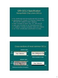
Sixth, the drill pad itself should be lined so as to avoid contamination from spilledfracwater, hydrocarbons or other potential ground contaminates. This calls for a geomembrane,a geosynthetic clay liner, or both, as a composite liner. There are many choices in this regardand a designer should consider the generation of a benefit/cost ratio to select the appropriate linermaterial. See Table 2 for a hypothetical example situation. In it, the procedural steps are asfollows:(a) select relevant site-specific properties as per application(b) weight properties from 10 (high) to 1 (low)(c) select candidate geomembrane types(d) grade types from 5 (high) and 1 (low)(e) multiply weight by grade(f) add resulting numbers(g) divide by estimated unit costs(h) select the geomembrane type with highest benefit/cost ratioUpon geomembrane selection, the engineer must now specify the properties. For the pastseveral years there have been generic specifications available for common liner materials. Thosethat are currently available are the following:GRI-GM13 for high density polyethylene (HDPE)GRI-GM17 for linear low density polyethylene (LLDPE)GRI-GM18 for flexible polypropylene(fPP and fPP-R)GRI-GM21 for ethylene propylene diene terpolymer (EPDM and EPDM-R)GRI-GM25 for reinforced linear low density polyethylene (LLDPE-R)GRI-GCL3 for geosynthetic clay liners (GCL)ASTM-D7176 for polyvinyl chloride (PVC)-19-
Hypothetical Example OnlyTable 2 – Example B/C Matrix for Drill Pond Liner GeomembraneProperty Weighting HDPE LLDPE fPP-R PVC CSPE-R EPDM-Rchem. resist. 3 5 15 3 9 4 12 2 6 5 15 5 15durability 10 5 50 3 30 4 40 2 20 5 50 5 50UV stab. 8 5 40 3 24 4 32 2 16 5 40 5 40shear strength 7 4 28 4 28 3 21 3 21 3 21 3 21stress. crack 7 2 14 5 35 5 35 5 35 5 35 5 35seamability 9 4 36 3 27 3 27 4 36 3 27 2 18seam behavior 9 4 36 4 36 3 27 4 36 3 27 3 27strength 5 4 20 3 15 5 25 3 15 5 25 5 25elongation 5 4 20 5 25 2 10 5 25 2 10 2 10tear 6 3 18 2 12 5 30 2 12 5 30 5 30puncture 6 4 24 3 18 5 30 3 18 5 30 5 30impact 6 4 24 3 18 4 24 3 18 4 24 4 24exp./cont. 4 2 8 3 12 4 16 3 12 4 16 4 16constructability 10 3 30 4 40 4 40 5 50 4 40 4 40benefit n/a - 363 - 329 - 369 - 320 - 390 - 381cost/m 2 n/a - 10.00 - 10.50 - 11.25 - 9.00 - 12.50 - 13.00B/C ratio n/a - 36.3 - 31.3 - 32.8 - 35.5 - 31.2 - 29.3-20-
Seventh, natural gas plays are replete with plastic pipe. Such pipe as shown in Figure 17is used for many purposes such as;fresh water transmissionfrac water transmissiongas transmissionsurface water drainageFigure 17 – HDPE solid wall, PVC solid wall, and HPDE corrugated pipe (various sources).-21-
The pipe is generally HDPE or PVC and can be solid wall (for transmission) or corrugated withslots or holes (for drainage). Whatever the case, natural gas plays require the use of plastic pipein a major way.<strong>Opportunities</strong> at Temporary LocationsFirst of all, temporary roadways of weeks or months are necessary in connection withsetup and eventual demobilization at natural gas plays. The geosynthetics industry has thecapability of providing wearing surfaces placed directly on the ground. Shown in Figure 18 arelight and heavy roadway systems developed by the Dutch Military for rapid deployment of heavyvehicles and equipment. They are typically 60 ft. long and 10 ft. wide and the weight varies withtype. Obviously, they can be redeployed as often as necessary.Secondly, temporary dams may be used for surface water control or for accidental spillsassociated with the drilling or containment operations. Figure 19 shows that geomembranes canreadily provide such temporary containment and be adaptable to myriad applications.Third, on sloping surfaces soil erosion is a concern and must be avoided so as to preventsilting of off-site areas and local streams and rivers. Geotextile silt fences have played aneconomical role in this regard for decades. Figure 20 shows such a silt fence being installed andproperly functioning.Fourth, rather than containing the site’s erosion after it occurs it is better to control andstabilize it before it starts. This has been traditionally provided by geosynthetic-erosion controlmaterials of which there are a great variety. The two major categories are shown in Figure 21 forslopes and channels/ditches, respectively. Designs are well advanced in both cases.-22-
(a) Light trackway type(b) Heavy trackway typeFigure 18- Temporary roadways developed by the Dutch military.-23-
Figure 19 – Temporary containment systems (compl. Portadam®).(a) Silt fence installation (compl. IFAI)(b) Properly perofrming silt fence (compl. GSI)Figure 20 – Silt fence for erosion control.-24-
(a) Slope erosion control (compl. TenCate)(b) Channel/ditch erosion control (compl. Colbond)Figure 21 – Erosion control and revegetation systems.-25-
Closing CommentsNatural gas plays (including actual drilling, the well pad, staging and parking areas,permanent and temporary roadways and access areas) are extremely large construction projectswith enormous natural gas energy potential. They also have attracted considerable public andregulatory scrutiny. That said, once permits are obtained, fast mobilization, deployment andoperations are necessary. <strong>With</strong>in the entire activity a low profile and exposure is always anadvantage. All of these aspects can capitalize on geosynthetics in a major way. This WhitePaper has described many of these opportunities.Of course, and within acceptable environmental criteria, benefit/cost analyses are alwaysrequired for alternative and competing systems. We feel that in so doing, geosynthetic materialswill invariably be the obvious choice for many of these applications.For general information on geosynthetics see the following websites or contact theauthors of this White Paper.<strong>Geosynthetic</strong> Institute www.geosynthetic-institute.org<strong>Geosynthetic</strong> Materials Association www.ifai.comGMA Techline at gmatechline@ifai.com<strong>Geosynthetic</strong>s Magazine www.geosyntheticsmagazine.com<strong>Geosynthetic</strong>a www.geosynthetica.netInternational <strong>Geosynthetic</strong>s Society www.geosyntheticssociety.orgNorth American <strong>Geosynthetic</strong>s Society www.nagsigs.org-26-