Selection of Copper vs. Aluminum Rotors for Induction ... - Siemens
Selection of Copper vs. Aluminum Rotors for Induction ... - Siemens
Selection of Copper vs. Aluminum Rotors for Induction ... - Siemens

Create successful ePaper yourself
Turn your PDF publications into a flip-book with our unique Google optimized e-Paper software.
2) Hold punchings and end connector clamp assembly<br />
together.<br />
3) Insert shaft into hot core.<br />
4) Insert bars.<br />
5) Machine end <strong>of</strong> bars.<br />
6) Weld end connector to bars.<br />
7) Turn and balance rotor assembly.<br />
Some <strong>of</strong> the key points to assure that the highest quality &<br />
reliability is obtained when manufacturing AlBar rotors is:<br />
• Consistent & controlled clamp pressure – see CuBar<br />
section <strong>for</strong> additional explanation.<br />
• The rotor bars should be shimmed and center swaged<br />
or locked in such a way the bars don’t ratchet themselves out<br />
<strong>of</strong> the core – see CuBar section <strong>for</strong> additional explanation.<br />
• Welding directly on the shaft should be minimized. Any<br />
welding will result in residual stresses and potential thermal<br />
instability.<br />
• Proper core and bar temperature to avoid excessively<br />
high residual stresses when core cools.<br />
Fabricated <strong>Copper</strong> Bar Construction (CuBar):<br />
CuBar construction is the oldest, dating back to the 1920’s.<br />
Although it is possible to manufacture CuBar rotors in any<br />
size, economics will make this choice unattractive <strong>for</strong> small<br />
motors.<br />
The fabricated copper bar rotor is constructed utilizing the<br />
following steps:<br />
1) Stack rotor punchings on a stacking mandrel.<br />
2) Hold punchings together along with end heads. Clamp<br />
assembly together<br />
3) Insert shaft into hot core, lock core in place without<br />
welding.<br />
4) Insert bars.<br />
5) Machine end <strong>of</strong> bars.<br />
6) Braze end connectors to bars.<br />
7) Turn and balance rotor assembly.<br />
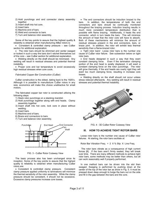
Punchings End Head<br />
FIG. 3 - CuBar Rotor Cutaway View<br />
End Connector<br />
Fan<br />
Shaft<br />
The basic process also has been unchanged since its<br />
inception. Some <strong>of</strong> the key points to assure that the highest<br />
quality & reliability is obtained when manufacturing CuBar<br />
rotors are:<br />
• Consistent & controlled clamp pressure. Consistent<br />
clamp pressure applied uni<strong>for</strong>mly to laminations will minimize<br />
the thermal sensitivity <strong>of</strong> the rotor assembly. While the clamp<br />
pressure should be consistent, it should not be excessive.<br />
Excessive clamp pressures increase core losses.<br />
Page 3 <strong>of</strong> 11<br />
• The end connectors should be induction brazed to the<br />
bars. In addition, the temperatures <strong>of</strong> both the end<br />
connectors and bars should be continually monitored<br />
throughout the brazing process. <strong>Induction</strong> brazing results in<br />
much more consistent temperature distribution than is<br />
possible with flame brazing. Additionally, it heats the end<br />
connector, which in turn heats the bars. This will minimize<br />
the amount <strong>of</strong> heat that the rotor core will have to absorb.<br />
Both <strong>of</strong> these mechanisms will minimize the amount <strong>of</strong><br />
residual stresses present in the end connectors, bars, or<br />
braze joint. In addition, the rotor will exhibit less thermal<br />
sensitivity than a flame-brazed rotor.<br />
• Tight rotor bars! Loose rotor bars is the number one<br />
cause <strong>of</strong> CuBar rotor failure. See subsection below on tight<br />
rotor bars.<br />
• End heads designed in such a way that they exert<br />
constant clamping <strong>for</strong>ce. Even if the lamination clamping<br />
portion <strong>of</strong> the end head is axially displaced, it will exert a<br />
constant clamping <strong>for</strong>ce on the rotor punchings. The rotor<br />
will grow thermally, if the end heads are overly rigid they will<br />
exert too much clamping <strong>for</strong>ce, resulting in increase core<br />
losses.<br />
• Welding directly on the shaft should not occur unless<br />
stress relieved afterwards. Any welding will result in residual<br />
stresses and potential thermal instability.<br />
FIG. 4 - 3D CuBar Rotor Cutaway View<br />
III. HOW TO ACHIEVE TIGHT ROTOR BARS<br />
Loose rotor bars is the number one cause <strong>of</strong> CuBar rotor<br />
failures. At starting, the rotor bars oscillate at:<br />
Rotor Bar Vibration Freq. = 2 X % Slip X Line Freq.<br />
The rotor bars vibrate as a consequence <strong>of</strong> high current<br />
<strong>for</strong>ces [6]. If the bars aren’t firmly seated, they will break<br />
over time. There are many different methods to achieve tight<br />
rotor bars, some methods may be better than others, but all<br />
can work reasonably well if properly per<strong>for</strong>med.<br />
In one method bars can be driven into the slot then<br />
swaged. Swaging is per<strong>for</strong>med by pushing down at the<br />
center <strong>of</strong> the top <strong>of</strong> the rotor bar as show in Fig. 5. It must be<br />
pressed down deep enough to bulge the bars out on the side<br />
and fill in the gap between the bars and the core.