Selection of Copper vs. Aluminum Rotors for Induction ... - Siemens
Selection of Copper vs. Aluminum Rotors for Induction ... - Siemens
Selection of Copper vs. Aluminum Rotors for Induction ... - Siemens

You also want an ePaper? Increase the reach of your titles
YUMPU automatically turns print PDFs into web optimized ePapers that Google loves.
speed. These high strength end retaining rings can be used<br />
on aluminum or copper end connectors.<br />
High strength retaining rings are placed on the outer<br />
diameter <strong>of</strong> the end connector. There is an interference fit<br />
while the rotor is at rest. This interference fit results in an<br />
initial compressive stress on the end connector, and a tensile<br />
hoop stress on the retaining ring. As the rotor is brought up<br />
to speed, the centrifugal <strong>for</strong>ce causes the retaining ring to<br />
lose some <strong>of</strong> its initial interference. In the process, the<br />
retaining ring tensile stress increases. At the same time, the<br />
initial compressive stress on the end connector becomes less<br />
compressive, and as the rotor speed increases trans<strong>for</strong>ms<br />
into a tensile hoop stress. At full speed, the tensile hoop<br />
stress <strong>of</strong> the end connector is less than what it would have<br />
been without the retaining ring. For comparative purposes<br />
review the table <strong>for</strong> the strengths <strong>of</strong> the various materials<br />
used in rotor construction [10].<br />
In the above table the strengths are in KSI (PSI/1000). It<br />
should be noted that the strength <strong>of</strong> copper is at a .5% <strong>of</strong>fset,<br />
and not the .2% <strong>of</strong>fset that is normally used <strong>for</strong> metal<br />
strength determination.<br />
Residual Stresses:<br />
Yield Tensile<br />
<strong>Aluminum</strong> 4 10<br />
<strong>Copper</strong> * 10 32<br />
Alum-Bronze 60 110<br />
A286 Stainless 100 146<br />
Residual stresses arise as a result <strong>of</strong> the manufacturing<br />
process. In general, in all <strong>of</strong> the construction methods<br />
utilized, the initial stresses will be higher than yield strength<br />
<strong>of</strong> the material. For example, when a ADC rotor is die cast,<br />
the aluminum will start solidifying at 1200 o F. The coefficient<br />
<strong>of</strong> thermal expansion <strong>of</strong> aluminum is 100% greater than that<br />
<strong>of</strong> steel. As the rotor cools to ambient temperature, a <strong>for</strong>ce is<br />
exerted on the iron stack by the shrinking aluminum bars<br />
(which have already froze). The <strong>for</strong>ce is great enough to<br />
cause the aluminum bars to yield. Residual stress in the<br />
copper construction is somewhat different. Since the end<br />
rings are not up against the core when brazed, axial stresses<br />
do not exist. However, bending stresses due to end ring<br />
thermal expansion still do exist. When the end connector is<br />
brazed to the rotor bars, the end connector is heated to over<br />
800 o F, which causes it to expand radially. The core<br />
temperature is slightly elevated, but nowhere close to 800 o F.<br />
On one end, the bars are constrained from moving by the<br />
core, and at the other end the bars are <strong>for</strong>ced to move with<br />
the end connector. The bars are thus put in a bending mode<br />
and shear mode, resulting in initial stresses that exceed the<br />
bars/end connectors yield strength. Although high residual<br />
stresses exist, rotors have been successfully built <strong>for</strong> many<br />
years utilizing these construction techniques.<br />
V. FUNDAMENTALS OF INDUCTION MOTOR<br />
OPERATION<br />
To properly select the optimal rotor construction method, it<br />
is important to understand how a “squirrel cage rotor” in an<br />
Page 5 <strong>of</strong> 11<br />
induction motor works. Additionally, an understanding <strong>of</strong> how<br />
different per<strong>for</strong>mance characteristics can be achieved by<br />
altering the rotor design is necessary. It is not intended here<br />
to give enough detail to design induction motors. However,<br />
the fundamentals need to be adequately understood so that<br />
one can understand the relative trade<strong>of</strong>fs between different<br />
types or rotor construction.<br />
On AC <strong>Induction</strong> motors, a voltage is applied to the stator.<br />
At no load this voltage produces a current that along with the<br />
number <strong>of</strong> stator winding turns on the coil supplies the<br />
necessary ampere-turns required to establish the rotating<br />
magnetic field. This fundamental flux rotates at a speed that<br />
is dictated by the number <strong>of</strong> poles and the frequency <strong>of</strong> the<br />
voltage applied to the stator winding. When voltage is<br />
applied to the motor terminals, while the motor is not rotating<br />
the rotor winding is in effect short-circuited. This is similar to<br />
the short-circuiting <strong>of</strong> a trans<strong>for</strong>mer secondary. In this<br />
condition, the rotor voltage and current is high, and is at the<br />
same frequency as the applied stator voltage. Note that<br />
once the rotor is at speed running idle, it rotates at a speed<br />
nearly identical to, or in synchronism with, the rotating<br />
magnetic field in the stator. There<strong>for</strong>e the magnetic flux lines<br />
cut through the rotor bars very slowly. As a result the<br />
voltage, frequency, and current in the rotor bars approach<br />
zero. As load is increased the rotor slows down and begins<br />
to slip behind the stator rotating magnetic field. This slip can<br />
be expressed in RPM as:<br />
slip RPM = (synchronous RPM – actual rotor RPM).<br />
Because the rotor slows down the stator magnetic field cuts<br />
through the rotor bars at an increased rate. This induces<br />
greater voltage and current in the rotor bars at a higher<br />
frequency. The current in the rotor bars creates a magnetic<br />
field in the rotor that rotates synchronously with the stator<br />
magnetic field, but at an angular displacement to it. The<br />
magnitude <strong>of</strong> each magnetic field along with the angular<br />
displacement between the stator and rotor produces torque<br />
that resists the slowing down <strong>of</strong> the rotor. When this torque<br />
equals that <strong>of</strong> the load, steady state is reached. In short,<br />
current in the rotor bars changes in magnitude and frequency<br />
(along with slip) as necessary to produce the required load<br />
torque.<br />
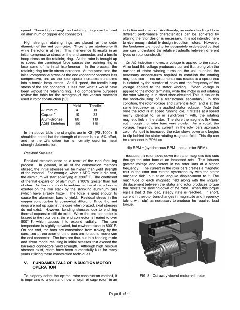
FIG. 8 - Cut away view <strong>of</strong> motor with rotor