SERVICE BULLETIN No.1191 - ABC Companies
SERVICE BULLETIN No.1191 - ABC Companies
SERVICE BULLETIN No.1191 - ABC Companies
- No tags were found...

Create successful ePaper yourself
Turn your PDF publications into a flip-book with our unique Google optimized e-Paper software.
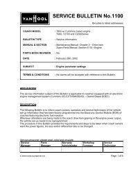
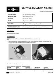
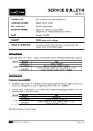
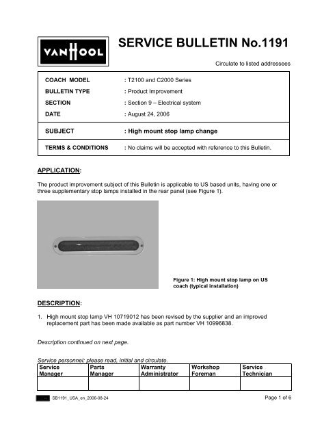
<strong>SERVICE</strong> <strong>BULLETIN</strong> <strong>No.1191</strong>Circulate to listed addresseesCOACH MODEL<strong>BULLETIN</strong> TYPESECTION: T2100 and C2000 Series: Product Improvement: Section 9 – Electrical systemDATE : August 24, 2006SUBJECTTERMS & CONDITIONS: High mount stop lamp change: No claims will be accepted with reference to this Bulletin.APPLICATION:The product improvement subject of this Bulletin is applicable to US based units, having one orthree supplementary stop lamps installed in the rear panel (see Figure 1).Figure 1: High mount stop lamp on UScoach (typical installation)DESCRIPTION:1. High mount stop lamp VH 10719012 has been revised by the supplier and an improvedreplacement part has been made available as part number VH 10996838.Description continued on next page.Service personnel: please read, initial and circulate.ServiceManagerPartsManagerWarrantyAdministratorWorkshopForemanServiceTechnicianSB1191_USA_en_2006-08-24Page 1 of 6
Continued from page 1.2. The new stop lamp has been cut into the production of T2100 units as from:Model Engine VINCummins 44328 !T2100 Detroit Diesel 44658 !Caterpillar 44832 !On commuter coaches, this type of stop lamp is no longer used since the introduction of theC2045E model.However, the new lamp will replace the old one as spare part.3. Stop lamp VH 10996838 has the following features:• It is directly interchangeable with the old one.• The recesses in the housing have been deleted (see Figures 2 and 3).This eliminates cracking of the housing/lens and ingress of moisture.This also makes for a much stiffer assembly.• The resin layer embedding the LED's and the reflector has been slightly increased for bettersealing properties.4. The terminals used to hook-up the lamp to the coach wiring have been replaced by buttconnectors, which are gel filled and gas tight.Wires are simply inserted into the housing and crimped down, which actuates an insulationdisplacement mechanism automatically connecting the two wires into an environmentally gelsealed unit.To install, a suitable crimping tool is required (see Figure 8 further in the procedure).Terminals have been replaced bywater tight connectorsVH 10996838VH 10719012VH 10719012VH 10996838Figure 2Figure 35. This Bulletin has been released to allow owners and operators to convert their units as per thenew installation should stop lamp failure occur.Page 2 of 6SB1191_USA_en_2006-08-24
PARTS AND PRODUCTS:To replace a stop lamp, following parts and products are required:VH 10698202VH 10996838Figure 4: Stop lamp VH 10996838 replacesstoplight VH 10719012Bezel VH 10698202 can be reusedFigure 5: Connector VH 10998909VH reference Description Qty.*VH 10996838 Lamp, stop 1 or 3VH 10998909 Butt connector, gel-filled 2 or 6*Depending on # installed• Old and new parts are directly interchangeable.• Parts may be obtained through regular channels.• Parts and products disposition:Failure on units covered by the Van Hool normal warranty: the regular procedures apply.Failure on units not covered by the Van Hool normal warranty: discard according to applicableenvironmental regulations.SB1191_USA_en_2006-08-24Page 3 of 6
PROCEDURE:1. General:• This job should be executed by an experienced automotive service technician.• For more information refer to:the Electrical Wiring Diagram Booklet that comes with the coach,the Maintenance Manual,the Spare Parts Manual,and the Operator's Guide Book.2. Special tools, equipment or services:• This job requires the use of pliers VH 10998914 (see Figure 6).Figure 6: Connector crimping toolVH 109989143. Preparations:• Park the coach/transit bus on a level surface service with the front wheels straight.Apply the parking brake and shut down the engine.• Switch off all systems and turn off the battery master switch.• Put a “DO NOT OPERATE” tag on the instrument panel.• Read the entire procedure before beginning to work.CAUTION: Observe safe shop practices at all times.4. To replace a high mount stop lamp:1) Undo and remove the two screws securing the stop lamp bezel to the rear panel.Carefully pry loose the bezel, taking care not to damage the paint.2) Dislodge the stop lamp from the recess in the panel.3) Take note of how the color-coded wiring of the coach matches the tracer coded lamp wiring.4) Cut the coach wiring at the terminals (see Figure 7).Page 4 of 6SB1191_USA_en_2006-08-24
5) Thoroughly clean the recess in the rear panel to accept the new lamp.Figure 7: Cut the coach/transit bus wiringat the terminals6) Referring to Figures 8 and 9 and to the notes taken in step three of this procedure, hook-upthe new lamp using butt connectors VH 10998909 and pliers VH10998914.No stripping of wire insulation is required.1 2 3Figure 8: Butt connector VH 10998909 installation procedure:1. Cut wires to length and straighten2. Separate and fully insert conductors3. Crimp with cap side down7) Install the new lamp in the recess.Figure 9: Two-wire connection completedusing butt connector VH 10998909SB1191_USA_en_2006-08-24Page 5 of 6
8) Install the bezel securing the mounting screws hand tight.9) Check brake lamp operation.Procedure complete.DISCLAIMER:The procedures contained herein are not exclusive. Van Hool cannot possibly know, evaluate, oradvise the transportation industry of all conceivable ways in which a procedure may be undertakenor of the possible consequences of each such procedure. Other procedures may be as good, orbetter, depending upon the particular circumstances involved.Each carrier who uses the procedures herein must first satisfy itself thoroughly that neither thesafety of its employees or agents, nor the safety or usefulness of any products, will be jeopardizedby any procedure selected.<strong>SERVICE</strong> INFORMATION:Service Bulletins are issued to supplement or supersede information in the Van Hool manuals. NoteService Bulletin number, date and subject on the register at the end of the relevant chapter(s). FileService Bulletin separately for future reference.Page 6 of 6SB1191_USA_en_2006-08-24