SERVICE BULLETIN No.1193 - ABC Companies
SERVICE BULLETIN No.1193 - ABC Companies
SERVICE BULLETIN No.1193 - ABC Companies

You also want an ePaper? Increase the reach of your titles
YUMPU automatically turns print PDFs into web optimized ePapers that Google loves.
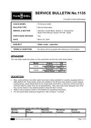
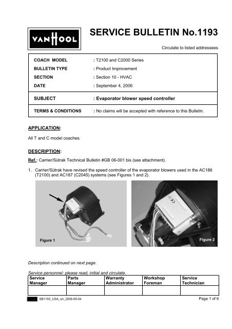
<strong>SERVICE</strong> <strong>BULLETIN</strong> <strong>No.1193</strong>Circulate to listed addresseesCOACH MODEL<strong>BULLETIN</strong> TYPESECTION: T2100 and C2000 Series: Product Improvement: Section 10 - HVACDATE : September 4, 2006SUBJECTTERMS & CONDITIONS: Evaporator blower speed controller: No claims will be accepted with reference to this Bulletin.APPLICATION:All T and C model coaches.DESCRIPTION:Ref.: Carrier/Sütrak Technical Bulletin #GB 06-001 bis (see attachment).1. Carrier/Sütrak have revised the speed controller of the evaporator blowers used in the AC186(T2100) and AC187 (C2045) systems (see Figures 1 and 2).Figure 1 Figure 2Description continued on next page.Service personnel: please read, initial and circulate.ServiceManagerPartsManagerWarrantyAdministratorWorkshopForemanServiceTechnicianSB1193_USA_en_2006-09-04Page 1 of 6
Continued from page 1.2. The connector attaching the speed controller wiring to the printed circuit board has beendeleted. The wires are now soldered directly onto the printed circuit board, protected by shrinktubing, resin-cast and secured by a cable tie.3. New speed controllers have been cut into production as from following units:Model Engine VINT2140Cummins 40160 !Detroit Diesel 40622 !Cummins 44331 !T2145 Detroit Diesel 44662 !Caterpillar 44833 !Cummins 46078 !C2045 Detroit Diesel 46723 !Caterpillar 47294 !4. The procedure in this Bulletin describes the steps required to replace the old speed controller bythe new one in case of failure.PARTS AND PRODUCTS:Old partsVH reference Description Qty.*VH 632803235 Speed controller #26.09.10.001, evaporator blower 1*Quantities per blowerNew partsVH reference Description Qty.*VH 10996158 Speed controller, #26.09.10.006-00, evaporator blower 1*Quantities per blower• Old and new parts are interchangeable, but only the new will be offered for service replacement.• Parts may be purchased from your nearest <strong>ABC</strong> Customer Care & Parts Source service center.• Parts and products disposition: discard according to applicable environmental regulations.PROCEDURE:If you do not have the expertise to perform present procedure, do not hesitate to go to your nearest<strong>ABC</strong> Customer Care & Parts Source dealership.1. General:• This job should be executed by an experienced automotive electrician• For more information refer tothe Electrical Wiring Diagram Booklet that comes with the coachthe Maintenance Manualthe Operator's Guide BookPage 2 of 6SB1193_USA_en_2006-09-04
2. Special tools, equipment or services:• No special tools, equipment or services are required.3. Preparations:• Park the coach on a level surface with the front wheels straight.Apply the parking brake and shut down the engine.• Switch off all systems and turn off the battery master switch.• Put a “DO NOT OPERATE” tag on the instrument panel.• Read the entire procedure before beginning to work.CAUTION: Observe safe shop practices at all times.4. To replace the evaporator blower speed controller (T2100):The blowers are located on both sides of the heater/evaporator assembly in the parcel racks.Each blower has its own speed controller bolted to it (see Figure 2).1) To open the panel giving access to the affected blower(s), undo and remove the panelmounting screws (see Figure 3). Slide the panel aside to release it from its retaining bracket.The blowers are now visible (see Figure 4).Figure 3: T2100 evaporator blower accessdoor (left-hand)NOTE: Most of the blowers are readily accessible to replace the speed controller.If the controller is inaccessible, first remove the blower from the air duct by undoing themounting bolts.SB1193_USA_en_2006-09-04Figure 4: T2100 evaporator blower bank(left-hand)Page 3 of 6
NOTE: Blowers are directional (left-hand and right-hand). Improper installation will impairefficiency.2) Take note of the blower and speed controller wiring hook-up.Undo the speed controller connectors.3) Take note of the speed controller installation.Undo and remove the fastener(s) securing the speed controller to the blower housing.Recover the hardware.NOTE: Parts may be obtained free of charge. In order to be eligible for a free assembly, theold part must be returned. Applicable to coaches under warranty only.4) Install the new controller on the blower housing.Tightening torque for the controller mounting hardware is 22 in.lbf (24 Nm).5) Hook-up the controller and blower wiring to the coach wiring.6) If applicable, reinstall the blower in its former location.Tightening torque for the blower mounting hardware is 22 in.lbf (24 Nm).7) Continue speed controller replacement on other blowers as required.8) Close and secure the blower access panel(s).5. To replace the evaporator blower speed controller (C2045):The blowers are located behind the heater/evaporator assembly in the parcel racks. Eachblower has its own speed controller bolted to it (see Figure 2).1) Using a flat blade screwdriver, unlatch the door giving access to the affected blower(s)(see Figure 5). This may take a few counter-clockwise turns of the screwdriver.Lower the door. The blowers are now visible (see Figure 6).F04879F04906Figure 5: C2045 evaporator blower accessdoor (left-hand parcel rack)Figure 6: C2045 evaporator blower bank(left-hand parcel rack)Page 4 of 6NOTE: On commuter coaches the controller is inaccessible without first removing the blowerand shroud assembly from the blower bank in the air duct. Remove the affected blower andshroud assembly by undoing and removing the six M6 mounting bolts.SB1193_USA_en_2006-09-04
2) Take note of the blower and speed controller wiring hook-up.Undo the speed controller connectors.3) Take note of the speed controller installation.Undo and remove the fastener(s) securing the speed controller to the blower housing.Recover the hardware.NOTE: Parts may be obtained free of charge. In order to be eligible for a free assembly, theold part must be returned. Applicable to coaches under warranty only.4) Install the new controller on the blower housing.Tightening torque for the controller mounting hardware is 22 in.lbf (24 Nm).5) Hook-up the controller and blower wiring to the coach wiring.6) Reinstall the blower and shroud assembly in its former location.Tightening torque for the M6 mounting bolts is 80 in.lbf (9 Nm).7) Continue speed controller replacement as required.8) Close and secure the blower access door.Procedure complete.DISCLAIMER:The procedures contained herein are not exclusive. Van Hool cannot possibly know, evaluate, oradvise the transportation industry of all conceivable ways in which a procedure may be undertakenor of the possible consequences of each such procedure. Other procedures may be as good, orbetter, depending upon the particular circumstances involved.Each carrier who uses the procedures herein must first satisfy itself thoroughly that neither thesafety of its employees or agents, nor the safety or usefulness of any products, will be jeopardizedby any procedure selected.<strong>SERVICE</strong> INFORMATION:Service Bulletins are issued to supplement or supersede information in the Van Hool manuals. NoteService Bulletin number, date and subject on the register at the end of the relevant chapter(s). FileService Bulletin separately for future reference.ATTACHMENTS:Carrier/Sütrak Technical Bulletin #GB 06-001 bis "Speed controller".SB1193_USA_en_2006-09-04Page 5 of 6
THIS PAGE HAS BEEN LEFT BLANK INTENTIONALLYPage 6 of 6SB1193_USA_en_2006-09-04
Date: 1 st March 2006 No.: GB 06-001 bisDistribution:Category: Product InformationSubject : SPEED CONTROLLER Department: Customer QualityPart number26,09,10,001 speed controllerPicture 1 – On the right the old speed controller - part # 26,09,10,001On the left the new one - part # 26,09,10,006-00Description of product improvementIn isolated cases, due to an intermittent contact between the wiring connector pin and the speedcontroller socket, the speed controller wire terminal has shown signs of malfunctioning.This condition can produce improper speed controller operation.In order to address the issue, the speed controller design has been improved.The connector of the harness cables on the PCB (printed circuit board) has been deleted.The wires are now soldered directly to the PCB; additionally they will be glued and fixed with a hoseand a cable tie (see pictures).New part numberThe new part number is 26,09,10,006-00. The new part number is replacing the old one effectiveimmediately for both production and spare parts.The old cable set available as a spare part (part number 63,52,02,002) will not be usable any moreafter the modification.
New parts availability and installationDuring the warranty period of the vehicle, replacement parts for old speed controllers showing the abovementioned failure may be obtained Free of Charge on a one for one exchange basis.Old and new parts are directly interchangeable, but only the new will be offered as servicereplacements.Picture 2&3 – detail of the new speed controller - part # 26,09,10,006-00Picture 4 – new speed controller - part # 26,09,10,006-00