SLP Twin Pipes for 2005-06 Arctic Cat - Starting Line Products, Inc.
SLP Twin Pipes for 2005-06 Arctic Cat - Starting Line Products, Inc.
SLP Twin Pipes for 2005-06 Arctic Cat - Starting Line Products, Inc.

You also want an ePaper? Increase the reach of your titles
YUMPU automatically turns print PDFs into web optimized ePapers that Google loves.
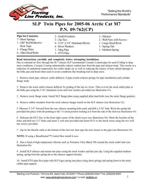
Pipe Set Contents:<br />
7 - Short Springs<br />
1 - 240” Roll Reflective<br />
Heat Tape<br />
1 - Flange Plate<br />
6 - Allen Head Bolts<br />
<strong>SLP</strong> <strong>Twin</strong> <strong>Pipes</strong> <strong>for</strong> <strong>2005</strong>-<strong>06</strong> <strong>Arctic</strong> <strong>Cat</strong> M7<br />
P.N. 09-762(CP)<br />
2 - Grafoil Gaskets<br />
3 - Zip Ties<br />
6 - 3/16” x 3/4” Aluminum Rivets<br />
6 - Rivet Washers<br />
1 - Mag Pipe<br />
1 - PTO Pipe<br />
Read instructions carefully and completely be<strong>for</strong>e attempting installation.<br />
Due to minimal air flow through the M-7 chassis <strong>SLP</strong> recommends Ceramic Coated pipes be used if riding in deep<br />
snow conditions. Ceramic Coating substantially reduces radiant heat from the pipe and silencer body. This results in a<br />
reduction of underhood temperature <strong>for</strong> cooler intake air as well as reducing the chance of heat related damage to<br />
the belly pan and hood when used in severe conditions like breaking trail in deep snow.<br />
1. Remove stock pipe, silencer, outlet deflector, Y-pipe (retain exhaust springs <strong>for</strong> pipe installation) and cylinder<br />
flange studs.<br />
2. Remove the stock outlet exhaust deflector by griding of the top six rivtes. Then re-rivet the stock outlet plate to<br />
the belly pan using the 3/16” aluminum rivets and rivet washers provided (see illustration #1).<br />
3. Remove stock flange studs. Install <strong>SLP</strong> flange plate using supplied allen head bolts (use the stock flange gaskets).<br />
4. Remove rubber insulator from the stock silencer hanger install on the <strong>SLP</strong> silencer (see illustraiton #2).<br />
5. Measure 2 1/4” <strong>for</strong>ward from the rear silencer mounting hole mark and drill a 3/16” hole. Rivet the spring tab<br />
provided into place with tab pointing to the 7 o’clock position looking at it from the side of the sled (see illustration #3)<br />
6. Relocate the ECU box to the front right corner of the shock tower (see illustration #4). Mark the location of the<br />
holes and drill two 1/2” holes and insert 2 well nuts provided and fasten ECU to the shock tower using the two well<br />
nut screws provided.<br />
7. Zip tie the throttle cable to the bottom of the fuel rail, heat tape the area closest to the pipe (see illustration #5).<br />
NOTE: If using a BoonDocker Control Box install it now.<br />
“Setting the World’s<br />
Per<strong>for</strong>mance Standards”<br />
1 - Silencer<br />
2 - Well Nuts with Screws<br />
1 - Large Head Rivet<br />
1 - Spring Tab<br />
1 - Medium Spring<br />
8. Run a bead of high temperature silicone such as Permatex Ultra Black 598 around the stock outlet hole (see<br />
illustration #6).<br />
9. Install <strong>SLP</strong> silencer and mount into place using the stock washer and hair pin clip. Using the supplied medium<br />
spring, spring from the spring tab to the silencer support bracket.<br />
10. Install PTO pipe first (pipe with <strong>SLP</strong> logo) spring into place using short springs and spring down to the stock<br />
rubber pipe support.<br />
<strong>Starting</strong> <strong>Line</strong> <strong>Products</strong> • 743 Iona Rd. Idaho Falls, ID 83401 • Phone (208)529-0244 • Fax (208)529-9000<br />
web: www.startinglineproducts.com • e-mail: slp@slp.cc<br />
1
09-762 6-6-05<br />
NOTES:<br />
- Injectors may need to be rotated <strong>for</strong> pipe clearance and zip tied to the fuel rail.<br />
- If clearance is needed on the fuel rail the stock rubber pipe support can be trimmed down.<br />
- <strong>2005</strong> models need to remove under hood foam mat and then heat tape the hood in the areas closes to the<br />
pipe.<br />
11. Install Mag pipe and spring into place using short springs. Spring Mag pipe to he PTO pipe using one of<br />
the short springs provided.<br />
NOTE: Silicone pipe to silencer joint with a high temp. silicone such as Permatex Ultra Black 598.<br />
12. Install heat tape to the areas closest to the pipe and silencer including exhaust valve servo motor cover,<br />
coolant bottle, oil bottle and cap and the side of the belly pan closest to the silencer.<br />
<strong>SLP</strong> recommends the use of the air intake kit P.N.14-291.<br />
Spring Tension Adjustment:<br />
Spring loop adjustment is suggested <strong>for</strong> proper spring tension to prevent leakage and wear (low tension), allow<br />
adequate flex (proper tension) and prevent spring breakage (excessive tension).<br />
When system is installed the spring can be judged <strong>for</strong> proper tension. The winding spacing at the center of the<br />
spring will indicate tension. When proper the two center windings will have .040" to .050" clearance between<br />
them. This is easily tested with a feeler gage.<br />
If tension is incorrect, the loop on the pipe or silencer can be bent in the direction needed to increase or<br />
decrease tension. Attach a vise grip firmly to the loop and bend.<br />
ILLUSTRATION #1<br />
<strong>Starting</strong> <strong>Line</strong> <strong>Products</strong> • 743 Iona Rd. Idaho Falls, ID 83401 • Phone (208)529-0244 • Fax (208)529-9000<br />
web: www.startinglineproducts.com • e-mail: slp@slp.cc<br />
2
09-762 6-6-05<br />
ILLUSTRATION #2<br />
ILLUSTRATION #3<br />
<strong>Starting</strong> <strong>Line</strong> <strong>Products</strong> • 743 Iona Rd. Idaho Falls, ID 83401 • Phone (208)529-0244 • Fax (208)529-9000<br />
web: www.startinglineproducts.com • e-mail: slp@slp.cc<br />
3
ILLUSTRATION #4<br />
Run a bead of<br />
silicone around outlet<br />
ILLUSTRATION #5
ILLUSTRATION #6<br />
Run a bead of silicone<br />
around the outlet<br />
Caring <strong>for</strong> your ceramic coated pipes and/or silencer:<br />
Ceramic Coating is an aluminum matrix applied to your exhaust system to provide a thermal barrier<br />
<strong>for</strong> more consistent per<strong>for</strong>mance. It is a coating which requires little maintenance to keep your pipes<br />
and/or silencer looking like new.<br />
Upon completion of new installation, wipe the ceramic coated parts of the exhaust system down with<br />
brake cleaner. This will prevent oils and grease (usually in the <strong>for</strong>m of fingerprints) from burning on and<br />
staining the exhaust during first initial startup.<br />
To maintain your ceramic coated system, wash it with soap and water periodically (especially<br />
necessary after trailering it to and from your riding area on roads that have been treated with salt and<br />
other ice removing chemicals). Salt and other ice removing chemicals will attack and eat away at the<br />
ceramic coating. This will result in rust coming through the coating. Typically you will notice this rusting<br />
after your snowmobile has set <strong>for</strong> a period of time without the exhaust system being brought up to<br />
running temperature.<br />
Periodically polish your ceramic coated pipes and/or silencer after each washing with an aluminum<br />
polish such as Mothers, Maas or Blue Magic aluminum polish that can be found at any automotive parts<br />
store. Do not use any acidic cleaners! For stubborn stains use fine 000 steel wool, then use a soft<br />
cloth with polish. Failure to maintain your ceramic coated pipes or silencer can result in damage to the<br />
ceramic coating <strong>for</strong> which there is no warranty coverage. A little care will insure that your pipes and/or<br />
silencer will continue looking like new <strong>for</strong> many years.<br />
Note: In areas of the ceramic coated system where skin temperatures exceed 1300 degrees F, it is<br />
normal <strong>for</strong> the coating to turn dull gray. These areas should also be washed and polished periodically.<br />
<strong>Starting</strong> <strong>Line</strong> <strong>Products</strong> • 743 Iona Rd. Idaho Falls, ID 83401 • Phone (208)529-0244 • Fax (208)529-9000<br />
web: www.startinglineproducts.com • e-mail: slp@slp.cc<br />
4
09-762 12-29-<strong>06</strong><br />
Fuel Map Guideline<br />
<strong>Arctic</strong> <strong>Cat</strong> M-7 EFI with <strong>SLP</strong> <strong>Twin</strong> <strong>Pipes</strong> and <strong>SLP</strong> Air Horn Kit<br />
using BoonDocker Per<strong>for</strong>mance Control Box<br />
Important Note: The following in<strong>for</strong>mation is given as a guideline only. The fuel<br />
map listed was attained using a <strong>2005</strong> M-7 stock engine, stock airbox, with <strong>SLP</strong><br />
twin pipes. Fuel used was premium 91 octane non oxygenated.<br />
<strong>SLP</strong> recommends that you start at a richer setting than what is listed below and<br />
lean down as needed <strong>for</strong> best per<strong>for</strong>mance using plug color as a guideline. Exhaust<br />
temperature gauges can also be used as a tuning aid, but due to differences<br />
in gauges, probes, probe position as well as many other engine variables you must<br />
first establish a relationship between plug color and exhaust gas temperature.<br />
Fuel: Minimum 91 octane pump fuel. Fuels containing ethanol or oxygen carrying<br />
additives will require more fuel than non oxygen carrying fuels.<br />
Fuel Map <strong>for</strong> <strong>Arctic</strong> <strong>Cat</strong> M-7<br />
RPM Low Mid High Trim<br />
3000 -03 00 00 00<br />
5000 00 03 00 00<br />
6700 00 00 -13 00<br />
7800 00 00 07 00<br />
8100 00 00 <strong>06</strong> 00<br />
<strong>Starting</strong> <strong>Line</strong> <strong>Products</strong> • 743 Iona Rd. Idaho Falls, ID 83401 • Phone (208)529-0244 • Fax (208)529-9000<br />
web: www.startinglineproducts.com • e-mail: slp@slp.cc<br />
5
09-762 11-25-05<br />
Jetting <strong>for</strong> Carbureted <strong>Arctic</strong> <strong>Cat</strong> M-7<br />
with <strong>SLP</strong> <strong>Twin</strong> <strong>Pipes</strong> and <strong>SLP</strong> High Flow Intake P.N. 14-291<br />
Altitude<br />
6-8000'<br />
(1800-2400m)<br />
8-10,000'<br />
(2400-3000m)<br />
0' (0m)<br />
Altitude<br />
2000' (610m)<br />
4000' (1219m)<br />
6000' (1829m)<br />
8000' (2438m)<br />
10,000' (3048m)<br />
+12,000' (+3658m)<br />
Clutching <strong>for</strong> <strong>Arctic</strong> <strong>Cat</strong> M-7 w/<strong>SLP</strong> <strong>Twin</strong> <strong>Pipes</strong> and<br />
High Flow Intake Kit<br />
<strong>SLP</strong><br />
MTX Weights<br />
68 g<br />
1 g rivet<br />
outer hole<br />
P.N. 40-95<br />
68 g<br />
no rivets<br />
P.N. 40-95<br />
-40 to -20°F<br />
(-40 to -29°C)<br />
Drive Clutch Driven Clutch<br />
Spring Torque Bracket Spring<br />
<strong>SLP</strong><br />
Green / Pink<br />
P.N. 40-77<br />
<strong>SLP</strong><br />
Green / Pink<br />
P.N. 40-77<br />
-20 to 0°F<br />
(-29 to -18°C)<br />
Temperature<br />
36º<br />
(stock)<br />
36º<br />
(stock)<br />
0 to 20°F<br />
(-18 to -7°C)<br />
White<br />
(Stock)<br />
White<br />
(Stock)<br />
20 to 40°F<br />
(-7 to 4°C)<br />
PTO/MAG PTO/MAG PTO/MAG PTO/MAG<br />
600<br />
#5<br />
500<br />
#4<br />
460<br />
#3<br />
410<br />
#2<br />
400<br />
#1<br />
390<br />
#1<br />
380<br />
#1<br />
Recommended Jet Needle: 9EJ1 stock (# below main jet indicates e-clip position)<br />
Spark Plug Recommendation: BR9EYA<br />
Important Note: Fuels containing ethanol, alcohol based fuel compounds, or oxygen carrying<br />
additives will require larger main jets, usually 2 sizes more than the <strong>SLP</strong> jetting chart. Jet Needle<br />
may need to be raised one “E” clip position.<br />
Carburetor Tuning Note: Carb tuning specifications included in this section are a base line<br />
and should be adjusted as needed <strong>for</strong> your atmosphere. <strong>SLP</strong> recommends that you monitor your<br />
plug color and piston wash to verify jetting. Exhaust gas temperature guages can also be used<br />
as a tuning aid, but due to differences in guages, probes, probe position as well as many other<br />
engine variables you must first establish a relationship between piston wash and exhaust gas<br />
temperature.<br />
580<br />
#5<br />
490<br />
#4<br />
450<br />
#3<br />
400<br />
#2<br />
390<br />
#1<br />
380<br />
#1<br />
370<br />
#1<br />
560<br />
#4<br />
480<br />
#4<br />
440<br />
#3<br />
390<br />
#2<br />
380<br />
#1<br />
370<br />
#1<br />
360<br />
#1<br />
540<br />
#4<br />
460<br />
#3<br />
430<br />
#3<br />
380<br />
#2<br />
370<br />
#1<br />
360<br />
#1<br />
350<br />
#1<br />
Running RPM<br />
8000-8200<br />
Important Notes:<br />
- Using a new belt, check belt to sheave clearance to insure it is withing tolerance<br />
(0.010 - 0.020”).<br />
- Using a new belt, check belt delfection, it should measure 1 1/4”.<br />
<strong>Starting</strong> <strong>Line</strong> <strong>Products</strong> • 743 Iona Rd. Idaho Falls, ID 83401 • Phone (208)529-0244 • Fax (208)529-9000<br />
web: www.startinglineproducts.com • e-mail: slp@slp.cc<br />
6