EVC Laser Marking System - Telesis Technologies, Inc.
EVC Laser Marking System - Telesis Technologies, Inc.
EVC Laser Marking System - Telesis Technologies, Inc.

Create successful ePaper yourself
Turn your PDF publications into a flip-book with our unique Google optimized e-Paper software.
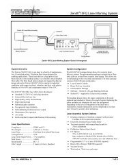
<strong>EVC</strong> <strong>Laser</strong> <strong>Marking</strong> <strong>System</strong><br />
SYSTEM SPECIFICATIONS<br />
Compliance ............................... CDRH<br />
<strong>Laser</strong> Type ................................ fiber-coupled, diode-pumped,<br />
Q-switched, Nd:YVO4<br />
Wavelength ............................... 1064 nanometers (nm)<br />
Mode ......................................... TEM00<br />
<strong>System</strong> Power (total)................. < 400 watts<br />
Average Power ........................ 8 watts<br />
Long Term Output Power Drift .. < ± 2%<br />
Expected Diode Lifetime ........... > 25,000 hours<br />
Power Requirements ................ 95 to 250 VAC, single-phase,<br />
6A, 50/60 Hz<br />
Supply Voltage Fluctuation ....... < ±10% with clean ground line<br />
Operational Temperature.......... 18° to 35°C (65° to 95°F)<br />
Recommended Temperature .... 20° to 25°C (68° to 77°F)<br />
Ambient Relative Humidity........ 10% to 85% non-condensing<br />
SYSTEM OPTIONS<br />
• Desktop computer or notebook computer with powered<br />
cardbus-to-PCI expansion enclosure<br />
• Remote pushbutton station (start/abort)<br />
• Externally-mounted focus-finder diode<br />
• I/O options (see Remote Communications for details):<br />
TTL via PCI-DIO24 Board<br />
Opto-isolated via Merlin DCIO Module<br />
Two-axis Controller<br />
• Manually operated tool post for vertical (z-axis)<br />
adjustment<br />
• Programmable tool post for vertical (z-axis) adjustment<br />
(requires two-axis controller)<br />
• Rotary drive fixture for rotational (theta-axis) adjustment<br />
(requires two-axis controller)<br />
• Workstation / work area enclosure<br />
• Fume extraction systems<br />
2 of 10 72353-<br />
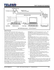
SYSTEM SETUP<br />
The following procedures are listed for reference only to<br />
provide a general overview of the installation process. Refer to<br />
the <strong>EVC</strong> Installation & Maintenance Manual for complete<br />
installation details.<br />
Do not connect any power cable to power source<br />
until all system connections are made.<br />
1. All equipment must remain powered down and in OFF<br />
position until mounting is complete.<br />
2. Place the laser controller, system computer, monitor,<br />
keyboard, and mouse in the desired locations. Locate the<br />
laser controller as close as practical to the laser marking<br />
head.<br />
3. Ensure sufficient clearance exists on all sides of the laser<br />
controller to allow for proper air circulation and to<br />
permit proper installation of applicable cables. Refer to<br />
the XP1C <strong>Laser</strong> Controller Dimensions drawing for<br />
details.<br />
4. Place the laser marking head on a suitable mounting<br />
surface.<br />
5. Ensure sufficient clearance exists on all sides of the laser<br />
marking head to allow for proper air circulation and to<br />
permit proper installation of applicable cables. Refer to<br />
the <strong>EVC</strong> <strong>Laser</strong> <strong>Marking</strong> Head Dimensions drawing for<br />
details.<br />
6. Mount the laser marking head with three M5-0.80 bolts<br />
and lock washers using the factory-tapped mounting<br />
holes provided. Refer to the <strong>EVC</strong> <strong>Laser</strong> <strong>Marking</strong> Head<br />
Dimensions drawing for details.<br />
Note: Optionally, three M6 locating pins may be used<br />
at the 0.2362 P6 hole locations for more precise<br />
marking head alignment.<br />
7. Select proper fuse arrangement for the laser controller.<br />
Refer to the <strong>EVC</strong> Installation & Maintenance Manual.<br />
8. Connect all cables as applicable (fiber optic cable, laser<br />
marking head cable, RF cable, galvo control cable,<br />
computer monitor, keyboard, mouse, and power cables).<br />
9. Connect any optional or customer-supplied devices or<br />
interface circuits as applicable.<br />
10. Refer to the <strong>EVC</strong> Operation Supplement for proper<br />
startup procedure. Refer to the Merlin II LS Operating<br />
Instructions for complete information on using the<br />
system software.