CO30 Laser Marking System - Telesis Technologies, Inc.
CO30 Laser Marking System - Telesis Technologies, Inc.
CO30 Laser Marking System - Telesis Technologies, Inc.

You also want an ePaper? Increase the reach of your titles
YUMPU automatically turns print PDFs into web optimized ePapers that Google loves.
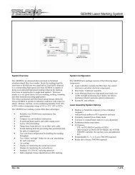
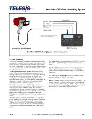
<strong>System</strong> Overview<br />
The <strong>Telesis</strong> ® <strong>CO30</strong> is a 30W, RF-excited, sealed-tube, CO2 laser<br />
marking system that provides a galvo-steered beam designed for<br />
marking. The <strong>CO30</strong> laser marking system is excellent for marking<br />
substrates like wood, glass, Plexiglas ® , quartz, ceramics, fabrics,<br />
and other organic materials.<br />
The <strong>CO30</strong> laser offers these advantages:<br />
• Air-cooling – no external water or refrigerant needed<br />
• Compact laser marking head and simple mounting system<br />
• Detachable 6 ft. (1.8m) umbilical cable for easy integration<br />
• Key switch, <strong>Laser</strong> Off palm button, interlocked safety<br />
shutter, and emission indicators<br />
• DoD-compliant Unique Identification (UID) marking<br />
<strong>System</strong> Configuration<br />
The <strong>CO30</strong> is available in two configurations. One is capable of<br />
marking only stationary objects. The other is capable of marking<br />
objects while they are moving (i.e., mark-on-the-fly operation).<br />
The basic laser system consists of the following components.<br />
<strong>Laser</strong> Controller – contains circuit boards, electrical<br />
components, and the operator console<br />
Umbilical Cable Assembly – includes power and data cables<br />
<strong>Laser</strong> <strong>Marking</strong> Head –includes the laser cavity, optics, shutter<br />
assembly, galvanometer assembly, and flat-field lens. A red<br />
aiming diode is included with markers configured for<br />
stationary marking (optional for mark-on-the-fly markers).<br />
Software – Merlin ® II LS <strong>Laser</strong> <strong>Marking</strong> Software<br />
<strong>System</strong> Computer – supplied by <strong>Telesis</strong> or by customer<br />
The modular design allows for major components to be easily<br />
replaced and returned to <strong>Telesis</strong> if required.<br />
<strong>CO30</strong> <strong>Laser</strong> <strong>Marking</strong> <strong>System</strong> – General Arrangement<br />
<strong>CO30</strong> <strong>Laser</strong> <strong>Marking</strong> <strong>System</strong><br />
<strong>Laser</strong> <strong>System</strong> Options<br />
• Hand-held pendant for convenient remote operation (shutter<br />
open/close; emission indicator)<br />
• Co-axial red aiming diode for pin point marking alignment<br />
with markers configured for mark-on-the-fly (standard with<br />
markers configured for stationary marking).<br />
• Pushbutton station (start/abort)<br />
• Externally-mounted focus-finder diode<br />
• Mark-on-the-fly kit to interface with customer-supplied<br />
encoder for marking objects in linear or circular motion<br />
• Desktop computer or Notebook computer with powered<br />
cardbus-to-PCI expansion enclosure<br />
• Programmable X-, Y, or Z-axis (requires two-axis controller)<br />
• Tool post w/ manual hand crank for z-axis adjustment<br />
• Rotary drive fixture<br />
(requires two-axis controller)<br />
• I/O Options:<br />
TTL via PCI-DIO24 Card (Kit #53920)<br />
Opto-isolated via Merlin DCIO Module (Kit #53928)<br />
Two-axis Controller (for auxiliary axes; additional I/O)<br />
• Workstation / Work Area Enclosures<br />
• Fume Extraction Vacuum <strong>System</strong>s<br />
Doc No. 47713 Rev. E © 2006 – 2009 <strong>Telesis</strong> <strong>Technologies</strong>, <strong>Inc</strong>. – All Rights Reserved 1 of 7
<strong>System</strong> Setup<br />
Complete installation procedures are provided in the <strong>CO30</strong><br />
Installation/Maintenance Manual. The following procedures are<br />
listed for reference only to provide a general overview of the<br />
installation process.<br />
1. Equipment should remain powered down and in the OFF<br />
position until the mounting is complete.<br />
2. Place the computer, monitor keyboard and laser controller in<br />
the desired location. Locate the controller as close as<br />
practical to the laser marking head. The standard umbilical<br />
length is 1.8 meters (6 feet).<br />
3. Place the laser marking head onto the mounting position<br />
taking care not to bend or kink the umbilical cable. The<br />
umbilical cable will take an approximately 200 mm (8 in.)<br />
diameter bend without damage.<br />
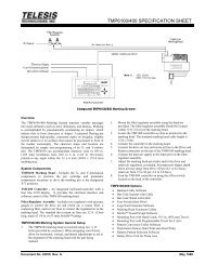
4. Mount the laser marking head per the following guidelines:<br />
• A minimum distance of 200 mm (8 in.) should be allowed<br />
at the rear of the laser marking head to allow for proper<br />
installation of the umbilical.<br />
• Mount the laser marking head using three M8-1.25 bolts<br />
and lock washers. Torque to 191 in-lbs (21.59 N-m).<br />
• Mounting bolts must not extend into the laser<br />
marking head as to interfere with the internal<br />
components or the optical beam path.<br />
• Refer to the Dimensions and Mounting Details drawing<br />
for mounting bolt locations and note the following:<br />
– Pay particular attention to the location of the<br />
center of the marking window as dimensioned on<br />
the appropriate mounting drawing (see next page).<br />
– The leading edge of the mounting plate should be no<br />
greater than 31.7mm (1.25 in.) from the first set of<br />
holes to allow clearance for the beam output lens.<br />
5. Ensure laser controller power switch (on front panel) is OFF.<br />
6. Connect the remaining cables.<br />
7. Refer to the <strong>CO30</strong> Operation Supplement for proper startup<br />
procedure of the complete system.<br />
8. Refer to the laser marking system Operation Manual for<br />
complete information on using the system software.<br />
<strong>CO30</strong> <strong>Laser</strong> <strong>Marking</strong> <strong>System</strong><br />
<strong>System</strong> Specifications<br />
Compliance .................................CDRH<br />
<strong>Laser</strong> Type...................................RF-excited, continuous wave,<br />
sealed-tube, carbon dioxide laser<br />
Wavelength .................................10.6 micrometers (µm)<br />
CW Average Power ....................30 watts<br />
Long Term Output Power Drift ...< ±5%<br />
Total Power Consumption...........approx. 6.0 amps at 115 VAC<br />
Input Power .................................115 VAC, single-phase,<br />
15A, 50/60Hz<br />
230 VAC, single-phase,<br />
7.5A, 50/60Hz<br />
Supply Voltage Fluctuation.........< ±10% with clean ground line<br />
Operational Temperature.............15° to 30°C (59° to 86°F)<br />
Recommended Temperature........16° to 24°C (61° to 75°F)<br />
Ambient Relative Humidity ........10% to 90% non-condensing<br />
<strong>Laser</strong> <strong>Marking</strong> Head<br />
The laser marking head incorporates the latest technology in<br />
sealed-tube, RF-excited, carbon dioxide lasers, providing excellent<br />
output power, stability, and reliability in a rugged compact<br />
modular package.<br />
<strong>Laser</strong> <strong>Marking</strong> Head Specifications<br />
Dimensions (L x W x H) .............973.5 x 146.88 x 204.5 mm<br />
(38.33 x 5.78 x 8.05 in.)<br />
Surrounding Envelope.................1181 x 355 x 405 mm<br />
(46.5 x 14.0 x 16.0 in.)<br />
Mounting Weight .......................approx. 21.82 Kg (48 lbs.)<br />
Mounting Holes...........................three factory-tapped M8-1.25<br />
Positioning...................................visible red aiming diode (optional<br />
for mark-on-the-fly systems)<br />
Field Resolution ..........................16 bit (65535 data points)<br />
Galvanometer Repeatability ........< 22 micro radian<br />
<strong>Marking</strong> Field Size .....................lens-dependent, see chart<br />
<strong>Laser</strong> Umbilical Cable Length.....1.8 m (6 ft.), detachable<br />
Cooling........................................air cooled, fan/filter<br />
Doc No. 47713 Rev. E 2 of 7
<strong>CO30</strong> <strong>Laser</strong> <strong>Marking</strong> Head with 7mm Galvo – Dimensions and Mounting Details<br />
<strong>CO30</strong> <strong>Laser</strong> <strong>Marking</strong> Head with 10mm Galvo – Dimensions and Mounting Details<br />
<strong>CO30</strong> <strong>Laser</strong> <strong>Marking</strong> <strong>System</strong><br />
Doc No. 47713 Rev. E 3 of 7
Visible Red Aiming Diode<br />
<strong>Laser</strong> marking heads configured to mark stationary objects include<br />
a visible red diode that can be viewed on the work surface without<br />
the need for protective safety goggles. (The aiming diode is<br />
optional for systems with mark-on-the-fly capability).<br />
The aiming diode provides a safe and convenient aid for laser<br />
setup and part programming. Since the red beam is located after<br />
the shutter, the aiming beam may be used with the shutter opened<br />
or closed. Additionally, the visible red beam may be used with the<br />
lasing beam during the marking cycle. Note that protective<br />
eyewear must always be worn when the laser is in operation.<br />
<strong>Marking</strong> Field Size<br />
The size of the marking field is dependent on lens type.<br />
See Flat-Field Lens.<br />
<strong>Marking</strong> Depth. Simple laser parameters can be operator<br />
programmed to create depths ranging from simple surface<br />
discoloration, shallow laser etching or deep laser engraving.<br />
<strong>Marking</strong> depth is dependent on several factors including; material,<br />
lens type selected and other laser parameters. Please contact<br />
<strong>Telesis</strong> for the proper setting for your specific application.<br />
Flat-Field Lens<br />
The flat-field lens is key to the marking performance of the<br />
system. This is the final coated optical lens that the beam will pass<br />
through before it strikes the marking target. This lens is called a<br />
flat field lens because when the beam is focused, the focus lies in a<br />
plane perpendicular to the optical axis of the lens.<br />
The following chart outlines the available lenses, the resulting<br />
image field provided by the lens, and the working clearance (in<br />
millimeters and inches).<br />
Lens<br />
Image Field<br />
(mm) (in.)<br />
Working<br />
Clearance<br />
(mm) (in.)<br />
75 mm 50 x 50 1.97 x 1.97 54 2.13<br />
100 mm 70 x 70 2.76 x 2.76 81 3.19<br />
150 mm 100 x 100 3.94 x 3.94 131 5.16<br />
200 mm 140 x 140 5.51 x 5.51 183 7.20<br />
250 mm 170 x 170 6.69 x 6.69 233 9.17<br />
300 mm 205 x 205 8.07 x 8.07 282 11.10<br />
360 mm 250 x 250 9.84 x 9.84 351 13.82<br />
<strong>CO30</strong> <strong>Laser</strong> <strong>Marking</strong> <strong>System</strong><br />
<strong>Laser</strong> Controller<br />
Design to meet CDRH standards, the laser controller is remotely<br />
connected to the laser marking head by a 1.8-meter (6-foot)<br />
umbilical. The umbilical is a combined multi-cable assembly that<br />
carries power and control signals to the laser marking head.<br />
The laser controller provides the electrical control of the laser<br />
marking system. The controller connects to the 115/230 VAC<br />
facility electrical supply to provide power to the laser marking<br />
system. The laser controller is also the electrical interface between<br />
the laser marking software (installed on the system computer) and<br />
the laser marking head. It provides buttons and indicators to<br />
control and monitor the laser marking process.<br />
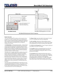
Operator Control Panel<br />
The laser control panel includes the system enable key switch, a<br />
start pushbutton, laser off palm button, safety shutter open and<br />
shutter close controls, and a laser on (emission) indicator.<br />
CO2 <strong>Laser</strong> Controller – Front Panel<br />
<strong>Laser</strong> Controller Specifications<br />
Dimensions (W x H x D).......492.0 x 201.7 x 481.7 mm<br />
(19.37 x 7.94 x 18.96 in.)<br />
Surrounding Envelope...........685 x 406 x 685 mm<br />
(27.0 x 16.0 x 27.0 in.)<br />
Weight...................................approx. 14.3 Kg (31.5 lbs.)<br />
Cooling..................................air cooled, fan/filter<br />
Doc No. 47713 Rev. E 4 of 7
<strong>System</strong> PC<br />
The laser system requires an IBM-compatible computer for<br />
running the Merlin II LS <strong>Laser</strong> <strong>Marking</strong> Software. The PC may be<br />
a desktop or a notebook computer and may be supplied by <strong>Telesis</strong><br />
or by the customer. If the PC is supplied by <strong>Telesis</strong>, warranty for<br />
the computer, computer keyboard, monitor, and peripherals<br />
default to the original equipment manufacturer.<br />
Galvo control cards are included, along with interconnect cabling.<br />
The laser software is installed and the entire unit is tested as a<br />
laser marking system.<br />
The minimum computer requirements are as follows:<br />
• Windows ® 2000, Windows ® XP or Windows ® Vista Business<br />
• <strong>Telesis</strong> Merlin II LS <strong>Laser</strong> <strong>Marking</strong> Software<br />
• Pentium ® III with recommended RAM as per operating system<br />
• Multi-gigabyte, HDD<br />
• CD-ROM and 3.5 in. External Disk Drives<br />
• SVGA Color Monitor, Mouse, and Keyboard<br />
• <strong>Laser</strong>/Galvo Controller Board<br />
(configured for<br />
stationary marking or marking “on-the-fly”)<br />
• Video Card<br />
• One available RS-232 Serial<br />
Port<br />
• Two available USB Ports<br />
• Two (minimum) full-height PCI Slots *<br />
Note: If a notebook computer is used, expansion<br />
must be used to provide the PCI slots.<br />
<strong>CO30</strong> <strong>Laser</strong> <strong>Marking</strong> <strong>System</strong><br />
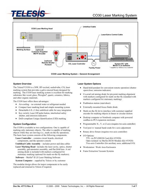
<strong>System</strong> Software<br />
The powerful <strong>Telesis</strong> Merlin II LS <strong>Laser</strong> <strong>Marking</strong> Software is a<br />
Windows ® based software package that comes standard with the<br />
laser marking system. It is a graphical user interface that makes<br />
marking pattern design quick and easy. The WYSIWYG (whatyou-see-is-what-you-get)<br />
interface provides a to-scale image of<br />
the pattern as it is created. Just “click and drag” for immediate<br />
adjustment to field size, location, or orientation.<br />
The Merlin II LS includes tools to create and edit text (at any<br />
angle), arc text, rectangles, circles, ellipses, and lines. Multiple<br />
fields may be grouped and saved as a block to form a logo.<br />
Existing DXF files can also be imported for marking. Nonprintable<br />
fields can be created to clearly display a graphical<br />
representation of the part being marked.<br />
Overview of Merlin-II LS User Interface<br />
Merlin II LS <strong>Laser</strong> <strong>Marking</strong> Software Specifications<br />
Operating <strong>System</strong> ..................Windows ® 2000, Windows ® XP, or<br />
Windows ® Vista Business using a<br />
Desktop PC or Notebook PC<br />
Font Generation.....................True Type Fonts<br />
Barcodes and Matrix .............2D Data Matrix, PDF417, BC 39,<br />
Interleaved 2 of 5, UPCA/UPCE BC<br />
128, Maxi Code, Code 93, QR Code<br />
and others<br />
Graphic Formats....................Raster and Vector: BMP, GIF, JPG,<br />
WMF, EMF, DXF, CUR, ICO<br />
Serialization...........................Automatic and Manual Input<br />
Host Interface Capable<br />
Linear <strong>Marking</strong>......................Scalable with Letter Spacing<br />
Control<br />
Arc Text <strong>Marking</strong>..................Scalable and Adjustable<br />
Drawing Tools.......................Line, Rectangle, Circle, Ellipse<br />
Doc No. 47713 Rev. E 5 of 7
Remote Communications<br />
The communication capability of the marking system software<br />
allows you to control the laser from remote I/O devices. Remote<br />
communications can be performed by connecting to a Host computer,<br />
an optional I/O card, or an optional two-axis Auxiliary Controller.<br />
The rear panel of the controller also provides a connector to<br />
monitor output signals that report the status of the shutter, laser<br />
emission, and fault conditions.<br />
Host Communications. Remote communications may be<br />
executed from a host computer using RS-232 or Ethernet<br />
(TCP/IP) connections to the system computer (i.e., the PC<br />
running the <strong>Telesis</strong> laser marking software). The software<br />
provides parameters to define the data transmitted to and from<br />
the host. For more information on using and configuring these<br />
parameters, refer to the Operation Manual supplied with the<br />
laser marking software.<br />
I/O Card. <strong>Telesis</strong> offers an optional I/O card that provides six<br />
input signals (Start Print, Abort, and four programmable inputs)<br />
and six output signals (Ready, Done, Paused, and three<br />
programmable outputs). The I/O card is available in the<br />
following kits. For more information on using the optional I/O<br />
card, refer to the <strong>Telesis</strong> Optional I/O Card Installation<br />
Supplement supplied in each of these kits.<br />
Kit #53920 This kit is available for all <strong>Telesis</strong> laser<br />
systems. It includes the I/O Card, SIPs resistor packs<br />
(pre-installed), the software driver CD, and installation<br />
documentation.<br />
This kit does not provide opto-isolated signals. If this kit<br />
is used, it is the responsibility of the installer/integrator<br />
to provide opto-isolation between remote I/O devices<br />
and the I/O card. Refer to the OEM User’s Guide for<br />
signal limitations.<br />
Note: <strong>Telesis</strong> does not endorse direct connection of<br />
I/O signals to the I/O card. Direct connections<br />
to high current/high voltage devices will<br />
damage the card.<br />
Kit #53928 This kit is available for all laser systems that<br />
use the Merlin-II LS <strong>Laser</strong> <strong>Marking</strong> Software. It<br />
includes Kit #53920 (above), plus the <strong>Telesis</strong> I/O<br />
Interface Module and two cable assemblies.<br />
This kit provides opto-isolated signals between remote<br />
I/O devices and the I/O card through the <strong>Telesis</strong> I/O<br />
Interface Module. Additional opto-isolator board<br />
assemblies or opto-isolated I/O rack assemblies are not<br />
required when the interface module is used.<br />
Two-axis Controller. <strong>Telesis</strong> offers an optional two-axis<br />
controller for all laser systems that use the Merlin-II LS <strong>Laser</strong><br />
<strong>Marking</strong> Software. The auxiliary controller provides an<br />
interface for connecting six input and six output signals to and<br />
from the laser marking system, and for connecting the optional<br />
auxiliary axes: vertical (Z) axis, rotational (Theta) axis, and<br />
linear (L1 and L2) axes.<br />
Environmental considerations must be taken into account when<br />
installing the auxiliary controller concerning contaminants and<br />
EMI susceptibility. For details, refer to the Installation/<br />
Maintenance Manual supplied with the controller.<br />
<strong>CO30</strong> <strong>Laser</strong> <strong>Marking</strong> <strong>System</strong><br />
Communications Protocol<br />
Two types of host interface are supported (RS-232 or TCP/IP) and<br />
two communication protocols are provided through the Merlin-II<br />
LS marking system software (Programmable and Extended).<br />
Programmable Protocol. Programmable protocol provides oneway<br />
(receive only) communication with no error checking or<br />
acknowledgment of the transmitted data. You may use<br />
Programmable protocol to extract a continuous portion of a<br />
message string to print. This can be used with a host computer or a<br />
bar code scanner. Note that XON/XOFF Protocol applies even<br />
when Programmable Protocol is selected.<br />
The Programmable Protocol Message Type identifies the type of<br />
message sent from the host. It determines how the marker uses the<br />
data it extracts from the host message string when Programmable<br />
Protocol is used.<br />
49 Message type 49 ("1") overwrites the content of the first<br />
text-based field in the pattern with the data extracted from<br />
the host message. Note that if the field contains message<br />
flags, they will be overwritten, not updated.<br />
65 Message type 65 ("A") updates the Offset Angle parameter<br />
with the data extracted from the host message. Syntax for<br />
the transmitted string is ±n where ± is a positive or<br />
negative sign and n is an integer that represents the offset<br />
angle for the marking window.<br />
72 Message type 72 ("H") updates the Offset X/Y parameters<br />
with the data extracted from the host message. Syntax for<br />
the transmitted string is ±X.X,±Y.Y where ± is a positive<br />
or negative sign, X.X represents the X-axis offset distance,<br />
and Y.Y represents the Y-axis offset distance.<br />
80 Message type 80 ("P") indicates the data extracted from the<br />
host message is the name of the pattern to be loaded.<br />
81 Message type 81 ("Q") updates the text in the first query<br />
text buffer (buffer 0) with the data extracted from the host<br />
message.<br />
86 Message type 86 ("V") updates the text in the first variable<br />
text field in the pattern with the data extracted from the<br />
host message.<br />
118 Message type 118 ("v") updates the first text field<br />
encountered in the pattern that contains a variable text flag<br />
that matches the specified string length.<br />
If the host is providing the Message Type within the transmitted<br />
text string, enter "0" in the Message Type parameter text box<br />
displayed on the Programmable tab of the Host/Setup window.<br />
0 Message type 0 (zero) indicates that the host will provide<br />
the message type, field number (if applicable), and data (if<br />
applicable). This option allows more flexibility by<br />
delegating the message type selection to the host on a<br />
message-by-message basis. It also allows you to direct data<br />
to specific fields and/or query text buffers.<br />
The host can use Message Type 0 to provide data to the<br />
marking system. The marking system will insert data<br />
transmitted with the message into the appropriate location.<br />
Doc No. 47713 Rev. E 6 of 7
Communications Protocol (continued)<br />
Extended Protocol. Extended protocol provides two-way<br />
communication with error checking. It is designed to provide<br />
secure communications with an intelligent host device using predefined<br />
message formats and response formats. It also provides<br />
error checking using a block check code to detect faults in the<br />
transmitted messages and to verify the data is properly received.<br />
The Extended Protocol Message Type determines how the marker<br />
uses the data it extracts from the host message string or from the<br />
marking system software, as applicable.<br />
1 Message Type "1" can provide data to a text string in the<br />
pattern or poll the pattern for data.<br />
A Message Type "A" can provide data to the system Offset<br />
Angle parameter for the marking window or poll the system<br />
for data.<br />
E Message Type "E" allows the host to take the machine<br />
offline. It also provides the option of displaying an error<br />
message box with the provided data string.<br />
V Message Type "V" can provide data to a variable text string<br />
in the pattern or poll the pattern for data.<br />
P Message Type "P" can load a pattern or poll the system for<br />
the current pattern name.<br />
O Message Type "O" places the marker online. This allows a<br />
host computer to reset. For example, this may be used to<br />
recover from a power outage when the marker is<br />
unattended.<br />
G Message Type "G" initiates a print cycle.<br />
Q Message Type "Q" can provide data to the system query text<br />
buffer or poll the system for data.<br />
H Message Type "H" can provide data to the system X/Y<br />
Offset parameters or poll the system for data.<br />
S Message Type "S" is used to poll the system for the machine<br />
status. The machine status is returned to the host in an eightcharacter<br />
hexadecimal mask.<br />
I Message Type "I" is used to poll the system for the I/O<br />
status.<br />
TRADEMARKS<br />
<strong>Telesis</strong> and Merlin are registered trademarks of <strong>Telesis</strong><br />
<strong>Technologies</strong>, <strong>Inc</strong>. in the United States and/or other countries.<br />
Pentium is a registered trademark of Intel Corporation in the<br />
United States and other countries.<br />
Plexiglas is a registered trademark of Arkema, <strong>Inc</strong>.<br />
Vista is a trademark of Microsoft Corporation in the United States<br />
and other countries.<br />
Windows is a registered trademark of Microsoft Corporation in<br />
the United States and other countries<br />
<strong>CO30</strong> <strong>Laser</strong> <strong>Marking</strong> <strong>System</strong><br />
Doc No. 47713 Rev. E 7 of 7