TMP6100/400 SPECIFICATION SHEET
TMP6100/400 SPECIFICATION SHEET
TMP6100/400 SPECIFICATION SHEET

Create successful ePaper yourself
Turn your PDF publications into a flip-book with our unique Google optimized e-Paper software.
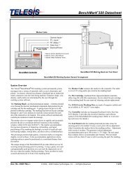
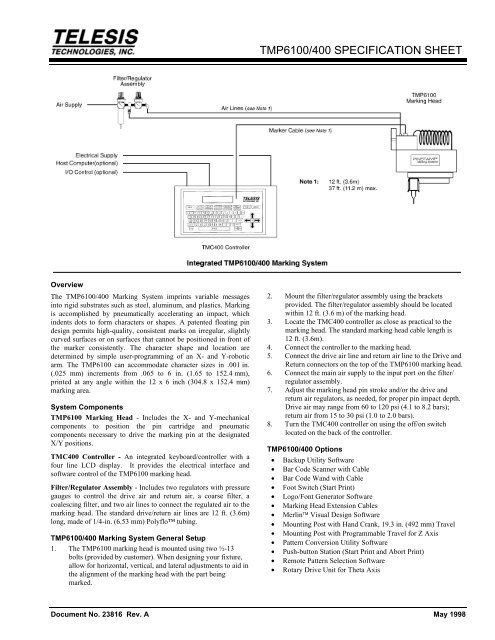
Overview<br />
The <strong>TMP6100</strong>/<strong>400</strong> Marking System imprints variable messages<br />
into rigid substrates such as steel, aluminum, and plastics. Marking<br />
is accomplished by pneumatically accelerating an impact, which<br />
indents dots to form characters or shapes. A patented floating pin<br />
design permits high-quality, consistent marks on irregular, slightly<br />
curved surfaces or on surfaces that cannot be positioned in front of<br />
the marker consistently. The character shape and location are<br />
determined by simple user-programming of an X- and Y-robotic<br />
arm. The <strong>TMP6100</strong> can accommodate character sizes in .001 in.<br />
(.025 mm) increments from .065 to 6 in. (1.65 to 152.4 mm),<br />
printed at any angle within the 12 x 6 inch (304.8 x 152.4 mm)<br />
marking area.<br />
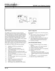
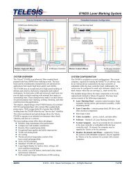
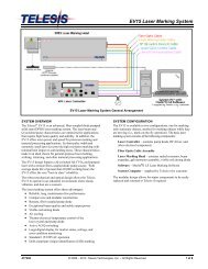
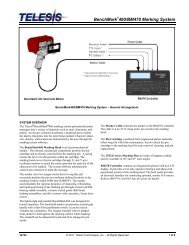
System Components<br />
<strong>TMP6100</strong> Marking Head - Includes the X- and Y-mechanical<br />
components to position the pin cartridge and pneumatic<br />
components necessary to drive the marking pin at the designated<br />
X/Y positions.<br />
TMC<strong>400</strong> Controller - An integrated keyboard/controller with a<br />
four line LCD display. It provides the electrical interface and<br />
software control of the <strong>TMP6100</strong> marking head.<br />
Filter/Regulator Assembly - Includes two regulators with pressure<br />
gauges to control the drive air and return air, a coarse filter, a<br />
coalescing filter, and two air lines to connect the regulated air to the<br />
marking head. The standard drive/return air lines are 12 ft. (3.6m)<br />
long, made of 1/4-in. (6.53 mm) Polyflo tubing.<br />
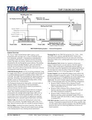
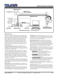
<strong>TMP6100</strong>/<strong>400</strong> Marking System General Setup<br />
1. The <strong>TMP6100</strong> marking head is mounted using two ½-13<br />
bolts (provided by customer). When designing your fixture,<br />
allow for horizontal, vertical, and lateral adjustments to aid in<br />
the alignment of the marking head with the part being<br />
marked.<br />
<strong>TMP6100</strong>/<strong>400</strong> <strong>SPECIFICATION</strong> <strong>SHEET</strong><br />
2. Mount the filter/regulator assembly using the brackets<br />
provided. The filter/regulator assembly should be located<br />
within 12 ft. (3.6 m) of the marking head.<br />
3. Locate the TMC<strong>400</strong> controller as close as practical to the<br />
marking head. The standard marking head cable length is<br />
12 ft. (3.6m).<br />
4. Connect the controller to the marking head.<br />
5. Connect the drive air line and return air line to the Drive and<br />
Return connectors on the top of the <strong>TMP6100</strong> marking head.<br />
6. Connect the main air supply to the input port on the filter/<br />
regulator assembly.<br />
7. Adjust the marking head pin stroke and/or the drive and<br />
return air regulators, as needed, for proper pin impact depth.<br />
Drive air may range from 60 to 120 psi (4.1 to 8.2 bars);<br />
return air from 15 to 30 psi (1.0 to 2.0 bars).<br />
8. Turn the TMC<strong>400</strong> controller on using the off/on switch<br />
located on the back of the controller.<br />
<strong>TMP6100</strong>/<strong>400</strong> Options<br />
• Backup Utility Software<br />
• Bar Code Scanner with Cable<br />
• Bar Code Wand with Cable<br />
• Foot Switch (Start Print)<br />
• Logo/Font Generator Software<br />
• Marking Head Extension Cables<br />
• Merlin Visual Design Software<br />
• Mounting Post with Hand Crank, 19.3 in. (492 mm) Travel<br />
• Mounting Post with Programmable Travel for Z Axis<br />
• Pattern Conversion Utility Software<br />
• Push-button Station (Start Print and Abort Print)<br />
• Remote Pattern Selection Software<br />
• Rotary Drive Unit for Theta Axis<br />
Document No. 23816 Rev. A May 1998
<strong>TMP6100</strong>/<strong>400</strong> <strong>SPECIFICATION</strong> <strong>SHEET</strong><br />
<strong>TMP6100</strong> Marking Head Specifications<br />
Marking Area 12.0 x 6.0 in. (304.8 x 152.4 mm)<br />
Marking Speed 2 characters per second<br />
Air Supply Clean and dry, 60 to 120 psi (4.1 to 8.3 bars)<br />
80 psi (5.5 bars) minimum recommended<br />
Air Consumption 0.3 SCFM (idle); 1.5 SCFM (marking)<br />
Air Inlet Pressure 60 to 120 psi (4.1 to 8.3 bars) dependent on<br />
marking force<br />
Operating Temp. 32° to 104°F (0° to 40°C) non-condensing<br />
Weight 16.8 lb. (7.6 Kg) not including support tooling<br />
Pin Types 25-, 25XL-, 101-, or 150S-series<br />
Pin Material Powdered Metal or Carbide<br />
(25- and 101-series)<br />
Powdered Metal or Carbide-tipped<br />
(150S-series)<br />
<strong>TMP6100</strong> Marking Head Components<br />
<strong>TMP6100</strong> X-Y Mechanicals - The <strong>TMP6100</strong> marking head is an<br />
X- and Y-robotic mechanism which uses stepper motors to<br />
independently drive its A- and B-arms. This design provides a<br />
generous 12 x 6 in. (304.8 x 152.4 mm) marking window. The<br />
<strong>TMP6100</strong> accurately and rapidly positions the pin cartridge at<br />
coordinate-defined locations to within .002 in. (0.051 mm) of any<br />
point in the window.<br />
Marking Pins - Four pin types are available for the <strong>TMP6100</strong>: the<br />
25-, 25XL-, 101-, and 150S-series. Refer to the illustration (above)<br />
for maximum pin extension (pin stroke). Refer to the marking depth<br />
tables for pin cone angles and depths.<br />
2<br />
Pin Cartridge - Lightweight pin cartridges are provided for the 25,<br />
25XL, and 150S-series marking pins. Machined from a plastic<br />
material, the marking pin cartridge offers long life with little<br />
maintenance. The 101-series pins use an aluminum cartridge with a<br />
Duralon ® sleeve. These cartridge configurations eliminate the need<br />
for pin lubrication. Clasps are used to attach the pin cartridge to<br />
the marking head for easy pin replacement.<br />
Electrical Cable - Connects the marking head to the controller. The<br />
head cable is a highly flexible cable. The standard cable length is<br />
12 ft. (3.6 m). Cable extensions are available for distances of up to<br />
37 ft. (11.2 m).<br />
<strong>TMP6100</strong> Marking Characteristics<br />
Marking - Marking is accomplished by indenting dots into the<br />
product using a pneumatically accelerated and returned impact pin.<br />
Characters and shapes can be produced at any angle with<br />
resolutions from 10 dots per inch to 200 dots per inch for an<br />
engraved look. The depth of mark can be adjusted over a<br />
significant range by adjusting the pin stroke (extension) and, to a<br />
lesser extent, by adjusting the drive air pressure.<br />
Marking Speeds - Generally the system will mark two characters<br />
per second. Speeds will vary slightly depending on the selected<br />
character size, style, and dot density. Specific marking times can be<br />
verified by a Telesis representative.
Pin Life - Pin life depends largely on the type of material being<br />
marked, how hard or abrasive it is, and the required marking depth.<br />
On typical metals with a hardness of Rockwell Rb47, at a depth of<br />
.005 in. (.127 mm), powdered steel pins average about 3 million<br />
impressions before needing sharpened; carbide pins average<br />
approximately 9 million impressions. If carbide pins are used,<br />
marking times will increase by approximately 25% due to the<br />
increased weight of the pins<br />
Noise - All <strong>TMP6100</strong> Marking Systems are equipped with mufflers<br />
on the solenoid exhaust to reduce noise. Although every attempt is<br />
made to reduce noise, the material being marked influences the<br />
noise level significantly. For example, marking a lead block<br />
produces less noise than marking a thin-walled steel pipe.<br />
Marking Depth - The following tables provide sample marking<br />
depths using different materials marked with various pin types and<br />
cone (tip) angles. Drive air was set at 80 psi (5.52 bars) and Return<br />
air was set at 20 psi (1.38 bars). The pin stroke was set to the<br />
maximum allowable distance for each pin type to achieve the<br />
maximum depth of mark (i.e., 0.5-in. (12.7 mm) for 25-series pins,<br />
0.5-in (12.7 mm) for 101 pins, and 0.25-in. (6.4 mm) for 150S<br />
pins).<br />
Marking Depths Using Type 25 Powdered-Metal Pin<br />
MATERIAL<br />
(HARDNESS)<br />
Aluminum<br />
(Rb2)<br />
Brass<br />
(Rb22)<br />
Cast Iron<br />
(Rb47)<br />
Cold Rolled<br />
Steel (Rb53)<br />
MATERIAL<br />
(HARDNESS)<br />
Aluminum<br />
(Rb2)<br />
Brass<br />
(Rb22)<br />
Cast Iron<br />
(Rb47)<br />
Cold Rolled<br />
Steel (Rb53)<br />
MATERIAL<br />
(HARDNESS)<br />
Aluminum<br />
(Rb2)<br />
Brass<br />
(Rb22)<br />
Cast Iron<br />
(Rb47)<br />
Cold Rolled<br />
Steel (Rb53)<br />
22°<br />
CONE<br />
0.0040 in<br />
0.1016 mm<br />
0.0025 in<br />
0.0635 mm<br />
0.0025 in<br />
0.0635 mm<br />
0.0025 in<br />
0.0635 mm<br />
30°<br />
CONE<br />
0.0045 in<br />
0.1143 mm<br />
0.0030 in<br />
0.0762 mm<br />
0.0030 in<br />
0.0762 mm<br />
0.0030 in<br />
0.0762 mm<br />
45°<br />
CONE<br />
0.0080 in<br />
0.2032 mm<br />
0.0055 in<br />
0.1397 mm<br />
0.0055 in<br />
0.1397 mm<br />
0.0055 in<br />
0.1397 mm<br />
Marking Depths Using Type 25 Carbide Pin<br />
22°<br />
CONE<br />
0.0040 in<br />
0.1016 mm<br />
0.0025 in<br />
0.0635 mm<br />
0.0025 in<br />
0.0635 mm<br />
0.0025 in<br />
0.0635 mm<br />
30°<br />
CONE<br />
0.0050 in<br />
0.1270 mm<br />
0.0035 in<br />
0.0889 mm<br />
0.0035 in<br />
0.0889 mm<br />
0.0035 in<br />
0.0889 mm<br />
45°<br />
CONE<br />
0.0080 in<br />
0.2032 mm<br />
0.0060 in<br />
0.1524 mm<br />
0.0060 in<br />
0.1524 mm<br />
0.0060 in<br />
0.1524 mm<br />
Marking Depths Using Type 101 or 150S Pin<br />
30°<br />
CONE<br />
0.0110 in<br />
0.2794 mm<br />
0.0080 in<br />
0.2032 mm<br />
0.0060 in<br />
0.1524 mm<br />
0.0060 in<br />
0.1524 mm<br />
45°<br />
CONE<br />
0.0150 in<br />
0.3810 mm<br />
0.0120 in<br />
0.3048 mm<br />
0.0100 in<br />
0.2540 mm<br />
0.0100 in<br />
0.2540 mm<br />
* Denotes Carbide Pin (all other 150S-Powdered Metal)<br />
45°<br />
CONE *<br />
0.0170 in<br />
0.4318 mm<br />
0.0135 in<br />
0.3429 mm<br />
0.0115 in<br />
0.2921 mm<br />
0.0110 in<br />
0.2794 mm<br />
60°<br />
CONE<br />
0.0110 in<br />
0.2794 mm<br />
0.0080 in<br />
0.2032 mm<br />
0.0080 in<br />
0.2032 mm<br />
0.0080 in<br />
0.2032 mm<br />
60°<br />
CONE<br />
0.0065 in<br />
0.1651 mm<br />
0.0040 in<br />
0.1016 mm<br />
0.0040 in<br />
0.1016 mm<br />
0.0040 in<br />
0.1016 mm<br />
60°<br />
CONE<br />
0.0220 in<br />
0.5588 mm<br />
0.0160 in<br />
0.4064 mm<br />
0.0115 in<br />
0.3937 mm<br />
0.0150 in<br />
0.3810 mm<br />
<strong>TMP6100</strong>/<strong>400</strong> <strong>SPECIFICATION</strong> <strong>SHEET</strong><br />
TMC<strong>400</strong> Controller<br />
The TMC<strong>400</strong> includes an integrated keyboard with a four-line LCD<br />
display, a marking head connector, an input/output connector and a<br />
serial interface. The I/O connector is used for START PRINT,<br />
ABORT, READY and DONE signals to/from a PLC or other DC<br />
I/O signals. The serial interface connector is used for RS232/485<br />
communications with serial devices such as a host computer or bar<br />
code scanner. Up to 31 TMC<strong>400</strong>s may be used in a multi-drop<br />
configuration using the RS-485 interface. Once the system is setup,<br />
a host computer can load patterns, download messages, take the<br />
marker on and offline, and monitor system errors. Optional PC<br />
interface software allows you to remotely setup and control the<br />
marker through a personal computer (PC). The utilities provide<br />
small, DOS command line executables to be called by other<br />
programs for marker control. The PC software also provides a user<br />
interface to design, backup, and restore patterns.<br />
Specifications<br />
Operating Temp. 32° to 105° F (0°-40°C), non-condensing<br />
Weight 9.5 lb. (4.32 Kg)<br />
Power Requirements 95-130 VAC, 2 amps, 50-60 Hz single phase<br />
200-250 VAC, 1 amp, 50-60 Hz single phase<br />
I/O Voltage 12 to 24 VDC (customer-supplied)<br />
I/O Control Signals<br />
As an option to local keyboard control, the <strong>TMP6100</strong> can be<br />
remotely controlled through an I/O connector on the back of the<br />
controller. The TMC<strong>400</strong> is configured for DC I/O only. A cable<br />
connector (with pins) is supplied for customer wiring of an I/O<br />
cable.<br />
START PRINT Input signal, begins print cycle<br />
ABORT Input signal, aborts print cycle<br />
READY Output signal, ready for message or start print<br />
DONE Output signal, print cycle complete<br />
OUTPUT COMM Both READY and DONE<br />
INPUT COMM Both START PRINT and ABORT<br />
3
<strong>TMP6100</strong>/<strong>400</strong> <strong>SPECIFICATION</strong> <strong>SHEET</strong><br />
Serial Communications<br />
The TMC<strong>400</strong> controller has one DB25 serial port for either RS232<br />
or RS485 communication. The RS232 interface is most often used<br />
with remote devices such as Bar Code Readers or Host Computers.<br />
The RS485 interface is normally used for long transmission<br />
distances or multi-drop networks of up to 31 TMC<strong>400</strong> controllers.<br />
Communications Protocols<br />
The TMC<strong>400</strong> serial port may be configured to communicate with a<br />
remote device using either the Telesis Programmable or Extended<br />
Protocol. The following describes the serial data character format<br />
on all transmissions to and from the TMC<strong>400</strong> controller.<br />
• RS-232<br />
• Asynchronous<br />
• 1200, 2<strong>400</strong>, 4800, 9600, or 19200 baud-host<br />
• One Start Bit<br />
• One or Two Stop Bit(s)<br />
• Seven or Eight Data Bits<br />
• None, Even or Odd Parity<br />
Programmable Protocol. Programmable Protocol is used where<br />
very simple one-way communications are required (such as with bar<br />
code scanners). Programmable Protocol provides no error checking<br />
or acknowledgment of the transmitted data. Note: XON/XOFF<br />
Protocol applies even when Programmable Protocol is selected.<br />
Starting Character – specifies where the software begins to<br />
count character positions. This number must be entered in ASCII<br />
decimal format such as 2 for STX.<br />
Terminating Character – identifies the end of transmitted string<br />
(usually a carriage return, i.e., CR-ASCII, decimal 13).<br />
Character Position – counted from the starting character<br />
ignoring all characters preceding it.<br />
Character Length – accepts variable length messages (if set<br />
to 0) or messages of a pre-specified, fixed number of characters.<br />
Ignore Character – identifies the character to ignore when sent<br />
from the host (usually a line feed, LF-ASCII, decimal 10).<br />
Message Type – enables characters to be extracted from data<br />
transmitted from the host. Programmable Protocol supports three<br />
message types: I, V, and P. Refer to Extended Protocol for an<br />
explanation of these message types.<br />
Extended Protocol. Extended Protocol includes error checking and<br />
transmission acknowledgment. It should be used in applications<br />
where serial communication is a vital part of the marking operation.<br />
Extended Protocol must be used in multi-drop applications. All<br />
communications are carried out in a master-slave relationship with<br />
the host being the master. Only the master has the ability to initiate<br />
communications. If the host does not receive a response within<br />
three seconds, it should re-transmit its original message. If no<br />
response is received after three tries, it should declare the link to be<br />
down. The following describes the message format as sent from the<br />
master to the TMC<strong>400</strong> controller.<br />
4<br />
SOH TYPE [##] STX [DATA TEXT] ETX BCC CR<br />
where:<br />
SOH ASCII Start of Header character (001H). The controller<br />
ignores all characters received prior to the SOH.<br />
TYPE A single, printable ASCII character that defines the<br />
meaning (type) and content of the message downloaded from the<br />
host, where:<br />
1 overwrites a text field of the currently loaded pattern<br />
V updates a variable text field of the currently loaded pattern<br />
P specifies a pattern name to be loaded for printing<br />
O resets the marker and places it online<br />
G initiates a print cycle to mark the currently loaded pattern<br />
I polls the input status of GO signal and spare input signals;<br />
polls the output status of READY and DONE signals.<br />
[##] Two optional ASCII decimal digits that specify the Station<br />
ID number for use in multi-drop network applications. The ID<br />
may range from 00-31. Note: "00" is reserved for applications<br />
where only one controller is used. In such applications, this field<br />
may be eliminated and "00" will be assumed.<br />
STX ASCII Start of Text Character (002H).<br />
[DATA TEXT] Optional field that may be required for certain<br />
message types.<br />
ETX ASCII end of text character (003H).<br />
BCC Optional Block Check Code that is generated and sent to<br />
improve link reliability by providing fault detection. The BCC is<br />
calculated by taking an eight bit addition of the TYPE and DATA<br />
TEXT characters and transmitting them as a three digit ASCII<br />
decimal number in the range from 000 to 255. If the sum is greater<br />
than 255, the most significant bit overflows and is discarded.<br />
CR ASCII Carriage Return Character (00DH).<br />
System Software<br />
Installed within the TMC<strong>400</strong> controller, the system software<br />
provides the Operator’s interface to marking system. Users can<br />
create and store information to be printed. The way information is<br />
organized and presented is called a pattern. Individual parts of a<br />
pattern are called fields. Each field is unique and allows the user to<br />
specify information such as its X and Y location, character size,<br />
font style, and special features like auto serialization, date codes, or<br />
shift codes. Once the system is setup, a host computer can load<br />
patterns, download messages, place the marker on and offline, and<br />
monitor system errors.<br />
Message Flags<br />
Certain “flags” may be included in the text to automatically insert<br />
data at the location of the flag within the pattern field. For example:<br />
%C Date and Time (MM/DD/YY HH:MM)<br />
%F Single-digit checksum for PSOCR ®<br />
%J Julian Day of the Year (001 - 365)<br />
%R Week number of the year.<br />
%#S Serial Number Insertion<br />
%#V Variable Text Insertion (padded with spaces)<br />
User Parameters. Define shift starting times, user shift codes,<br />
single character year tables, and single character month tables.<br />
%E User Year Code<br />
%U User Month Code<br />
%Z User Shift Code