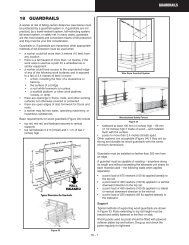
Construction Health and Safety Manual - Ch.24 Rigging
Construction Health and Safety Manual - Ch.24 Rigging
Construction Health and Safety Manual - Ch.24 Rigging
- No tags were found...

You also want an ePaper? Increase the reach of your titles
YUMPU automatically turns print PDFs into web optimized ePapers that Google loves.
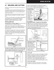
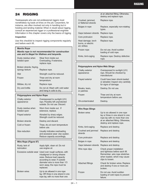
RIGGING24 RIGGINGTradespeople who are not professional riggers mustnonetheless rig loads at times on the job. Carpenters, forinstance, are often involved not only in h<strong>and</strong>ling but inhoisting <strong>and</strong> l<strong>and</strong>ing material. When in doubt about rigging,consult an experienced rigger or a professional engineer.Information in this chapter covers only the basics of rigging.InspectionUse this checklist to inspect rigging components regularly<strong>and</strong> before each lift.Manila RopeManila rope is not recommended for constructionuse <strong>and</strong> is illegal for lifelines <strong>and</strong> lanyards.Dusty residue whentwisted openBroken str<strong>and</strong>s, fraying,spongy textureWetFrozenMildew, dry rotDry <strong>and</strong> brittleWear from inside out.Overloading. If extensive,replace rope.Replace rope.Strength could be reduced.Thaw <strong>and</strong> dry at roomtemperature.Replace rope.Do not oil. Wash with cold water<strong>and</strong> hang in coils to dry.Polypropylene <strong>and</strong> Nylon RopeChalky exterior Overexposed to sunlight (UV)appearancerays. Possibly left unprotectedoutside. Do not use. Discard.Dusty residue when Worn from inside out. Iftwisted open extensive, replace.Frayed exterior Abraded by sharp edges.Strength could be reduced.Broken str<strong>and</strong>s Destroy <strong>and</strong> discard.Cold or frozen Thaw, dry at room temperaturebefore use.Size reduction Usually indicates overloading<strong>and</strong> excessive wear. Use caution.Reduce capacity accordingly.Wire Rope (Figure 87)Rusty, lack of Apply light, clean oil. Do notlubricationuse engine oil.Excessive outside wear Used over rough surfaces, withmisaligned or wrong sheavesizes. Reduce load capacityaccording to wear. If outsidediameter wire is more than 1/3worn away, the rope must bereplaced.Broken wires Up to six allowed in one ropelay, OR three in one str<strong>and</strong> in onerope lay, with no more than oneCrushed, jammed,or flattened str<strong>and</strong>sBulges in ropeat an attached fitting. Otherwise,destroy <strong>and</strong> replace rope.Replace rope.Replace, especially non-rotatingtypes.Gaps between str<strong>and</strong>s Replace rope.Core protrusion Replace rope.Heat damage, torch Replace rope.burns, or electricarc strikesFrozen ropeDo not use. Avoid suddenloading of cold rope.Kinks, bird-caging Replace rope. Destroy defectiverope.Polypropylene <strong>and</strong> Nylon Web SlingsChalky exterior Overexposed to sunlight (UV)appearancerays. Should be checked bymanufacturer.Frayed exterior Could have been shock-loadedor abraded. Inspect very carefullyfor signs of damage.Breaks, tears, Destroy. Do not use.or patchesFrozenThaw <strong>and</strong> dry at roomtemperature before use.Oil-contaminated Destroy.Wire Rope SlingsBroken wiresKinks, bird-cagingCrushed <strong>and</strong> jammedstr<strong>and</strong>sUp to six allowed in one ropelay or three in one str<strong>and</strong> in onerope lay with no more than oneat an attached fitting. Otherwise,destroy <strong>and</strong> replace rope.Replace <strong>and</strong> destroy.Replace <strong>and</strong> destroy.Core protrusion Replace <strong>and</strong> destroy.Bulges in rope Replace <strong>and</strong> destroy.Gaps between str<strong>and</strong>s Replace <strong>and</strong> destroy.Wire rope clips Check proper installation<strong>and</strong> tightness before each lift.Remember, wire rope stretcheswhen loaded, which may causeclips to loosen.Attached fittings Check for broken wires. Replace<strong>and</strong> destroy if one or more arebroken.FrozenDo not use. Avoid suddenloading of cold ropes to preventfailure.24 – 1
RIGGINGSharp bendsAvoid sharp corners. Use padssuch as old carpet, rubber hose,or soft wood to prevent damage.Chain SlingsUse only alloy steel for overhead lifting.Elongated or Return to manufacturer forstretched links repair.Failure to hang straight Return to manufacturer forrepair.Bent, twisted, or Return to manufacturer forcracked links repair.Gouges, chips, Ground out <strong>and</strong> reduceor scorescapacity according to amountof material removed.Chain repairs are best left to the manufacturer. Chainbeyond repair should be cut with torch into short pieces.Estimate rope's condition at sectionshowing maximum deterioration.Core protrusion as a result oftorsional unbalance created byshock loading.WornSectionEnlargedView ofSingleStr<strong>and</strong>Where the surface wires areworn by 1/3 or more of theirdiameter, the rope must bereplaced.HardwareKnow what hardware to use, how touse it, <strong>and</strong> how its working loadlimits (WLLs) compare with the ropeor chain used with it.All fittings must be of adequatestrength for the application. OnlyReplace wire rope if there are– 6 or more broken wires in one lay– 3 or more broken wires in one str<strong>and</strong>in one lay– 3 or more broken wires in one lay inst<strong>and</strong>ing ropes.Protrusion of core resultingfrom shock loading.Multi-str<strong>and</strong> rope “bird cages” due totorsional unbalance. Typical of build-upseen at anchorage end of multi-fall craneapplication.A “bird cage” caused by sudden release oftension <strong>and</strong> resultant rebound of rope fromoverloaded condition. These str<strong>and</strong>s <strong>and</strong>wires will not return to their original positions.Figure 87 — Wire Rope InspectionFigure 88forged alloy steel load-rated hardware should be used foroverhead lifting. Load-rated hardware is stamped with itsWLL (Figure 88).Inspect hardware regularly <strong>and</strong> before each lift. Telltalesigns include– wear– cracks– severe corrosion– deformation/bends– mismatched parts– obvious damage.Any of these signsindicates a weakenedcomponent thatshould be replacedfor safety. Figure 89shows what to checkfor on a hook.Check forcracks <strong>and</strong>twisting.Sling ConfigurationsThe term “sling” includes a wide variety of configurationsfor all fibre ropes, wire ropes, chains,<strong>and</strong> webs. The most commonly usedtypes in construction are explained here.Single Vertical HitchThe total weight of the load is carried bya single leg. This configuration must notbe used for lifting loose material, longmaterial, or anything difficult to balance.This hitch provides absolutely no controlover the load because it permits rotation.Bridle HitchTwo, three, or four single hitchescan be used together to form abridle hitch. They provide excellentstability when the load is distributedequally among the legs, whenthe hook is directly over thecentre of gravity of the load, <strong>and</strong>the load is raised level. The leglength may need adjustmentwith turnbuckles to distribute theload.Single Basket HitchThis hitch is ideal for loads withinherent stabilizing characteristics.The load is automaticallyequalized, with each legsupporting half the load. Do notuse on loads that are difficultto balance because the loadcan tilt <strong>and</strong> slip out of the sling.Double Basket HitchConsists of two single basket hitchespassed under the load. The legs ofthe hitches must be kept far enoughapart to provide balance withoutopening excessive sling angles.Check for wear<strong>and</strong> deformation.Check for signsof opening up.Check for wear<strong>and</strong> cracks.Figure 89Hook Inspection AreasBridleHitchDetailSingleBasketHitch60° or moreSingleVerticalHitchCaution: Load maybe carried by only2 legs while 3rd<strong>and</strong> 4th merelybalance it.DoubleBasketHitch24 – 2
RIGGINGDouble Wrap Basket HitchA basket hitch that is wrapped completelyaround the load. This method is excellent forh<strong>and</strong>ling loose materials, pipes, rods, orsmooth cylindrical loads because the rope orchain exerts a full 360-degree contact withload <strong>and</strong> tends to draw it together.Single Choker HitchThis forms a noose in the rope <strong>and</strong>tightens as the load is lifted. It doesnot provide full contact <strong>and</strong> must notbe used to lift loose bundles or loadsdifficult to balance.Double Choker HitchConsists of two single chokersattached to the load <strong>and</strong> spread toprovide load stability. Does not grip theload completely but can balance theload. Can be used for h<strong>and</strong>ling loosebundles.Double Wrap Choker HitchThe rope or chain iswrapped completelyaround the load beforebeing hooked into thevertical part of the sling.Makes full contact with load <strong>and</strong>tends to draw it together. If thedouble wrap choker is incorrectlymade <strong>and</strong> the two eyes are placedon the crane hook, the supportinglegs of the sling may not be equal inlength <strong>and</strong> the load may be carriedby one leg only. Do not run the slingthrough the hook, permitting anunbalanced load to tip.Braided SlingsFabricated from six or eight smalldiameter ropes braided together toform a single rope that provides alarge bearing surface, tremendousstrength, <strong>and</strong> flexibility in alldirections. They are veryeasy to h<strong>and</strong>le <strong>and</strong> almostimpossible to kink. Especiallyuseful for basket hitcheswhere low bearing pressureis desirable or where thebend is extremely sharp.Metal (Wire or Chain)Mesh SlingsWell adapted for use whereloads are abrasive, hot, ortend to cut fabric or wire rope slings.Chain SlingsMade for abrasion <strong>and</strong> high temperatureresistance. The only chain suitable for liftingis grade 80 or 100 alloy steel chain. GradeDoubleWrapChokerHitchDoubleWrapBasketHitchSingleChokerHitchDoubleChokerHitchMetalMeshSlingsChainSlingsBraidedSlings80 chain is marked with an 8, 80, or 800. Grade 100 ismarked with a 10, 100, or 1000. The chain must beembossed with this grade marking every 3 feet or 20 links,whichever is shorter – although some manufacturers markevery link. Chain must be padded on sharp corners toprevent bending stresses.Wire Rope SlingsThe use of wire rope slings for lifting materials providesseveral advantages over other types of slings. While notas strong as chain, it has good flexibility with minimumweight. Outer wires breaking warn of failure <strong>and</strong> allowtime to react. Properly fabricated wire rope slings are verysafe for general construction use.On smooth surfaces, the baskethitch should be snubbedagainst a step or change ofcontour to prevent the ropefrom slipping as the load isapplied. The angle between theload <strong>and</strong> the sling should beapproximately 60 degrees orgreater to avoid slippage.On wooden boxes or crates, therope will dig into the woodsufficiently to prevent slippage. Onother rectangular loads, the ropeshould be protected by guards orload protectors at the edges toprevent kinking.60° or moreLoads should not be allowed toturn or slide along the rope during a lift. The sling or theload may become scuffed or damaged. Use a doublechoker if the load must turn.Hooking UpRIGHTWRONGLegs willslide together.To prevent slippage,keep angle 60° or more.• Avoid sharp bends, pinching, <strong>and</strong> kinks in riggingequipment. Thimbles should be used at all times insling eyes.• Never wrap a wire rope sling completely around ahook. The tight radius will damage the sling.• Make sure the load is balanced in the hook. Eccentricloading can reduce capacity dangerously.• Never point-load a hook unless it is designed <strong>and</strong>rated for such use (Figure 91).• Never wrap the crane hoist rope around the load.Attach the load to the hook by slings or other riggingdevices adequate for the load.• Avoid bending the eye section of wire rope slingsaround corners. The bend will weaken the splice orswaging.• Avoid bending wire rope slings near any attachedfitting.• Underst<strong>and</strong> the effect of sling angle on sling load(Figure 92) <strong>and</strong> pull angle on beam load (Figure 93).Rig the load with its centre of gravity directly below thehook to ensure stability. The crane hook should bebrought over the load's centre of gravity before the lift isstarted. Crane hook <strong>and</strong> load line should be verticalbefore lifting. Weights of common materials are listed inTables 7 to 11.24 – 3
RIGGINGFigure 91Point LoadingBestGoodCapacity Severely ReducedMinimumRecommendedAVOIDFigure 92Effect of Sling Angle on Sling LoadAngle of pull affects loadon beam.Figure 93Effect of Pull Angle on Beam LoadAngle Load onof Pull Beam90° 200 lbs60° 187 lbs 100 lbs45° 171 lbs90° 60° 45°Basic Knots <strong>and</strong> HitchesEvery worker should be able to tie thebasic knots <strong>and</strong> hitches that are usefulin everyday work.Round Turn <strong>and</strong> Two Half HitchesUsed to secure loads to behoisted horizontally. Two areusually required because theload can slide out if liftedvertically.Timber Hitch <strong>and</strong> Two HalfHitchesA good way to secure ascaffold plank for hoistingvertically. The timber hitch gripsthe load.Reef or Square KnotCan be used for tying tworopes of the same diametertogether. It is unsuitable for wetor slippery ropes <strong>and</strong> shouldbe used with caution since itTimberHitch<strong>and</strong> TwoHalfHitchesRound Turn<strong>and</strong> TwoHalf HitchesTwoHalfHitchesReef orSquare Knotunties easily when either free end is jerked. Both live <strong>and</strong>dead ends of the rope must come out of the loops at thesame side.Two Half HitchesTwo half hitches, which can be quickly tied, are reliable<strong>and</strong> can be put to almost any general use.24 – 4
RIGGINGRunning BowlineThe running bowline is mainly used for hanging objectswith ropes of different diameters. The weight of the objectdetermines the tension necessary for the knot to grip.Make an overh<strong>and</strong> loop with the end of the rope heldtoward you (1). Hold the loop with your thumb <strong>and</strong> fingers<strong>and</strong> bring the st<strong>and</strong>ing part of the rope back so that it liesbehind the loop (2). Take the end of the rope in behind thest<strong>and</strong>ing part, bring it up, <strong>and</strong> feed it through the loop (3).Pass it behind the st<strong>and</strong>ing part at the top of the loop <strong>and</strong>bring it back down through the loop (4).1 234WEIGHTS OF MATERIALS (Based On Volume)ApproximateApproximateWeightWeightMaterial Lbs. Per Material Lbs. PerCubic FootCubic FootMETALSTIMBER, AIR-DRYAluminum 165 Cedar 22Brass 535 Fir, Douglas, seasoned 34Bronze 500 Fir, Douglas, seasoned 40Copper 560 Fir, Douglas, wet 50Iron 480 Fir, Douglas, glue laminated 34Lead 710 Hemlock 30Steel 480 Pine 30Tin 460 Poplar 30MASONRY Spruce 28Ashlar masonry 140-160 LIQUIDSBrick masonry, soft 110 Alcohol, pure 49Brick masonry, common (about Gasoline 423 tons per thous<strong>and</strong>) 125 Oils 58Brick masonry, pressed 140 Water 62Clay tile masonry, average 60 EARTHRubble masonry 130-155 Earth, wet 100Concrete, cinder, taydite 100-110 Earth, dry (about 2050 lbs.)Concrete, slag 130 per cu. yd.) 75Concrete, stone 144 S<strong>and</strong> <strong>and</strong> gravel, wet 120Concrete, stone, reinforced S<strong>and</strong> <strong>and</strong> gravel, dry 105(4050 lbs. per cu. yd.) 150 River s<strong>and</strong> (about 3240 lbs.ICE AND SNOW per cu. yd.) 120Ice 56 VARIOUS BUILDINGSnow, dry, fresh fallen 8 MATERIALSSnow, dry, packed 12-25 Cement, portl<strong>and</strong>, loose 94Snow, wet 27-40 Cement, portl<strong>and</strong>, set 183MISCELLANEOUS Lime, gypsum, loose 53-64Asphalt 80 Mortar, cement-time, set 103Tar 75 Crushed rock (about 2565 lbs.Glass 160 per cu. yd.) 90-110Table 7Caution: This table contains sample values for the purposes of illustrationonly. Refer to the manufacturer of the material you’re using for precisevalues.BowlineNever jams or slipswhen properly tied. Itis a universal knot ifproperly tied <strong>and</strong>untied. Twointerlocking bowlinescan be used to jointwo ropes together.Single bowlines canbe used for hoistingor hitching directlyaround a ring orpost.Sheet BendCan be used fortying ropes of lightor medium size.Single Sheet BendRunning BowlineBowlineDouble Sheet Bend24 – 5DRYWALL WEIGHTSNon-Fire Rated 8' 10' 12'1/2" 58 lbs. 72 lbs. 86 lbs.5/8" 74 lbs. 92 lbs. 110 lbs.Fire-Rated1/2" 64 lbs. 80 lbs. 96 lbs.5/8" 77 lbs. 96 lbs. 115 lbs.Table 8Caution: This table contains sample values for the purposes of illustrationonly. Refer to the manufacturer of the material you’re using for precisevalues.STEEL STUDS AND TRIMS – WEIGHTSPcs./Bdl. Lbs. (perSTUD SIZE–.018 THICKNESS1,000 Lin. Ft.)1 5/8 All Lengths 10 2902 1/2 All Lengths 10 3403 5/8 All Lengths 10 4156 (.020) All Lengths 10 625TRACK SIZES–.018 THICKNESS1 5/8 Regular Leg 10 2402 1/2 Regular Leg 10 2953 5/8 Regular Leg 10 3656 (.020) Regular Leg 10 5701 5/8 2 Leg 12 3652 1/2 2 Leg 6 4153 5/8 2 Leg 6 470DRYWALL FURRING CHANNELElectro-Galvanized 10 300DRYWALL CORNER BEAD1 1/4 x 1 1/4 Various 120RESILIENT CHANNELElectro-Galvanized 20 210DRYWALL TRIMS1/2 Door & Windows L. 20 1005/8 Door & Window L. 20 1003/8 Casing Bead J. 20 1101/2 Casing Bead J. 20 1205/8 Casing Bead J. 20 130DRYWALL ANGLE1 x 2 Drywall Angle 10 200Table 9Caution: This table contains sample values for the purposes of illustrationonly. Refer to the manufacturer of the material or equipment you’re usingfor precise values.
RIGGINGWEIGHTS OF MATERIALS (Based On Surface Area)ApproximateApproximateWeightWeightMaterial Lbs. Per Material Lbs. PerSquare FootSquare FootCEILINGS(Per Inch of Thickness)Plaster boardAcoustic <strong>and</strong> fire resistive tilePlaster, gypsum-s<strong>and</strong>Plaster, light aggregatePlaster, cement s<strong>and</strong>ROOFINGThree-ply felt <strong>and</strong> gravelFive-ply felt <strong>and</strong> gravelThree-ply felt, no gravelFive-ply felt, no gravelShingles, woodShingles, asbestosShingles, asphaltShingles, 1/4 inch slateShingles, tilePARTITIONSSteel partitionsSolid 2" gypsum-s<strong>and</strong> plasterSolid 2" gypsum-light agg. plasterMetal studs, metal lath, 3/4"plaster both sidesMetal or wood studs, plasterboard <strong>and</strong> 1/2" plaster both sidesPlaster 1/2"Hollow clay tile 2 inch3 inch4 inch5 inch6 inchHollow slag concrete block 4 in6 inHollow gypsum block 3 inch4 inch5 inchSolid gypsum block6 inch2 inch3 inchMASONRY WALLS(Per 4 Inch of Thickness)BrickGlass brickHollow concrete blockHollow slag concrete blockHollow cinder concrete blockHollow haydite blockStone, averageBearing hollow clay tileTable 105284125.56.534232.51014420121818413161820252435101315.516.59.5134020302420225523FLOORING(Per Inch of Thickness)HardwoodSheathingPlywood, firWood block, treatedConcrete, finish or fillMastic baseMortar baseTerrazzoTile, vinyl 1/8 inchTile, linoleum 3/16 inchTile, cork, per 1/16 inchTile, rubber or asphalt 3/16 inchTile, ceramic or quarry 3/4 inchCarpetingDECKS AND SLABSSteel roof deck 1 1/2" - 14 ga.- 16 ga.- 18 ga.- 20 ga.- 22 ga.Steel cellular deck 1 1/2" - 12/12 ga.- 14/14 ga.- 16/16 ga.- 18/18 ga.- 20/20 ga.Steel cellular deck 3"- 12/12 ga.- 14/14 ga.- 16/16 ga.- 18/18 ga.- 20/20 ga.Concrete, reinforced, per inchConcrete, gypsum, per inchConcrete, lightweight, per inchMISCELLANEOUSWindows, glass, frameSkylight, glass, frameCorrugated asbestos 1/4 inchGlass, plate 1/4 inchGlass, commonPlastic sheet 1/4 inchCorrugated steel sheet, galv.- 12 ga.- 14 ga.- 16 ga.- 18 ga.- 20 ga.- 22 ga.Wood Joists - 16" ctrs. 2 x 122 x 102 x 8Steel plate (per inch of thickness)52.53412121012.51.510.521125432.521186.553.512.59.57.564.512.555-108123.53.51.51.55.5432.521.53.532.540Caution: This table contains sample values for the purposes ofillustration only. Refer to the manufacturer of the material you’re using forprecise values.HAND SIGNALS FOR HOISTING OPERATIONSLoad Up Load Down Load UpSlowly1Boom DownEverythingSlowlyTurn Left611Boom UpSlowlyUse WhipLineShortenHydraulic BoomBoom DownSlowlyUse MainLineExtendHydraulic Boom161718Close Clam Open Clam Dog Everything21271222<strong>Rigging</strong> <strong>Safety</strong> Tips381323Load DownSlowlyBoom UpLoad DownTravel ForwardBoom UpBoom DownLoad UpTurn RightSwing Load StopNo responseshould bemadeto unclearsignals.4914195101520SUSPENDED CEILING GRID SYSTEMS–WEIGHTSSystems Qty./Ctn. Lbs./Ctn.(Lin. Ft.) (Lbs.)NON-FIRE RATED GRID SYSTEM1 1/2 x 144" Main Runner 240 581 x 48" Cross Tee 300 551 x 24" Cross Tee 150 281 x 30" Cross Tee 187.5 351 x 20" Cross Tee 125 231 x 12" Cross Tee 75 14FIRE-RATED GRID SYSTEM1 1/2 x 144" Main Runner 240 701 1/2 x 48" Cross Tee 240 701 1/2" x 24" Cross Tee 120 35WALL MOULDINGSWall Mould 3/4 x 15/16 x 120" 400 49Reveal Mould 3/4 x 3/4 x 1/2 x 3/4 x 120" 200 36ACCESSORIESHold-Down Clips (for 5/8" tile) 500 pcs. 3BASKETWEAVE & CONVENTIONAL5' x 5' MODULE – NON RATED1 1/2 x 120" Main Member 200 491 1/2 x 60" Cross Tee 250 61Wall Mould 3/4 x 15/16 x 120" 400 57THIN LINE GRID SYSTEM – NON-RATEDMain Runner 1 1/2 x 144" 300 65Cross Tee 1 1/2 x 48" 300 65Cross Tee 1 1/2 x 24" 150 33Wall Mould 15/16 x 9/16 x 120" 500 62Reveal Mould 1 x 3/8 x 3/8 x 9/16 x 120" 300 48Main Runner 1 1/12 x 144" 300 65Cross Tee 1 1/2 x 48" 300 65Cross Tee 1 1/2 x 24" 150 33Wall Mount 15/16 x 9/16 x 120" 500 62Table 11Caution: This table contains sample values for the purposes ofillustration only. Refer to the manufacturer of the material or equipmentyou’re using for precise values.24 – 6With two or more slingson a hook, use a shackle.Block loose loads before unhooking.Stay back whenslings are pulled outfrom under loads.Use tag lines for control.Make sure loads are secure.
RIGGINGFor Cranes Operating “On Outriggers”For Crawler-Mounted Cranes or When Lifting “On Rubber”24 – 7