CAPACITORS - AMS Technologies
CAPACITORS - AMS Technologies
CAPACITORS - AMS Technologies
- No tags were found...
Create successful ePaper yourself
Turn your PDF publications into a flip-book with our unique Google optimized e-Paper software.
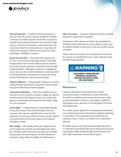
www.amstechnologies.comThermal Expansion — To allow for thermal expansion, atleast one end of the vacuum capacitor should have a flexibleconnection. In variable capacitors, the flexible connection isnormally made to the fixed electrode end. Avoid heavy rigidstraps or connections that produce a mechanical strain. Theconnections should be of substantial area to keep losses lowand provide cooling by conduction from both ends. Only asmall degree of flexibility is required.Electrical Connections — Both ends of the capacitor maybe “hot,” or one end may be grounded. Because of the highvoltages present, there must be sufficient clearance betweenthe vacuum capacitor and other components to prevent highvoltage breakdown. Although the capacitors are designed toensure optimum electrical field distribution, mounting shouldbe such that adjacent components do not upset this normalelectrical field and thus result in excessive heating.Magnetic Influences — Strong magnetic influences can induceheating and affect performance of capacitors. Electromagnetshave greater effect than permanent magnets.Transients and Parasitics — Where the possibility exists ofexternal arcs from transients or parasitic voltages, the capacitorshould be protected by adequate corona, or arc shields. Ballgaps are recommended when protection from simple voltagearc cover is required.Lead Lengths — At high frequencies, avoid long lead length,because the reactance of the strap will subtract from thereactance of the capacitor and effectively increase the totalcapacitance. In some cases, the total reactance may be reducedto the point where the minimum capacity of the capacitorwill appear too high.Side Loading — Side loading (radical force applied to leadscrew) will greatly accelerate wear and significantly reducelife. A flexible coupler connection to the lead screw is highlyrecommended. Increased frequency of 100% minimum tomaximum cycling will also be helpful. (See Maintenance.)Other Precautions — Capacitors should not be used as standoffinsulators to support heavy assemblies.Only the part of the capacitor specified as the mounting areashould be used for that purpose, and any clamps or straps mustbe attached carefully to avoid stress on the unit, possibly causingseal failure.Solder connections should not be made directly to the body ofthe capacitor, nor should there be any contact with the ceramicinsulator during operation.MaintenanceWARNINGDISCONNECT POWER BEFORESERVICING. HAZARDOUSVOLTAGE CAN SHOCK, BURNOR CAUSE DEATH.Capacitors operated at normal temperature in a cleanenvironment require no maintenance except to keep themfree of dirt accumulation and moisture that may cause a dropin external insulation resistance. A special glaze is applied toall Jennings ceramic capacitors to avoid absorption of moistureand foreign matter.For variable capacitor applications involving frequent adjustmentover a limited range, such as semiconductor impedance matching,it is advisable to cycle completely between minimum andmaximum at least 2 cycles every 10,000 cycles to redistributelubricant.If variable capacitors are being operated at high temperatures,it is advisable to periodically lubricate the shaft and bearing witha good grade of high temperature light oil and the lead screwwith a high temperature, extreme pressure grease.w w w . j e n n i n g s t e c h . c o m | 4 0 8 - 2 9 2 - 4 0 2 5 13


