TETRA in Tunnels - Anthony Sutton
TETRA in Tunnels - Anthony Sutton
TETRA in Tunnels - Anthony Sutton
- No tags were found...

Create successful ePaper yourself
Turn your PDF publications into a flip-book with our unique Google optimized e-Paper software.
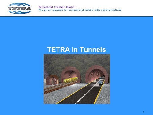
<strong>TETRA</strong> <strong>in</strong> <strong>Tunnels</strong>1
<strong>Anthony</strong> <strong>Sutton</strong>Sales Manager – Aerial Facilities Limitedanthonys@aerial.co.ukwww.aerialfacilities .com2
Tunnel Environments‣ Road <strong>Tunnels</strong>‣ Metros‣ Rail <strong>Tunnels</strong>‣ Underground service tunnels(Airports)Slide 3
Design Considerations - <strong>Tunnels</strong>‣ Length of Tunnel‣ Frequencies required <strong>in</strong> tunnel‣ Required signal strengths‣ Alarm<strong>in</strong>g‣ Redundancy‣ Method of coverage – LeakyFeeder Cable or antennas‣ Equipement Locations‣ External Signal StrengthsSlide 5
How to serve <strong>Tunnels</strong> - Antennas‣ Efficient for cover<strong>in</strong>g wideopen spaces‣ Poor <strong>in</strong> <strong>Tunnels</strong> at LowFrequency‣ Can Suffer from Near / Fareffect‣ Tuned to frequency bandSlide 6
How to serve <strong>Tunnels</strong> - Radiat<strong>in</strong>g Cable‣ Imperfectly screen co-axialcable with slots or holeswhich radiate‣ Controlled radiation, majorityof power transmitted alongthe cable‣ Avoids Near / Far Effect‣ Broadband or TunedSlide 7
Coverage <strong>in</strong> Tunnel - L<strong>in</strong>k Budget Calculations‣ Splitt<strong>in</strong>g Losses‣ Cable Longitud<strong>in</strong>al Losses‣ Coupl<strong>in</strong>g Loss‣ EquipmentPower/Sensitivity‣ Receive Signal Level‣ Propagation Loss (where iscoverage required?)Slide 8
Simple Road Tunnel CoverageDownl<strong>in</strong>k Signalstrength at Car =(+20dBm - longitud<strong>in</strong>alloss) – coupl<strong>in</strong>g loss:(+20 – 20dB(1000mtrs) – 75+40dBm-75dBm-75dBm100dB Free Space Loss (>5km @UHF)-60dBm= -75dBm at carantenna0dBm1km = 20dB Loss typLongitud<strong>in</strong>al Loss dB / km+20dBm+25dBm-35dBm-35dBm-55dBmCoupl<strong>in</strong>g Loss @ 95%: Typical 75dBCoupl<strong>in</strong>g loss 50% / 95% at distance 2m / 6m(75dB typical)-75dBmGa<strong>in</strong> 80dBTypical RX Sens = -113dBmTypical TX Pwr = +40dBmCar mobile transmit = +35dBmSlide 10
Coverage Options – Large <strong>Tunnels</strong> & Metros‣Direct Coverage from BTS– Direct connection• Can be dedicated tunnel coverage or alsoused to provide above ground coverage• Can also provide station coverage• Requires back haul l<strong>in</strong>k to networkSlide 13
Coverage Options – Large <strong>Tunnels</strong> & Metros‣Coverage from Cell Enhancer– Cascaded amplifiers• Low costs system• Easy to <strong>in</strong>stall• Lacks system redundancySlide 14
Coverage Options – Large <strong>Tunnels</strong> & Metros‣Coverage from Cell Enhancer– FO Back Bone• Low costs system• Easy to <strong>in</strong>stall• Improved system redundancySlide 15
Coverage Options – Large <strong>Tunnels</strong> & Metros‣Coverage from BTS & Cell Enhancer– Direct Feed – FO Mastersite• Improved performance• Easy to <strong>in</strong>stall• Utilise above ground BTS for undergroundcoverageFO MastesiteSlide 16
Coverage Options – Large <strong>Tunnels</strong> & Metros‣Coverage from Larger system with multiple BTS– Direct Feed – FO MastersiteSlide 17
Special Po<strong>in</strong>ts for Tetra‣ Time Delay is important if equi-signal overlap areasexist.‣ Two digital signals with differ<strong>in</strong>g delays cause symboloverlap. Demodulation uncerta<strong>in</strong>ty leads to high Bit ErrorRate.‣ Tim<strong>in</strong>g of overlapp<strong>in</strong>g signals should not differ by morethan about ¼ symbol period – less if possible.Zero Delay1/8 Symbol Delay1/4 Symbol Delay1/2 Symbol DelaySlide 19
What are Equi-signal overlaps‣Areas where BTS and repeatedsignals are both present.‣Tetra Symbol Rate is 18kbit/s or56uS/symbol‣Differential delay should be 56/4
Special Po<strong>in</strong>ts for Tetra‣ Propagation time <strong>in</strong> air is 3.3uS/km. In Fibre or <strong>in</strong> Cable it is1.5 times greater – practically 5uS/km. To avoid delayproblems <strong>in</strong> overlap areas differential route distance of thetwo signal components should not exceed 2.8km of fibre +cable.<strong>TETRA</strong> BS4km1.5kmFibre OpticSlave SiteFibre OpticMaster SiteCoupler -30dBFibre OpticSlave Site500m1km1km500m2km -1km = 1km OK4.5km - 1km = 3.5km NOKSlide 21
Alarm Monitor<strong>in</strong>g‣ Local Alarms for connection Scada system.‣ Remote from location direct to NMC‣ Remote alarm report<strong>in</strong>g back to MastersiteWESTMAINPLAZACITYEASTSOUTHHALLSlide 22
Key Features‣ Low cost‣ Limited visual impact‣ Seamless transitional coverage‣ High level of service availability‣ Expandable‣ Couple on to exist<strong>in</strong>g <strong>in</strong>frastructure or new build‣ S<strong>in</strong>gle or multiple bands / technologies on samesystemSlide 23
Sample of exist<strong>in</strong>g Tetra Tunnel Coverage‣ Madrid Metro‣ London Underground‣ Amsterdam Metro‣ Shanghai Metro‣ Blackwall Road Tunnel‣ Brussels Metro‣ Athens Metro‣ Moscow Metro‣ Channel Tunnel Rail L<strong>in</strong>k‣ Bilbao Metro‣ Dubai Airport – <strong>in</strong>clud<strong>in</strong>gservice tunnels‣ Barajas Tunnel – Road / Rail/ Service tunnel – MadridAirport‣ Nanj<strong>in</strong>g Metro‣ Rotterdam Metro‣ Heathrow Express‣ Warsaw – Tram <strong>Tunnels</strong>Slide 24
Any Questions?25