Advices for mounting KIS 1-2-3-8-9-11 and KIM-1
Advices for mounting KIS 1-2-3-8-9-11 and KIM-1
Advices for mounting KIS 1-2-3-8-9-11 and KIM-1
- No tags were found...

You also want an ePaper? Increase the reach of your titles
YUMPU automatically turns print PDFs into web optimized ePapers that Google loves.
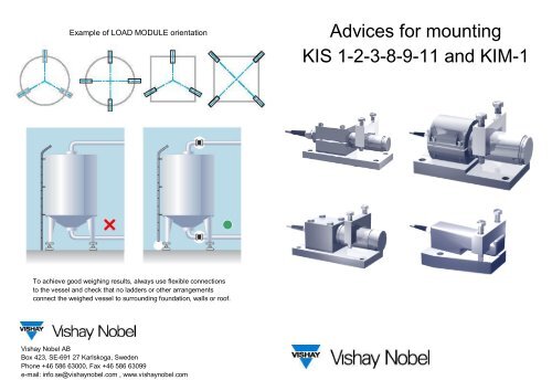
Example of LOAD MODULE orientation<strong>Advices</strong> <strong>for</strong> <strong>mounting</strong><strong>KIS</strong> 1-2-3-8-9-<strong>11</strong> <strong>and</strong> <strong>KIM</strong>-1To achieve good weighing results, always use flexible connectionsto the vessel <strong>and</strong> check that no ladders or other arrangementsconnect the weighed vessel to surrounding foundation, walls or roof.Vishay Nobel ABBox 423, SE-691 27 Karlskoga, SwedenPhone +46 586 63000, Fax +46 586 63099e-mail: info.se@vishaynobel.com , www.vishaynobel.com
1St<strong>and</strong>ard LOAD MODULE parts5Check that there isa lateral play betweenYOKE <strong>and</strong> LOAD CELL.LOAD CELLYOKEAssemble LOAD CELL, BRACKET,<strong>and</strong> YOKE to one LOAD MODULE.TILT GUARDOPTIONBRACKET OR PLATE2Level the LOAD MODULE <strong>and</strong> control that theload cell silicone protection is aligned with bracketfront (<strong>KIS</strong>-1-2-3-<strong>11</strong>).Adjust the measuring directionof the LOAD CELL (<strong>KIS</strong>-1-2-3-<strong>11</strong>)6Attach YOKES under the vessel supports<strong>and</strong> position the vessel on the LOADMODULES. Observe that the beddingshould be horizontal.The load module cables are recommendedto face the centre of the vessel.Mark the hole pattern <strong>and</strong> drill.Mount the bolts; re-positionthe LOAD MODULES<strong>and</strong> the vessel.3Recommended loadingpoint, check measure"x".Observe loading pointposition relativesurrounding mechanicalconstruction, that mustbe rigid enough.<strong>KIS</strong> 1-2-3-8-<strong>11</strong> <strong>and</strong> <strong>KIM</strong>-1<strong>KIS</strong> 97Check again the measure "x" betweenBRACKET <strong>and</strong> YOKE, <strong>and</strong> that thelateral play between YOKE <strong>and</strong> LOADCELL is preserved. See point 3 <strong>and</strong> 4.For installations with four LOADMODULES or more, the LOAD CELLoutput signals should be checked.Add shims between vessel support <strong>and</strong>YOKE to achieve similar signal levels.4<strong>KIS</strong> 1-2-3 -<strong>11</strong> <strong>KIS</strong>-8 <strong>KIM</strong>-1 <strong>KIS</strong>-9X (mm) X (mm) X (mm) X (mm)1 kN 35 1 kN 372 kN 35 2 kN 375 kN 35 5 kN 65 5 kN 2310 kN 55 10 kN 65 10 kN 2320 kN 55 20 kN 65 20 kN 2330 kN 5550 kN 65 50 kN 84 50 kN 33100 kN 65 100 kN 105 100 kN 42200 kN 65 200 kN 128 200 kN 60300 kN 658Important notices:IMPORTANT! WHEN DELIVERED THE MODULES ARE ONLYMOUNTED FOR TRANSPORTATION!Tighten all bolts <strong>and</strong> nuts according to engineering st<strong>and</strong>ards.Do not per<strong>for</strong>m any weldingwith the LOAD MODULE in place.