National Road B 31 â The Realization of a Privately Financed ...
National Road B 31 â The Realization of a Privately Financed ...
National Road B 31 â The Realization of a Privately Financed ...

Create successful ePaper yourself
Turn your PDF publications into a flip-book with our unique Google optimized e-Paper software.
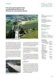
<strong>National</strong> <strong>Road</strong> B <strong>31</strong> – <strong>The</strong> <strong>Realization</strong> <strong>of</strong> a <strong>Privately</strong> <strong>Financed</strong> Project<br />
Ioannis RETZEPIS<br />
Managing Director<br />
Krebs und Kiefer GmbH<br />
Karlsruhe, GERMANY<br />
ret@ka.kuk.de<br />
Ioannis Retzepis, born 1961,<br />
received his PhD degree (Dr.-<br />
Ing.) from the Univ. <strong>of</strong><br />
Karlsruhe in 1995.<br />
He has been working for Krebs<br />
und Kiefer GmbH since 1993.<br />
He has been involved in many<br />
infrastructure projects as a<br />
designer or as a pro<strong>of</strong> engineer.<br />
Summary<br />
One <strong>of</strong> the first privately financed projects in Germany was the national road B <strong>31</strong> East between<br />
Freiburg and Kirchzarten. This infrastructure project not only helps realize an efficient traffic concept<br />
but permits a further development <strong>of</strong> the infrastructure <strong>of</strong> the city <strong>of</strong> Freiburg as well.<br />
As a direct result <strong>of</strong> the project, the overground East-West traffic is drastically reduced. This is<br />
achieved by directing the main traffic underground. Two double-cell tunnels (850 m and 1230 m) and<br />
two noise insulation galleries (275 m and 640 m) were planned. <strong>The</strong>se have been built in the inner city<br />
part <strong>of</strong> the project. <strong>The</strong> outer city part <strong>of</strong> the infrastructure project consists <strong>of</strong> five bridges including a<br />
number <strong>of</strong> noise insulation walls.<br />
<strong>The</strong> tunnels have been constructed using both the ‚cover and cut’ as well as the ‚cut and cover’ method.<br />
High security standards have been applied including a very sophisticated traffic control system.<br />
<strong>The</strong>se aspects, which are <strong>of</strong> importance in densely populated areas, are outlined in the paper.<br />
Keywords: privately financed project, infrastructure, concrete bridges, tunnels.<br />
1. History<br />
<strong>The</strong> national road B <strong>31</strong> is the most important East-West connection in the south-western part <strong>of</strong><br />
Germany. It links the motorway A 5 (Karlsruhe – Basel) with the A 81 (Stuttgart – Singen /<br />
Schaffhausen). <strong>The</strong> road B <strong>31</strong> East, which passes through the city <strong>of</strong> Freiburg and continues to<br />
Donaueschingen, plays a significant role in the Black Forest region from the touristic point <strong>of</strong> view as<br />
well.<br />
<strong>The</strong> idea <strong>of</strong> an efficient bypass through the city <strong>of</strong> Freiburg was born a long time ago. Since 1978<br />
extensive preliminary designs for traffic concepts have been carried out.<br />
<strong>The</strong> concept was to unite the conflicting goals <strong>of</strong> efficient traffic flow with an improved quality <strong>of</strong> life<br />
while at the same time respecting the environment. <strong>The</strong> finally developed traffic concept includes the<br />
following goals:<br />
• Lessening <strong>of</strong> traffic<br />
• Promotion <strong>of</strong> public transport<br />
• Promotion <strong>of</strong> bicycle paths<br />
• Traffic channelling into specific lanes<br />
• Management <strong>of</strong> parking spaces<br />
Due to the importance <strong>of</strong> the project, a very time-consuming process <strong>of</strong> authorization <strong>of</strong> the preliminary<br />
design followed. During this process the requests <strong>of</strong> several organizations as well as the concerns <strong>of</strong> the
esidents had to be taken into account. This process went on for 15 years and in the year 1993 the final<br />
preliminary design was authorized.<br />
<strong>The</strong> latest conception <strong>of</strong> the infrastructure project B <strong>31</strong> East not only realizes the stated goals but<br />
allows a further development <strong>of</strong> the infrastructure <strong>of</strong> the city <strong>of</strong> Freiburg.<br />
For such a big project with a total length <strong>of</strong> 7.8 km (inner city and outer city part), the financing<br />
scheme presented difficulties. Due to reduced government resources new ideas had to be adopted. <strong>The</strong><br />
new idea for such a big infrastructure project was to finance it privately. <strong>The</strong> government in Germany<br />
decided to use this financing mode for twelve traffic projects in total, one <strong>of</strong> them being the national<br />
road B <strong>31</strong>.<br />
2. Concept<br />
2.1 Financing Concept<br />
<strong>The</strong> federal investment program covering all infrastructure projects in Germany including bypasses <strong>of</strong><br />
cities was about 600 million € at this period <strong>of</strong> time. A further 200 million € for the so called ‘future<br />
investment program’ was also made available by the federal government. However, these reduced<br />
resources were not nearly enough so the new idea was to finance big infrastructure projects privately.<br />
Applying this financing concept, infrastructure projects worth 2,806 million € were carried out. With<br />
these projects new strong impulses were given to the building and construction industry as well as to<br />
the labour market.<br />
Without this new financing concept the B <strong>31</strong> project<br />
Parts Cost [€] would probably have not got further than the drawing<br />
board! <strong>The</strong> total cost <strong>of</strong> the project reached a sum <strong>of</strong><br />
1 Construction 150 million 300 million €. A small part <strong>of</strong> the project worth<br />
16 million € had to be excluded from this concept,<br />
2 Financial charges 95 million<br />
because it did not fit in with the conditions <strong>of</strong> the<br />
3 Acquisition <strong>of</strong> land 19 million financing concept. <strong>The</strong> main part <strong>of</strong> the cost <strong>of</strong><br />
284 million €, which fulfilled the given conditions, is<br />
4 Funding <strong>of</strong> the city <strong>of</strong> Freiburg 10 million<br />
listed in Table 1. <strong>The</strong> financial charges <strong>of</strong> the<br />
5 Advanced Payment <strong>of</strong> the state 10 million construction costs <strong>of</strong> 150 million € are 95 million €.<br />
Total 284 million<br />
<strong>The</strong>y have been calculated on the basis <strong>of</strong> a constant<br />
level <strong>of</strong> interest over the financing period <strong>of</strong> 15 years.<br />
This amount <strong>of</strong> 95 million € is divided into several<br />
Table 1 Cost structure <strong>of</strong> the project<br />
instalments, the first being 20 million €.<br />
2.2 Traffic Concept<br />
<strong>The</strong> direction <strong>of</strong> the main traffic underground effectively reduces the overground East-West traffic<br />
crossing through the city <strong>of</strong> Freiburg. This was the most important aim <strong>of</strong> the project. Many other<br />
benefits result directly from this. Improved traffic safety is one <strong>of</strong> them. This is achieved by the<br />
channelling <strong>of</strong> traffic and by reducing the crossing <strong>of</strong> the traffic lanes. <strong>The</strong> main East-West traffic<br />
consists <strong>of</strong> four lanes. In the outer part <strong>of</strong> the project the lanes were designed for a speed <strong>of</strong> 100 km/h.<br />
Because <strong>of</strong> the tunnel solution there is no crossing <strong>of</strong> these lanes in the inner part <strong>of</strong> the city. <strong>The</strong><br />
overground lanes are mainly reserved for resident traffic. <strong>The</strong> only main crossing is at the<br />
Lindenmattenstrasse, where the residential traffic crosses the North-South city traffic including a tram<br />
lane. Two foot- and bicycle-bridges complete this inner city concept.<br />
Apart from the very important aspect <strong>of</strong> road and traffic design many other aspects like the economical,<br />
agricultural, forestry, tourism and ecological ones had to be considered. <strong>The</strong> problems <strong>of</strong> sound<br />
emission and exhaust fumes were dealt with as well. 165 variations <strong>of</strong> a scheme needed to be discussed<br />
and evaluated in the decision-making process. <strong>The</strong> residents were also involved in this process.<br />
Parallel to the underground traffic, an overground train lane called ‘Hoellentalbahn’ serves as an
alternative to road traffic. <strong>The</strong> environmental aspects are also taken into account by promoting train,<br />
tram and bus in combination with the lessening <strong>of</strong> traffic. To emphasize this aspect, greenbelt areas <strong>of</strong><br />
park-like character were designated over the tunnel. Traffic areas which became obsolete were also<br />
integrated in the landscape design. <strong>The</strong> design <strong>of</strong> all the green areas was included in the structural<br />
design process and was discussed extensively with the residents.<br />
As a result, a very successful channelling <strong>of</strong> traffic is achieved and a dynamic infrastructure created,<br />
which increases not only the mobility <strong>of</strong> the residents but the quality <strong>of</strong> life as well.<br />
During the period <strong>of</strong> construction works no interruption <strong>of</strong> the traffic was allowed. <strong>The</strong> main problem<br />
was the crossing at the mouth <strong>of</strong> the first tunnel at the height <strong>of</strong> the Schwarzwaldstrasse. <strong>The</strong> lanes <strong>of</strong><br />
the main East-West traffic, the resident traffic as well as the tram traffic had to be designed and<br />
modified according to the building stages <strong>of</strong> the tunnel. To achieve this, one part <strong>of</strong> the traffic was<br />
allowed to run over the already built parts <strong>of</strong> the tunnel. Separate lanes for the site traffic needed to be<br />
designed as well. As mentioned before, crossings with other traffic lanes had to be avoided for safety<br />
reasons.<br />
<strong>The</strong> choice <strong>of</strong> efficient, economical as well as environmental-friendly methods <strong>of</strong> construction is a<br />
notable aspect <strong>of</strong> the project.<br />
2.3 Construction Concept<br />
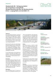
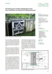
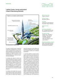
noise insulation<br />
gallery West<br />
Schuetzenallee<br />
tunnel<br />
Fig. 1 Aerial view <strong>of</strong> the structures in the inner city part<br />
Kappeller<br />
tunnel<br />
noise insulation<br />
gallery East<br />
To realize the above traffic concept, an underground construction for the inner city part with a total<br />
length <strong>of</strong> 3.5 km became necessary. It consists <strong>of</strong> two double-cell tunnels (850 m and 1230 m) and two<br />
noise insulation galleries (275 m and 640 m). <strong>The</strong> cost <strong>of</strong> these underground constructions makes up<br />
the major part <strong>of</strong> the total cost <strong>of</strong> the project. Due to the high level <strong>of</strong> underground water a waterpro<strong>of</strong>
concrete construction was chosen. Fig. 1 shows the aerial view <strong>of</strong> the structures in the inner city part; in<br />
this figure the main structures are marked. <strong>The</strong> tunnels were constructed using both the ‚cover and cut’<br />
as well as the ‚cut and cover’ method. <strong>The</strong> first method was applied to avoid disrupting the traffic. At<br />
the same time the noise nuisance was reduced which benefited the local residents.<br />
<strong>The</strong> outer part <strong>of</strong> the infrastructure project consists <strong>of</strong> five bridges - some being extremely skew - and a<br />
number <strong>of</strong> noise insulation walls.<br />
<strong>The</strong> huge amount <strong>of</strong> material, which was gained from the excavation, was used for the road works as<br />
well as for the production <strong>of</strong> concrete. <strong>The</strong> on-site produced concrete was sufficient for the entire<br />
construction, thus no additional concrete from other places needed to be ordered. In this way not only<br />
the economical point <strong>of</strong> view was considered but the environmental as well. This kept budgeting costs<br />
low and was ecologically pr<strong>of</strong>itable.<br />
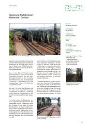
3. Constructions<br />
3.1 Tunnels<br />
<strong>The</strong> Schuetzenallee tunnel has a length <strong>of</strong> 850 m. <strong>The</strong> main part <strong>of</strong> the tunnel, the first 700 m, was<br />
constructed using the ‘cover and cut’ method. Before construction work could begin, the foundation <strong>of</strong><br />
many buildings running parallel to the tunnel had to be strengthened. This was achieved by applying jet<br />
grouting under their foundations. This proved essential because <strong>of</strong> the deep level <strong>of</strong> the building pit,<br />
which reached a depth <strong>of</strong> 13.0 m.<br />
<strong>The</strong> typical cross section <strong>of</strong> the tunnel blocks is a double-cell one with a middle wall which separates<br />
the two tubes. <strong>The</strong> tunnel deck ground cover varies from 0.25 m to 3.0 m.<br />
<strong>The</strong> following construction stages were planned for the ‘cover and cut’ part <strong>of</strong> the tunnel:<br />
• Stage 1: <strong>The</strong> outer bored piles with a diameter <strong>of</strong> 90 cm were set. <strong>The</strong> layout <strong>of</strong> the pile wall<br />
overlapped, with a scheme <strong>of</strong> a reinforced concrete pile following a non-reinforced concrete<br />
pile. Temporary steel columns were placed every 2.5 m for the middle wall (see Fig. 2).<br />
• Stage 2: <strong>The</strong> excavation was carried out till the bottom level <strong>of</strong> the deck. A sealing layer with<br />
transversal diaphragms every 40 m to 80 m was constructed.<br />
• Stage 3: <strong>The</strong> tunnel deck was built on a sub-base. Between the tunnel deck and the sub-base a<br />
gliding film was placed. <strong>The</strong> top <strong>of</strong> the deck was sealed and the area over the tunnel-deck could<br />
be used by the traffic.<br />
• Stage 4: Underground excavation. A system <strong>of</strong> ground water drainage for the rest <strong>of</strong> the ground<br />
water was installed. <strong>The</strong> piles <strong>of</strong> the outer walls as well as the columns <strong>of</strong> the middle wall were<br />
cleared <strong>of</strong> soil. A layer <strong>of</strong> shotcrete was sprayed over the outer pile walls.<br />
• Stage 5: A sub-base for the sole plate <strong>of</strong> the tunnel was built and a gliding film was placed on<br />
top <strong>of</strong> it. <strong>The</strong> tunnel blocks were built taking into account the underground water pressure. For<br />
this reason, each tunnel block was cast in one piece without any construction joints.<br />
• Stage 6: <strong>The</strong> road surfacing on the tunnel sole plate was built and finally the tunnel installation<br />
was carried out.<br />
In total, 2,500 pieces <strong>of</strong> concrete pile <strong>of</strong> a maximum length <strong>of</strong> 26.0 m were drilled. A total number <strong>of</strong><br />
8,000 drillings were necessary for the 14,000 m 2 sealing layer.<br />
<strong>The</strong> last 150 m <strong>of</strong> the Schuetzenallee tunnel as well as the whole Kappeller tunnel with a length <strong>of</strong><br />
1,230 m were built using the much easier method ‘cut and cover’. A Berlin-Type wall was used for the<br />
building pit, which reached a depth <strong>of</strong> up to 13.0 m. 900 m <strong>of</strong> the tunnel were constructed using<br />
movable scaffolding with a steel formwork. <strong>The</strong> casting <strong>of</strong> these tunnel blocks was done in one piece<br />
thus avoiding construction joints. <strong>The</strong> remaining 480 m <strong>of</strong> the tunnels were built in a conventional way<br />
using construction joints between the sole plate, the walls and the tunnel deck. A number <strong>of</strong> additional<br />
constructions were required before the tunnels could go into operation. This included underground<br />
control stations, emergency staircases, escape corridors with a maximum length <strong>of</strong> 300 m and utility
pipes <strong>of</strong> 2.0 m in diameter. At the mouth and tail-end <strong>of</strong> the tunnels, noise insulation aluminium<br />
elements were placed on the tunnel walls.<br />
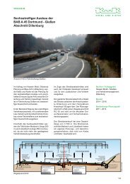
board pile wall<br />
10.5<br />
North tube<br />
0.0<br />
sealing layer<br />
+ 4.9<br />
21.0<br />
board pile<br />
10.5<br />
steel column<br />
South tube<br />
0.0 2.5<br />
sealing layer<br />
Fig. 2 Schuetzenallee-tunnel under construction<br />
At intervals in the tunnel, emergency parking spaces and connecting gates between the two traffic<br />
directions were planned. <strong>The</strong>se tunnel blocks required a special construction. <strong>The</strong> concrete decks have<br />
a form <strong>of</strong> a multiple T-beam cross-section and rest on the outer tunnel walls using bearings. Due to the<br />
double span <strong>of</strong> the system only prestressed concrete decks could be implemented. <strong>The</strong> deflection<br />
difference between the much stiffer double-cell tunnel blocks and the less stiff one-cell tunnel block<br />
was handled using waterpro<strong>of</strong> transition joints.<br />
In addition to the above mentioned constructions, sophisticated traffic control systems using computercontrolled<br />
cameras have been installed. So, for both tunnels, the Schuetzenallee and the Kappeller<br />
tunnel, high security standards have been applied. Finally, water reservoirs for the fire brigade were<br />
foreseen.<br />
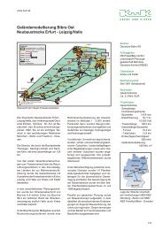
3.2 Noise Insulation Galleries<br />
Two noise insulation galleries with a length <strong>of</strong> 275 m and 640 m are placed between the two tunnels.<br />
<strong>The</strong>y break up the monotony <strong>of</strong> the tunnels by presenting interesting architectural elements. Only the<br />
north tunnel tube continues into the galleries with a concrete deck while the south tube is uncovered.<br />
Between these two tubes, the separating wall has been replaced by a row <strong>of</strong> diagonal slim columns (see<br />
Fig. 3). As a result, a transparency is achieved and day light floods into the covered tube. At the mouth<br />
and tail-end <strong>of</strong> the galleries noise insulation aluminium elements are fixed on the wall.<br />
board pile wall
Fig. 3 Start blocks <strong>of</strong> the noise insulation gallery<br />
3.3 Bridges<br />
<strong>The</strong> bridges are divided into two categories; inner city and outer city.<br />
<strong>The</strong> slim columns have a concrete joint at the<br />
top and are fixed in the sole plate at their base.<br />
<strong>The</strong>y consist <strong>of</strong> steel tubes filled with reinforced<br />
concrete. In this way the dimensions <strong>of</strong> the<br />
columns could be minimized.<br />
<strong>The</strong> two galleries are separated by an open<br />
space with a length <strong>of</strong> 505 m. Many types <strong>of</strong><br />
sustaining wall separate the traffic from the<br />
surroundings. A concrete wall between the two<br />
traffic directions marks the entrance to the<br />
galleries. <strong>The</strong> wall has the shape <strong>of</strong> a triangle<br />
with a wide opening (see Fig.3). <strong>The</strong> dimension<br />
<strong>of</strong> one side <strong>of</strong> the triangle was chosen taking<br />
into account the load case <strong>of</strong> a frontal vehicle<br />
impact. Two foot- and bicycle bridges cross<br />
above the galleries.<br />
3.3.1 Inner city Bridges<br />
<strong>The</strong> inner city traffic crossing over the B <strong>31</strong> is achieved either over the tunnel decks or by two foot- and<br />
bicycle bridges (Hammerschmied- and Bergaeckerbridge) at the height <strong>of</strong> the noise insulation galleries.<br />
<strong>The</strong> first bridge, the Hammerschmiedbridge, is a five-span bridge with a total length <strong>of</strong> 122.65 m. It<br />
crosses both the B <strong>31</strong> and the railway track <strong>of</strong> the ‚Hoellentalbahn’. <strong>The</strong> bridge was mainly cast in<br />
place. Only the middle part <strong>of</strong> it has been pre-fabricated in order to avoid interruption <strong>of</strong> the railway<br />
traffic during the construction period <strong>of</strong> the bridge.<br />
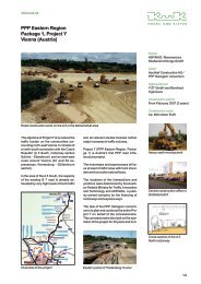
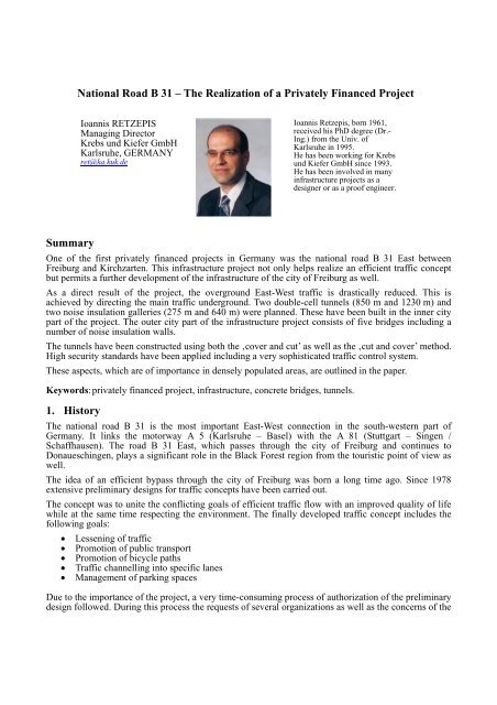
Fig. 4 Bridge <strong>of</strong> the road L 121 over B <strong>31</strong><br />
3.3.2 Outer city Bridges<br />
<strong>The</strong> B <strong>31</strong> East includes five outer city,<br />
concrete bridges. One <strong>of</strong> them is a<br />
bridge over a small river which was<br />
designed as a reinforced concrete<br />
frame. <strong>The</strong> width <strong>of</strong> the bridge is<br />
61.50 m. Another bridge is the one<br />
over the river Krummbach. It has a<br />
similar cross section and is 32.0 m in<br />
width. <strong>The</strong> bridge to the golf club<br />
over the B <strong>31</strong> is a two-span<br />
prestressed bridge with a T-beam<br />
cross-section. <strong>The</strong> superstructure is<br />
rigidly connected with the middle<br />
column <strong>of</strong> the bridge. <strong>The</strong> middle<br />
column had to be dimensioned taking<br />
into account the load case <strong>of</strong> vehicle<br />
impact as well.<br />
<strong>The</strong> most remarkable bridges <strong>of</strong> the<br />
B <strong>31</strong> East are the bridge <strong>of</strong> the road
L 121 over the B <strong>31</strong> and the bridge over the river Brugga. Although the span <strong>of</strong> these bridges is rather<br />
small, the detailing <strong>of</strong> the bridges had to be carefully designed, because these bridges affect the layout<br />
<strong>of</strong> the surrounding landscape. One main architectural prerequisite <strong>of</strong> the design was that the<br />
construction harmonizes with the surroundings. <strong>The</strong> bridge <strong>of</strong> the road L 121 over the B <strong>31</strong> is a twospan<br />
bridge with a total length <strong>of</strong> 44 m (Fig. 4). <strong>The</strong> 73° skew superstructure has a plate cross section<br />
and is longitudinally and transversally prestressed. <strong>The</strong> bridge deck has a varying width (minimum<br />
width 11.0 m) due to an additional traffic lane which begins on the bridge.<br />
<strong>The</strong> one-span bridge over the river Brugga has a length <strong>of</strong> 35.0 m. It consists <strong>of</strong> two parallel, 38° skew<br />
and 11.5 m wide superstructures. It has a double T-beam cross section. A prestressing in three directions<br />
was necessary. It consists <strong>of</strong> longitudinal tendons along the web <strong>of</strong> the T-beam, transversal tendons in<br />
the flange <strong>of</strong> the T-beam and straight tendons in the skew direction along the end cross beams. <strong>The</strong><br />
bridge was cast in place using classical scaffolding. <strong>The</strong> two abutments <strong>of</strong> the bridge rest on the same<br />
foundation but are separated by a joint.<br />
3.4 Sustaining Walls and further Constructions<br />
Sustaining walls <strong>of</strong> a length <strong>of</strong> 505 m are built between the two noise insulation galleries in the inner<br />
city part <strong>of</strong> the B <strong>31</strong> East. <strong>The</strong> architectural layout was also <strong>of</strong> importance due to the inner city location<br />
<strong>of</strong> these constructions. For this reason different types <strong>of</strong> walls are used: a sustaining wall consisting <strong>of</strong><br />
reinforced concrete pots with plants, a space frame wall which is also planted and a reinforced concrete<br />
wall. <strong>The</strong> combination <strong>of</strong> these construction systems avoids an abrupt transition from one system to the<br />
next. Fig. 5 shows the chosen systems.<br />
In the outer city part, between the Kappeller tunnel and the bridge <strong>of</strong> the street L 121 over the B <strong>31</strong>, the<br />
noise insulation structure consists mainly <strong>of</strong> noise insulation dams or noise insulation walls with acrylic<br />
glass or timber elements.<br />
A number <strong>of</strong> further constructions were needed for the functioning <strong>of</strong> the B <strong>31</strong> East. Rainwater pipes,<br />
sewage canals and drain pipes were built along the entire length <strong>of</strong> the road. Water reservoirs for the<br />
fire brigade were also planned in the project.<br />
Fig. 5 Inner city sustaining wall
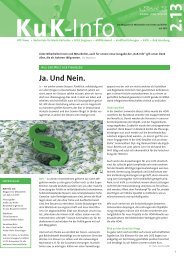
Fig. 6 Aerial view <strong>of</strong> the structures in the outer city part<br />
4. Conclusion<br />
One <strong>of</strong> the twelve privately financed projects in Germany was the infrastructure project <strong>of</strong> the national<br />
road B <strong>31</strong> East between Freiburg and Kirchzarten with a total length <strong>of</strong> 7.8 km. <strong>The</strong> primary concept<br />
was to combine the conflicting aspects <strong>of</strong> efficient traffic flow with those <strong>of</strong> an improved quality <strong>of</strong> life<br />
while respecting the environment. To achieve these goals a very time consuming decision-making<br />
process <strong>of</strong> 15 years followed. In this process the requests <strong>of</strong> several organizations as well as the<br />
concerns <strong>of</strong> the residents were regarded as far as possible.<br />
<strong>The</strong> main concept was to direct the East-West traffic, which runs through the inner city over a distance<br />
<strong>of</strong> 3.5 km, underground. This concept involved the building <strong>of</strong> two tunnels and two noise insulation<br />
galleries. As a result, an effective channeling <strong>of</strong> the traffic is achieved by avoiding the crossing <strong>of</strong> busy<br />
traffic lanes. <strong>The</strong> outer city part <strong>of</strong> the B <strong>31</strong> East (see Fig.6) includes five concrete bridges, which were<br />
designed to harmonize with the surroundings. A number <strong>of</strong> further constructions were needed to ensure<br />
high security standards. Independent safety inspectors have since awarded the tunnel a distinction in<br />
the category <strong>of</strong> ‘Best Safety’.<br />
<strong>The</strong> total cost <strong>of</strong> the main part <strong>of</strong> the project amounted to 284 million €. <strong>The</strong> financial charges <strong>of</strong> the<br />
construction costs <strong>of</strong> 150 million € are 95 million €, which have been calculated for a financing period<br />
<strong>of</strong> 15 years. <strong>The</strong> disadvantage <strong>of</strong> this long-term binding <strong>of</strong> state resources led the government to the<br />
decision not to apply this mode <strong>of</strong> financing for future projects. As a result, other modes which have<br />
been successfully applied abroad are currently in use for infrastructure projects in Germany.