RS-NAGU.2f - automation-safety
RS-NAGU.2f - automation-safety
RS-NAGU.2f - automation-safety
- No tags were found...

You also want an ePaper? Increase the reach of your titles
YUMPU automatically turns print PDFs into web optimized ePapers that Google loves.
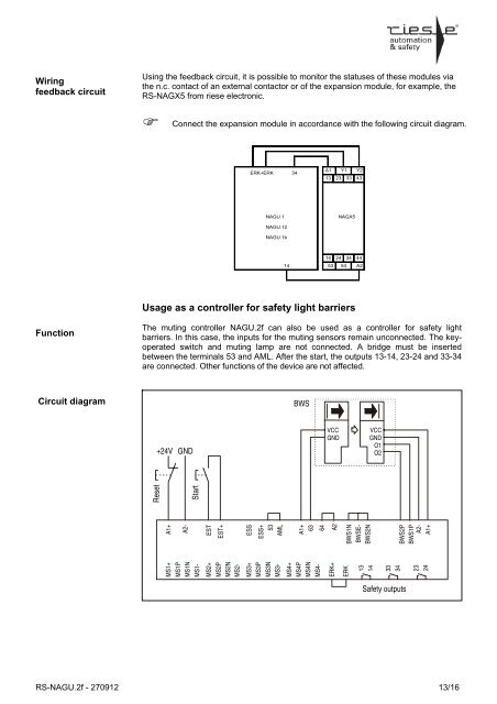
Wiringfeedback circuitUsing the feedback circuit, it is possible to monitor the statuses of these modules viathe n.c. contact of an external contactor or of the expansion module, for example, the<strong>RS</strong>-NAGX5 from riese electronic.Connect the expansion module in accordance with the following circuit diagram.ERK+ERK 34A1 Y1 Y213 23 33 43NAGU.1NAGX5NAGU.12NAGU.1b1414 24 34 4453 54 A2Usage as a controller for <strong>safety</strong> light barriersFunctionThe muting controller <strong>NAGU.2f</strong> can also be used as a controller for <strong>safety</strong> lightbarriers. In this case, the inputs for the muting sensors remain unconnected. The keyoperatedswitch and muting lamp are not connected. A bridge must be insertedbetween the terminals 53 and AML. After the start, the outputs 13-14, 23-24 and 33-34are connected. Other functions of the device are not affected.Circuit diagramBWS+24V GNDVCCGNDVCCGNDO1O2MS1+MS1PMS1NMS1-MS2+MS2PMS2NMS2-MS3+MS3PMS3NMS3-MS4+MS4PMS4NMS4-ERK+ERK131433342324A1+ESTEST+ESSESS+53AMLA1+6364A2BWS1NBWSE-BWS2NBWS2PBWS1PA2-A2-A1+ResetStartSafety outputs<strong>RS</strong>-<strong>NAGU.2f</strong> - 270912 13/16