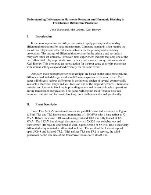
Understanding Differences in Harmonic Restraint and Harmonic ...
Understanding Differences in Harmonic Restraint and Harmonic ...
Understanding Differences in Harmonic Restraint and Harmonic ...
- No tags were found...

You also want an ePaper? Increase the reach of your titles
YUMPU automatically turns print PDFs into web optimized ePapers that Google loves.
Figure 3 Percentage Differential CharacteristicIn Figure 3, the height of horizontal l<strong>in</strong>e is I87m<strong>in</strong>. I87m<strong>in</strong> is the m<strong>in</strong>imum pickupsett<strong>in</strong>g to avoid differential misoperation due to CT <strong>and</strong> relay meter<strong>in</strong>g accuracy,transformer excitation current, etc. Two commercially available percentagedifferential characteristics are <strong>in</strong>cluded <strong>in</strong> Figure 3. The cont<strong>in</strong>uous curve is a littlemore mathematically <strong>in</strong>volved. The m<strong>in</strong>imum operat<strong>in</strong>g currents <strong>in</strong> three piecewisel<strong>in</strong>ear segments can be mathematically expressed asO87PWhen IR≤ , Iop= O87P(4)SLP1WhenO87P< IR≤ I , I = SLP1⋅ISLP1RS1 opR(5)WhenIWhen IRR> I I = SLP1⋅I + SLP2⋅(I − I ) (6.1)RS1 ,opRS1R RS1> I1, I = SLP2⋅I(6.2)RSopREquation (6.1) <strong>and</strong> (6.2) represents cont<strong>in</strong>uous slope characteristic <strong>and</strong> discont<strong>in</strong>uouscharacteristic respectively. Equation (4), (5), (6.1) <strong>and</strong> (6.2) can be expressed by a generalfunction asI = f ( I R)(7)op
IV.<strong>Harmonic</strong> Restra<strong>in</strong>t <strong>and</strong> <strong>Harmonic</strong> Block<strong>in</strong>g <strong>in</strong> Transformer DifferentialProtectionOther than different computation methods for restra<strong>in</strong>t current <strong>and</strong> the difference<strong>in</strong> operat<strong>in</strong>g curve when restra<strong>in</strong>t current is high, one major difference amongmicroprocessor relays from different manufacturers is how a relay restra<strong>in</strong>s fromoperation dur<strong>in</strong>g transformer energization.Transformers experience magnetiz<strong>in</strong>g <strong>in</strong>rush current dur<strong>in</strong>g energization <strong>and</strong> <strong>in</strong>rushcurrent appears to be a true differential current. The rich second harmonic component<strong>in</strong> <strong>in</strong>rush current is most commonly used to identify the condition of transformerenergization. Differential operation is supposed to be blocked dur<strong>in</strong>g normaltransformer energization.<strong>Harmonic</strong> restra<strong>in</strong>t was used <strong>in</strong> early electro-mechanical relays [1]. In the methoddescribed <strong>in</strong> [1], the restra<strong>in</strong>t current <strong>in</strong>cludes all the harmonics exclud<strong>in</strong>gfundamental <strong>and</strong> DC. Current flow<strong>in</strong>g <strong>in</strong> the restra<strong>in</strong>t coil tends to restra<strong>in</strong> theoperation from current flow<strong>in</strong>g <strong>in</strong> the operat<strong>in</strong>g coil, which conta<strong>in</strong>s fundamentalfrequency only. <strong>Harmonic</strong> block<strong>in</strong>g method has been <strong>in</strong>troduced <strong>in</strong> many modernmicroprocessor relays. With harmonic block<strong>in</strong>g, usually the second harmoniccomponent is used (fourth harmonic is used by some relay manufacturers). When theratio of the second harmonic component to the fundamental is greater than secondharmonic set po<strong>in</strong>t, <strong>in</strong>rush condition is announced <strong>and</strong> the differential operation isblocked.For harmonic block<strong>in</strong>g method, the differential operation criteria areAndI > f ( I R)(8)opIop2ndPCT 2< (9)I 100opAnd if fourth harmonic block<strong>in</strong>g is enabled,Iop4thPCT 4< (10)I 100opwhere PCT2 <strong>and</strong> PCT4 are the set po<strong>in</strong>ts for 2nd-harmonic block<strong>in</strong>g percentage <strong>and</strong>4th-harmonic block<strong>in</strong>g percentage respectively.<strong>Harmonic</strong> restra<strong>in</strong>t method may also be used <strong>in</strong> microprocessor relays. In one design,it uses only second <strong>and</strong> optional fourth harmonic component. The same sett<strong>in</strong>gs PCT2<strong>and</strong> PCT4 are used. The differential operation criteria is100 100> (11)PCT 2 PCT 4Iopf ( IR) + ⋅ Iop2nd+ ⋅Iop4th
IopSLP⎞ SLP⎜⎛ 1 100×0.3×2 100×7.5 × 21> ++ ⎟ ⋅IR= ( + 5.5)⋅I⎝ 100 15 10 ⎠ 100We see that if sett<strong>in</strong>g SLP 1= 25 , for this energization event, the differential operationwould need I > 5. 75 I , or the actual required operat<strong>in</strong>g slope from 25% to 575%.opRIf average restra<strong>in</strong>t (Equation(3)) is used, the maximum theoretical slope is 200%.With high harmonic components, the differential relay is not able to operate for a575% slope. However, if a transformer experiences a severe <strong>in</strong>ternal fault dur<strong>in</strong>genergization, the harmonic ratio will be limited (provided limited CT saturation) <strong>and</strong>the differential operation is not likely to be blocked. If a transformer experiences amoderate <strong>in</strong>ternal fault, it is possible that the differential operation be blocked untilthe energiz<strong>in</strong>g harmonic dies out or the moderate <strong>in</strong>ternal fault develops to a moresevere one.It would be <strong>in</strong>terest<strong>in</strong>g to see graphically how much the actual differential slopewould be raised for a specific harmonic restra<strong>in</strong>t sett<strong>in</strong>g. For simplicity, only the 2 ndharmonic restra<strong>in</strong>t is considered <strong>in</strong> this example. The sett<strong>in</strong>g of the 2 nd harmonic ratio(PCT2) is assumed to be 15%. SLP1 = 25%, SLP2 = 50%. The affect on the 2 nd slopepart is ignored for simplicity.RFigure 4. Dynamic shift<strong>in</strong>g of operat<strong>in</strong>g curve for harmonic restra<strong>in</strong>tIn Figure 4, actual slope of 100% is assumed, which applies to maximum restra<strong>in</strong>tcalculation method. The black operat<strong>in</strong>g curve is for the regular differential protectionwith harmonic block<strong>in</strong>g mechanism. The red operat<strong>in</strong>g curve is for differentialprotection with 7.5% of 2 nd harmonic ratio. S<strong>in</strong>ce we ignored the 4 th harmonic
100restra<strong>in</strong>t, the difference between the red curve black curve is ⋅ I op 2nd, , as wePCT 2can see from <strong>in</strong>equality (14). Per <strong>in</strong>equality (14), the actual differential slope is25 100*0.075+ = 75% if the actual 2 nd harmonic is 7.5%. The blue operat<strong>in</strong>g curve100 15is associated with 15% of 2 nd harmonic ratio. The slope is calculated to be 125% fromequation (14) if the actual 2 nd harmonic ratio is 15%.In Figure 4, only the 2 nd harmonic component is used <strong>in</strong> the harmonic restra<strong>in</strong>t. If the4 th harmonic restra<strong>in</strong>t is enabled with the 2 nd harmonic component, the slope of theoperat<strong>in</strong>g curve would be raised more significantly. In an energization event, theharmonic ratios fluctuate slightly. The actual operat<strong>in</strong>g curve changes dynamicallywith the actual calculated harmonic ratios.We have studied <strong>and</strong> illustrated the difference between harmonic restra<strong>in</strong>t <strong>and</strong>harmonic block<strong>in</strong>g <strong>in</strong> transformer differential protection. It is important to underst<strong>and</strong>the difference when we set transformer differential protection.V. Analysis of transformer differential eventsLet us review the event we <strong>in</strong>troduced section II. The recorded related SCADA eventsare listed <strong>in</strong> Table 1.Table 1: Recorded SCADA eventsDate <strong>and</strong> TimeOperation10/21/2008 7:06:58 AM BT1-2 Breaker Closed by Operator10/21/2008 7:07:42 AM TR1 34.5kV Breaker Opened byOperator10/21/2008 7:08:18 AM 115kV 5X148 Breaker Opened byOperator10/21/2008 7:08:50 AM 115kV 5X150 MOD Opened byOperator10/21/2008 7:09:35 AM 115kV 5X148 Breaker Closed byOperator10/21/2008 7:09:35 AM 115kV 5X148 Breaker Opened10/21/2008 7:09:35 AM TR2 34.5kV Breaker Opened10/21/2008 7:29:53 AM TR2 34.5kV Breaker Closed byOperator10/21/2008 9:02:03 AM 115kV 5X148 Breaker Closed byOperator10/21/2008 9:02:32 AM TR1 34.5kV Breaker Closed byOperator10/21/2008 9:02:12 AM BT1-2 Breaker Opened by Operator
Figure 5: Field recorded waveforms <strong>and</strong> derived current waveforms for differentialstudyFigure 6 illustrates that the differential relay would operate if proper restra<strong>in</strong>t(block<strong>in</strong>g) is not enabled.
Figure 6: (Iop, IR) <strong>in</strong>dicates differential trip without proper restra<strong>in</strong>tAs we discussed Section IV, the harmonic component plays an important role <strong>in</strong> thesecurity of differential operation dur<strong>in</strong>g energization. Tables 2 through 4 list theharmonic components for each phase of the operat<strong>in</strong>g current.Table 2: <strong>Harmonic</strong> components <strong>in</strong> phase A operat<strong>in</strong>g current
Table 3: <strong>Harmonic</strong> components <strong>in</strong> phase B operat<strong>in</strong>g currentTable 4: <strong>Harmonic</strong> components <strong>in</strong> phase C operat<strong>in</strong>g current
We see all phases have sufficient 2 nd harmonic ratio to have the differential operationblocked. However, if a relay is designed with 2 nd harmonic ratio calculated from eachcurrent <strong>in</strong>put <strong>in</strong>stead of the operat<strong>in</strong>g current, the 2 nd harmonic ratio is very low <strong>in</strong>this event. Tables 5 through 10 give the harmonic components for each phase oftransformer TR2 high side <strong>and</strong> low side currents separately.Table 5: <strong>Harmonic</strong> components <strong>in</strong> TR2 115kV A phase currentTable 6 <strong>Harmonic</strong> components <strong>in</strong> TR2 115kV B phase current
Table 7 <strong>Harmonic</strong> components <strong>in</strong> TR2 115kV C phase currentTable 8 <strong>Harmonic</strong> components <strong>in</strong> TR2 34.5kV A phase current
Table 9 <strong>Harmonic</strong> components <strong>in</strong> TR2 34.5kV B phase currentTable 10 <strong>Harmonic</strong> components <strong>in</strong> TR2 34.5kV C phase current
S<strong>in</strong>ce the secondary relay tripped on this event, we suspected <strong>and</strong> confirmed that therestra<strong>in</strong>t <strong>in</strong> the secondary relay is based on each current <strong>in</strong>put <strong>in</strong>stead of the operat<strong>in</strong>gcurrent. The root cause for this misoperation event from the secondary relay is theharmonic block<strong>in</strong>g is based on harmonic ratio calculated from the <strong>in</strong>dividual current<strong>in</strong>puts. In a sympathetic energiz<strong>in</strong>g event, the calculated harmonic ratio from one sideof transformer would be small due to exist<strong>in</strong>g large load currents.What we learned from this operation is to underst<strong>and</strong> as much as we can <strong>in</strong> the<strong>in</strong>ternal relay design <strong>and</strong> its operation pr<strong>in</strong>ciple. <strong>Underst<strong>and</strong><strong>in</strong>g</strong> the <strong>in</strong>ternal work<strong>in</strong>gsalso helps to expla<strong>in</strong> why differential operates or does not operate <strong>in</strong> event analysis.Here is another <strong>in</strong>terest<strong>in</strong>g <strong>and</strong> mysterious event happened to a distributiontransformer. A 115kV/13.8kV DABy (Dy1) transformer has a maximum rat<strong>in</strong>g of 28MVA. It has differential protection with both 2 nd <strong>and</strong> 4 th harmonic restra<strong>in</strong>t.Differential slope was set at 25%. Both 2 nd <strong>and</strong> 4 th harmonic ratios were set at 15%.CT ratios are CTR1 = 80 <strong>and</strong> CTR2 = 400. On July 27, 2011, the transformer wastripped mysteriously. Figure 7 illustrates the recorded current waveforms. CT 1 wasconnected to the high side <strong>and</strong> CT 2 was connected to the low side.Figure 7 Waveform from a mysterious trip of a Dy1 transformerFrom the recorded waveform, we see the load side currents were not disturbed beforethe trip. The high side currents were abnormal before the trip. S<strong>in</strong>ce the low (load)side currents were not disturbed, we suspected that it was a misoperation. After
pass<strong>in</strong>g a series of thorough tests on the CTs, transformers gas <strong>and</strong> wir<strong>in</strong>gconnections, the transformer was brought <strong>in</strong>to service without any problem. Load test<strong>in</strong>dicates operat<strong>in</strong>g current is zero. The root cause of the event rema<strong>in</strong>s unknown.What makes this event more <strong>in</strong>terest<strong>in</strong>g is that the same differential relay correctlyrestra<strong>in</strong>ed a feeder fault two days before this mysterious event. Figure 8 illustrates therecorded operat<strong>in</strong>g, restra<strong>in</strong>t <strong>and</strong> 2 nd harmonic current.Figure 8 Recorded operat<strong>in</strong>g, restra<strong>in</strong>t <strong>and</strong> 2 nd harmonic current.Provided the recorded waveforms, operat<strong>in</strong>g current, restra<strong>in</strong>t current, <strong>and</strong> 2 ndharmonic current are all correct, it is <strong>in</strong>terest<strong>in</strong>g to see that the differential relay wasdelayed at least 4 cycles.At t = 2.5 Cycles,IOP=0.33 pu, IRT=0.27 pu,Calculated Differential Slope=IOP/IRT = 0.33/0.27 = 122%.It looks like the differential trip should have tripped earlier per design. However, thedifferential trippedAt t = 4 Cycles,IOP=0.32 pu, IRT=0.26 pu,Calculated Differential Slope = IOP/IRT = 0.32/0.26 =123%.
The 1 st slope sett<strong>in</strong>g is 25% <strong>and</strong> the restra<strong>in</strong>t current did not reach the 2 nd sloperegion. S<strong>in</strong>ce harmonic restra<strong>in</strong>t was used, we need to check how much thedifferential slope would be raised dynamically.At t = 2.5 Cycles,2 nd harmonic I1F2 = 0.03 pu,2 nd harmonic ratio = I1F2/IOP1 = 0.03/0.33 = 9.1 %.The actual differential slope raised by 2 nd harmonic would be 9.1%/15%*122% =74%.The m<strong>in</strong>imum operat<strong>in</strong>g slope is 25% + 74% + Slope raised by 4 th harmonic= 99% + Slope raised by 4 th harmonicIf slope raised by 4 th harmonic is greater 23% to restra<strong>in</strong> (which requiresm<strong>in</strong>imum of 23%*15%/122%=2.8% 4 th harmonic ratio), then differentialoperation is restra<strong>in</strong>ed.At t = 4.0 Cycles,2 nd harmonic I1F2 = 0.02 pu,2 nd harmonic ratio = I1F2/IOP1 = 0.02/0.33 = 6.1 %.The actual differential slope raised by 2 nd harmonic would be 6.1%/15% *123%=50%.The m<strong>in</strong>imum operat<strong>in</strong>g slope is 25% + 50% + Slope raised by 4 th harmonic= 75% + Slope raised by 4 th harmonic.If slope raised by 4 th harmonic is less than 48% (which requires maximum 4 thharmonic ratio smaller than 48%*15%/123%=5.85%), the differential operationtrips.The actual 4 th harmonic dur<strong>in</strong>g the event is unknown s<strong>in</strong>ce downloaded waveformalready removed harmonics. The only reasonable assumption is that the 4 th harmonicratio was between 2.8% <strong>and</strong> 5.85% dur<strong>in</strong>g this event.Although the root cause of this event rema<strong>in</strong>s unknown, we see that how harmoniccomponents can raise the operat<strong>in</strong>g slope significantly for differential relay withharmonic restra<strong>in</strong>t implemented. This event tells us that it is very important to avoidCT saturation dur<strong>in</strong>g <strong>in</strong>ternal fault if harmonic restra<strong>in</strong>t is used.VI.ConclusionAn <strong>in</strong>terest<strong>in</strong>g field sympathetic <strong>in</strong>rush event, which prompted the <strong>in</strong>itial study of thispaper, is presented <strong>in</strong> the paper. When a de-energized transformer was connected <strong>in</strong>parallel to a fully loaded transformer, the fully loaded transformer was tripped out byits differential relay. S<strong>in</strong>ce each of the two parallel transformers has its owndifferential protection, the unwanted trip is of particular <strong>in</strong>terest for this sympathetic<strong>in</strong>rush event. A thorough analysis from the event record expla<strong>in</strong>s the differentresponses from the two relays. The primary relay uses harmonic restra<strong>in</strong>t method <strong>and</strong>the secondary relay uses the harmonic block<strong>in</strong>g method. Another important difference
is that harmonic calculation is based on the operat<strong>in</strong>g current <strong>in</strong> the primary relay butharmonic calculation is based on each current <strong>in</strong>put only. It is concluded thatharmonic restra<strong>in</strong>t provides better security <strong>and</strong> harmonic block<strong>in</strong>g provides betterdependability for transformer protection. It is also concluded that harmoniccalculation based on operat<strong>in</strong>g current offers better security for transformerenergization dur<strong>in</strong>g transformer energization.This study may help protection eng<strong>in</strong>eers to have a better underst<strong>and</strong><strong>in</strong>g the <strong>in</strong>ternalwork<strong>in</strong>gs of harmonic restra<strong>in</strong>t. In sett<strong>in</strong>g differential relays, to achieve closerperformance, it may be helpful to set the harmonic ratio slightly higher for differentialrelays with harmonic restra<strong>in</strong>t <strong>and</strong> set harmonic ratio slightly lower for differentialrelays with block<strong>in</strong>g.VII.References[1] General Electric GEH-1816, BDD15B/BDD16B Transformer Differential Relaywith Percentage <strong>and</strong> <strong>Harmonic</strong> Restra<strong>in</strong>t[2] Behrendt K., Fischer N., Labuschagne C, ”Considerations for Us<strong>in</strong>g <strong>Harmonic</strong>Block<strong>in</strong>g <strong>and</strong> <strong>Harmonic</strong> Restra<strong>in</strong>t Techniques on Transformer Differential Relays”,2006 Western Protective Relay ConferenceVIII.AcknowledgementThe authors would like to thank Mark Gutzmann, Joshua Erdman <strong>and</strong> John Berz<strong>in</strong>s atXcel Energy for their valuable discussions dur<strong>in</strong>g the development of this paper. Theauthor would also like to thank several relay manufacturers for their coord<strong>in</strong>ation toprovide <strong>in</strong>formation on their <strong>in</strong>ternal designs.IX.BiographyJohn Wang received his B.S. <strong>and</strong> M.S. <strong>in</strong> electrical eng<strong>in</strong>eer<strong>in</strong>g from ZhejiangUniversity <strong>in</strong> 1985 <strong>and</strong> 1988 respectively. He earned a second M.S. <strong>in</strong> electricaleng<strong>in</strong>eer<strong>in</strong>g from University of Missouri-Rolla <strong>in</strong> 1997. He was an assistant professor<strong>in</strong> Zhejiang University from 1988 to 1994. He jo<strong>in</strong>ed Basler Electric <strong>in</strong> 1998, was apr<strong>in</strong>cipal eng<strong>in</strong>eer <strong>and</strong> had almost 12 years experience design<strong>in</strong>g protective relays <strong>and</strong>support<strong>in</strong>g customer relay applications. He jo<strong>in</strong>ed Xcel Energy <strong>in</strong> September 2010 asa Pr<strong>in</strong>cipal Eng<strong>in</strong>eer <strong>in</strong> System Protection Eng<strong>in</strong>eer<strong>in</strong>g. He is a registered professionaleng<strong>in</strong>eer, a senior member of IEEE, a member of the IEEE St<strong>and</strong>ard Association,IEEE Power Eng<strong>in</strong>eer<strong>in</strong>g Society, <strong>and</strong> IEEE Power System Relay<strong>in</strong>g.John Grimm received his B. S. <strong>in</strong> Electrical <strong>and</strong> Electronis Eng<strong>in</strong>eer<strong>in</strong>g from NorthDakota State University <strong>in</strong> 1986. He has over 20 years of protective relay<strong>in</strong>gexperience. He is presently the Supervisor of the System Protection Eng<strong>in</strong>neer<strong>in</strong>g
(NSP) at Xcel Energy. He is a registered professional eng<strong>in</strong>eer <strong>in</strong> the State ofM<strong>in</strong>nesota, <strong>and</strong> a member of IEEE.