- Page 4 and 5: 1: Scope and application• Scope:
- Page 6: 1: Scope and application• Inspect
- Page 9: 4: Structural documents• Drawings
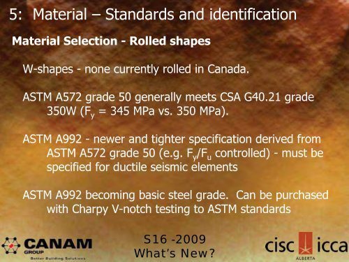
- Page 13 and 14: 5: Material - Standards and identif
- Page 15 and 16: 6: Design requirements• For speci
- Page 17 and 18: 13.5 Bending - Laterally supported
- Page 19 and 20: 4Mmax222 2 2Mmax 4Ma 7Mb 4Mc2.5M ma
- Page 21 and 22: 13.6 (e) Flexure of monosymmetric s
- Page 23 and 24: 13.6 (e) Flexure of monosymmetric s
- Page 25 and 26: 13.4 ShearShear resistance:Clause 1
- Page 27 and 28: 13.2 Tension & 13.11 Block ShearA c
- Page 29 and 30: 12 Gross and net areasDefined in Cl
- Page 31 and 32: 13.11 Block shearBlock shearNew exp
- Page 33 and 34: 13.11 Block shearBlock shearWhat to
- Page 35 and 36: 13.3 Axial compressionModified dete
- Page 37 and 38: 13.3.2 Flexural, torsional, or flex
- Page 39 and 40: 13.3.3.1 GeneralGeneral - single an
- Page 41 and 42: 13.3.3.2 Individual members and pla
- Page 43 and 44: 13.3.3.3 Box and space trussesModif
- Page 45 and 46: 13.3.4 Segmented members in compres
- Page 47 and 48: 13.3.5 Members in compression subje
- Page 49 and 50: 25 Column bases and anchor rodsBear
- Page 51 and 52: 16 Open-web steel joists16.5.1 Load
- Page 53 and 54: 16 Open-web steel joists16.5.14 Cam
- Page 55 and 56: 16 Open-web steel joists16.12.2 Ere
- Page 57 and 58: 17 Composite beams, trusses, and jo
- Page 59 and 60: 17 Composite beams, trusses, and jo
- Page 61 and 62:
17 Composite beams, trusses, and jo
- Page 63 and 64:
18 Composite columnsNew values of
- Page 65 and 66:
18 Composite columns18.3 Partially
- Page 67 and 68:
20 Plate wallsAngle of inclination:
- Page 69 and 70:
20 Plate walls20.5 Limits on column
- Page 71 and 72:
20 Plate wallsSeismic requirementsT
- Page 73 and 74:
20 Plate wallsType D plate walls1)
- Page 75 and 76:
20 Plate walls27.9.2.4 Infill plate
- Page 77 and 78:
20 Plate walls27.9.4 ColumnsClass 1
- Page 79 and 80:
20 Plate walls27.10 Type LD (limite
- Page 81 and 82:
13.12 Bolts and local connection re
- Page 83 and 84:
13.13 Welds13.13.2.2 Fillet weldsTw
- Page 85 and 86:
21.3 Restrained membersThe shear fo
- Page 87 and 88:
21.10 Fastener and welds in combina
- Page 89 and 90:
Joint surface conditionsClauses 24.
- Page 91 and 92:
Annex L Design to prevent brittle f
- Page 93 and 94:
Annex L Design to prevent brittle f
- Page 95 and 96:
Annex L Design to prevent brittle f
- Page 97 and 98:
Annex K Structural design for fire
- Page 99 and 100:
Annex K Structural design for fire
- Page 101 and 102:
Annex K Structural design for fire
- Page 103 and 104:
Annex K Structural design for fire
- Page 105 and 106:
Annex K Structural design for fire
- Page 107 and 108:
Annex K Structural design for fire
- Page 109 and 110:
Annex K Structural design for fire
- Page 111 and 112:
Annex K Structural design for fire
- Page 113 and 114:
Annex K Structural design for fire
- Page 115 and 116:
Annex K Structural design for fire
- Page 117 and 118:
Annex K Structural design for fire
- Page 119 and 120:
Clause 27 Seismic designStructures
- Page 121 and 122:
Clause 27 Seismic design27.1.4 Memb
- Page 123 and 124:
Clause 27 Seismic design27.1.8 Stab
- Page 125 and 126:
Clause 27 Seismic design27.2.8 Prot
- Page 127 and 128:
Clause 27 Seismic design27.5 Type M
- Page 129 and 130:
Clause 27 Seismic design27.6.6 Colu
- Page 131 and 132:
Clause 27 Seismic design27.7.6 Link
- Page 133 and 134:
Clause 27 Seismic design27.8 Type D
- Page 135 and 136:
Clause 27 Seismic design27.8.3 (BRB
- Page 137 and 138:
Clause 27 Seismic design27.8.6 (BRB
- Page 139 and 140:
Clause 27 Seismic design27.11 Conve
- Page 141 and 142:
Clause 27 Seismic design27.11 Conve
- Page 143:
S16 -2009What’s New?