do-al installation instructions - Highway Equipment Company
do-al installation instructions - Highway Equipment Company
do-al installation instructions - Highway Equipment Company
- No tags were found...

Create successful ePaper yourself
Turn your PDF publications into a flip-book with our unique Google optimized e-Paper software.
DO-AL INSTALLATION INSTRUCTIONSRevision BEFFECTIVE 06/20111330 76TH AVE SWCEDAR RAPIDS, IA 52404-7052PHONE (319) 363-8281 | FAX (319) 286-3350www.highwayequipment.comCopyright 2009 <strong>Highway</strong> <strong>Equipment</strong> <strong>Company</strong>, Inc.
table of ContentsHI-WAYTable header of ContentsTruck Preparation.......................................................................................................................................... 3Transmission PTO - Pump Selection.................................................................................................. 4PTO - Pump Match Graph................................................................................................................. 4Crankshaft PTO - Pump Selection..................................................................................................... 4Hydraulic Pump Inst<strong>al</strong>lation.......................................................................................................................... 5Transmission PTO Drive.................................................................................................................... 5Crankshaft PTO Drive........................................................................................................................ 5Hydraulic Pump Drive Shaft Inst<strong>al</strong>lation........................................................................................................ 6Cab Control V<strong>al</strong>ve Inst<strong>al</strong>lation....................................................................................................................... 6Mounting of Spreader Body.......................................................................................................................... 6Truck Frame Length.......................................................................................................................... 6Wood Filler Strips.............................................................................................................................. 6Positioning Body............................................................................................................................... 7Inst<strong>al</strong>lation Front Mounting Angles.................................................................................................. 7Inst<strong>al</strong>ling Center Mounting Angles.................................................................................................... 7Inst<strong>al</strong>ling Rear Mounting Angles....................................................................................................... 8Securing Spreader Body to Frame.................................................................................................... 8Spinner Assembly Inst<strong>al</strong>lation....................................................................................................................... 8Do-Al Elevator Attachment........................................................................................................................... 9Cab Shield Inst<strong>al</strong>lation................................................................................................................................. 1 4Hydraulic Hose Inst<strong>al</strong>lation......................................................................................................................... 1 5Hydraulic Hose Maintenance...................................................................................................................... 1 6Hose Inst<strong>al</strong>lation Guide............................................................................................................................... 1 7Electric<strong>al</strong> Connections................................................................................................................................. 1 8Filling Hydraulic System.............................................................................................................................. 1 8Checking Inst<strong>al</strong>lation................................................................................................................................... 1 8<strong>do</strong>-AlPage Rev. A2
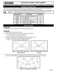
Hi-WayInst<strong>al</strong>lation InstructionsDO-AlTRUCK PREPARATIONIn mounting the Do-Al spreader on a truck, the following major questions are to be considered:1. Is the CA (Cab to Axle) dimension of the truck correct for the length of the spreader?To answer this question, see the “Dimension and Capacities” Chart. This will assist in matching spreader totruck.2. Is the truck’s GAWR (Gross Axle Weight Rating) and the GVWR (Gross Vehicle Weight Rating) adequate to carrythe fully loaded spreader?To answer this question, refer to your Hi-Way de<strong>al</strong>er. He knows where to find the GAWR and GVWR for mosttrucks, and how to c<strong>al</strong>culate the weight distribution on each axle and tot<strong>al</strong> loaded vehicle weight.3. How will the hydraulic pump be driven?The answer to this question will depend upon the availability of means to drive a pump that exists on theparticular truck chosen for the mounting. Your de<strong>al</strong>er should be able to help here <strong>al</strong>so. The following explainsthe procedure for determining the correct PTO-Pump match if the pump is to be ordered from <strong>Highway</strong><strong>Equipment</strong> <strong>Company</strong>.I nsta llat i n sta ion llat InstructionsTransmission PTO-Pump SelectionDetermine the maximum engine speed of the truck to be used. On the PTO-Pump Match Graph locate the maximumspeed on the engine RPM sc<strong>al</strong>e. Draw a line up from this point until it reaches the 2000 RPM horizont<strong>al</strong> line of thePTO-Pump RPM sc<strong>al</strong>e. The maximum PTO percentage to be used will be at the point where the maximum engineRPM line crosses the 2000 RPM line. Determine a PTO percentage at or below the maximum PTO percentage whichfits your particular transmission application.Draw a line over from the point where the chosen PTO percentage line crosses the maximum engine RPM line. Thecorrect pump to be used will be one that intersects this line in the GPM range required. For the Do-Al hydraulicsystem, this range is 35 to 40 GPM.For example, if the maximum engine RPM of the truck to be used is 3000 RPM, a vertic<strong>al</strong> line from this point wouldintersect the 2000 PTO-Pump RPM sc<strong>al</strong>e at the 67% PTO hash mark. If the nearest available PTO at or below 67% forthe transmission is 54%, drawing in the line for the 54% PTO and drawing a line over from where this line intersectsthe maximum engine RPM line crosses the 22397 pump curve in the desired GPM range. This would be the correctpump to use for the particular engine speed-PTO percentage used in this example.Please note that unless otherwise specified, the Do-Al spreader will be shipped with Pump Number 22397 when thestandard pump option is ordered.If the PTO-Pump matching will not fit into the speed and delivery volumes required for the spreader, refer to yourHi-Way de<strong>al</strong>er.3Page Rev. APage Rev. A
HI-WAYInst<strong>al</strong>lation Instructions ContinuedDo-ALPTO-Pump Match GraphI nst<strong>al</strong>lation InstructionsCrankshaft PTO-Pump SelectionFigure 1 - PTO-Pump Match GraphIn this case, if this option is ordered, the PTO percentage is 54%. Determine the maximum engine RPM of the truckto be used and follow the procedure above for drawing the engine speed line.Draw a line over from where the engine speed line and the 54% PTO line intersect to determine the correct pumpto use. Please note that the correct pump to order, however, would be the direct mount version of the pumps liste<strong>do</strong>n the graph. See the table below for crossover numbers.Pump Part No.Driveline/Direct Mount22395/3016822396/3123222397/3684722398/31233Pump GPM3537354035403540Pump RPM19002000165019001500170013501550Page Rev. A4
Hi-WayInst<strong>al</strong>lation Instructions ContinuedDO-AlIMPORTANT!Do not select a PTO % and an engine RPM resulting in more than 2000 PTO RPM. Driving thepumps (referenced above) at speeds greater than 2000 RPM will result in premature failureof the pump and other hydraulic components.Please note that unless otherwise specified, the Do-Al spreader will be shipped with Pump Number 36847 when theCrankshaft PTO-Pump option is ordered.If PTO-Pump matching will not fit into the speed and delivery volumes required for the spreader, refer to yourHi-Way de<strong>al</strong>er.Recommended sequence of inst<strong>al</strong>lation is as follows:1. Mounting of pump and pump drive.2. Inst<strong>al</strong>lation of cab controls.3. Mounting of spreader.4. Inst<strong>al</strong>lation of hydraulic hose and electric<strong>al</strong> wiring.5. Filling hydraulic tank and lubrication.6. Checking for leaks and functioning.HYDRAULIC PUMP INSTALLATIONI nsta llat ion InstructionsTransmission PTO DriveA mounting bracket for the hydraulic pump is shipped with the spreader. It may be necessary to modify this bracketto fit your truck, since many variable factors, such as PTO make and model, muffler position, transmission make andmodel, etc., <strong>al</strong>l affect the mounting position. DO NOT WELD THE BRACKET TO THE TRUCK FRAME, to <strong>do</strong> so may voidthe truck manufacturer’s warranty.Position the mounting bracket so that the pump drive shaft will be as straight as possible. In no case may the angleat any univers<strong>al</strong> joint exceed 15°. The pump shaft and the PTO shaft should be par<strong>al</strong>lel. (Figure 2)Crankshaft PTO DriveAs a crankshaft PTO drive norm<strong>al</strong>ly required repositioning of both truck radiator and front bumper, it is recommendedthat the truck be procured by specifying that it be adapted for front crankshaft PTO inst<strong>al</strong>lation. A crankshaftadapter to fit either a “Spicer” type or “Mechanics” type univers<strong>al</strong> joint companion flange should be specified.If the vehicle is not <strong>al</strong>ready adapted for front crankshaft PTO inst<strong>al</strong>lation, the following steps must be followed:A crankshaft adapter described above must be supplied. The radiator must be raised or modified to <strong>al</strong>low the PTOdriveline to pass beneath it. The radiator fan must <strong>al</strong>so clear <strong>al</strong>l parts of the PTO driveline. The fan shroud, if any,must be modified to suit the new radiator position. It is recommended that your loc<strong>al</strong> truck de<strong>al</strong>er or radiatorspeci<strong>al</strong>ist be consulted for guidance.The front bumper must be moved forward far enough to clear <strong>al</strong>l PTO components. A mounting channel is tobe fabricated loc<strong>al</strong>ly to provide a mounting surface on which the PTO must be positioned par<strong>al</strong>lel to the enginecrankshaft centerline. The univers<strong>al</strong> joint timing is to be as shown in Figure 1.Pump drive control cable is to be located at a convenient point in the truck cab, usu<strong>al</strong>ly on instrument panel, and runto the pump drive engaging lever on the PTO. Avoid sharp bends in the cable, moving parts and hot manifold andexhaust pipe. Secure cable sheath near each end and at frequent intermediate points with cable clips.5Page Rev. A
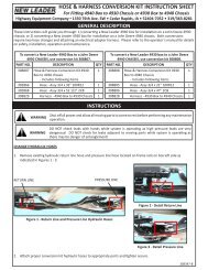
HI-WAYInst<strong>al</strong>lation Instructions ContinuedDo-ALHYDRAULIC PUMP DRIVE SHAFT INSTALLATIONThe pump drive shaft included may be too long for some inst<strong>al</strong>lations. It may be cut and redrilled as necessary.When redrilling the shaft, be sure that univers<strong>al</strong> joints are properly “timed”.Inst<strong>al</strong>l the slip joint at the end of the pump drive shaft. Failure to inst<strong>al</strong>l the slip joint will result in bearing failure inpump, PTO, or both.Par<strong>al</strong>lel ShaftsNot To Exceed15 DegreesPar<strong>al</strong>lel ForksI nst<strong>al</strong>lation InstructionsCAB CONTROL VALVE INSTALLATIONFigure 2 - Timing of Univers<strong>al</strong> JointsWhen selecting a location for the cab control v<strong>al</strong>ve there are a number of items to consider:1. Select a suitable location for the operator to adjust the control and to turn it On and Off.2. Check for clearance with the seat in <strong>al</strong>l positions.3. Check the transmission gearshift in <strong>al</strong>l gears for clearance with the v<strong>al</strong>ve and with the v<strong>al</strong>ve lever in the On andOff positions.4. If there are any other controls, such as parking brake, plow and wing controls, check for clearance.5. Under the cab, check for interference with transmission, etc.CAUTIONMOUNTING OF SPREADER BODYTruck Frame LengthAll holes in truck cab w<strong>al</strong>ls, floor and fire w<strong>al</strong>l for control wires, hoses and cables are to begrommeted, plugged and se<strong>al</strong>ed to prevent entrance of engine fumes, dust, dirt, water andnoise.In most cases, the truck frame must be shortened. The length from the rear of the cab to the end of the frameshould be approximately as shown on the “Dimension and Capacities” Chart under C.Wood Filler StripsHardwood filler strips (not supplied with spreader) one inch (1”) (2.54 cm) by three inches (3”) (7.62 cm) must beinst<strong>al</strong>led the length of the frame behind the truck cab. Cut the filler strip to length and place on top of the truckframe rails. With a heavy hammer, strike directly above each rivet head to mark the position of the rivet. Removethe filler strips and counterbore for the rivet heads. Replace the filler strips and hold them in place by bendinganchor clips as shown in Figure 2. If the truck frame has fish plates on the top flange, it will be necessary to provide aPage Rev. A6
Hi-WayInst<strong>al</strong>lation Instructions ContinuedDO-Allevel top surface by adding steel shim bars or strips of the same thickness as the fish plates and as wide as the framechannel top flange. These shim bars or strips must be drilled out to clear any rivet or bolt heads and may be tackwelded to fishplates. DO NOT WELD these bars or strips to the truck frame—to <strong>do</strong> so may void truck manufacturer’swarranty. Place the wood filler strips on top of them and secure both steel shims and wood filler strips by means ofbending the anchor clips around them and the frame top flanges as shown in Figure 3. Each steel shim bar or stripand each separate wood filler strip must be secured by at least two anchor clips. Full length filler strips should eachhave at least three anchor clips. Secure each anchor clip by driving 1/4” sheet met<strong>al</strong> screw through clip into woodfiller strip as shown in Figure 3.Hardwood Filler StripAnchor ClipFish Plate1/4” SheetMet<strong>al</strong> Screw1/4” SheetMet<strong>al</strong> ScrewTruck FrameHardwoodFiller StripAnchor ClipShim BarTruckFrame RailShim Bar - Tack Weld to Fish Plate(Not Truck Frame)Truck FrameRailI nsta llat ion InstructionsFigure 3 – Wood Filler Strips & Anchor ClipsIMPORTANT!DO NOT PUT HOLES INTO TOP OR BOTTOM FLANGES—to <strong>do</strong> so may void truck manufacturer’swarranty. When drilling holes in frame member, drill only through vertic<strong>al</strong> web portions.Positioning BodyPlace the spreader body on the truck frame. Position body centr<strong>al</strong>ly with respect to the truck frame rails andapproximately six inches (6”) (15.24 cm) to the rear of the cab. Check the position of the spreader at the rear toinsure that the rear mounting plates can be properly positioned on truck frame and centered on rear cross sill.Inst<strong>al</strong>ling Front Mounting PlatesNOTE: When inst<strong>al</strong>ling front, center, and rear mounting plates, a minimum of four inches (4”) (10.16 cm) of thevertic<strong>al</strong> sides of each plate must be in contact with the spreader sills. (Figure 4)Position the two front mounting plates with the slotted surfaces against the side of the truck frame, approximately25” (63.5 cm) from the front. Mark the location of the slot on the truck frame. Drill two (2) 9/16” (1.43 cm)diameter holes through the truck frame, 1 1/4” (3.18 cm) from the bottom of the slots. (Figure 4)7Page Rev. A
HI-WAYInst<strong>al</strong>lation Instructions ContinuedDo-ALCAUTIONWhen drilling holes, make sure that the drill will not puncture the gas tank or harm any otherobstruction!Inst<strong>al</strong>ling Center Mounting PlatesPosition the center mounting plates at a convenient location near the center of the body with the slotted surfaceagainst the truck frame and mark the location of the slots on the truck frame. Drill two (2) 9/16” (1.43 cm) diameterholes through the truck frame, approximately 3/4” (1.91 cm) from the bottom of the slot. (Figure 4)NOTE: The position of the center mounting plates will vary from truck to truck due to obstructions, such as springshackles, etc.Inst<strong>al</strong>ling Rear Mounting PlatesI nst<strong>al</strong>lation InstructionsPosition the rear mounting plates with the slotted surface against the sides of the truck frame. Mark the locationof the slots on the truck frame. Drill two (2) 9/16” (1.43 cm) diameter holes through the truck frame at the bottomend of the slots. (Figure 3)Securing Spreader Body to FrameIMPORTANT!IMPORTANT!DO NOT WELD TO VEHICLE FRAME! Such welding can lead to fatigue cracking and must beavoided. DO NOT drill through frame flanges.If at anytime an arc welder is used on the vehicle or anything connected to the vehicle, besure to connect the welders ground directly to one of the two items being welded.Inst<strong>al</strong>l the mounting plates, positioning them as described, and tighten the mounting bolts according to the torquechart. Weld the mounting angles to the spreader sills by welding them on the front, top and rear sides.SPINNER ASSEMBLY INSTALLATIONSlide the chute assembly in above the sills and bolt in with 3/8” stainless steel hardware.Inst<strong>al</strong>l the righthand and lefthand hinge. Using any suitable hoist or jack, lift the spinner assembly into position andinst<strong>al</strong>l the four pins. Connect the two hose assemblies with the quick disconnect fittings. (Figure 4 and SpinnerParts List in operator’s manu<strong>al</strong>.)Page Rev. A8
HI-WAYInst<strong>al</strong>lation Instructions ContinuedDo-ALI nst<strong>al</strong>lation InstructionsFigure 6 – Panel Bracket LocationFigure 7 – Control V<strong>al</strong>ve Inst<strong>al</strong>lation3. Position the panel bracket, #37962, on the righthand side sheet as shown in Figure 6. Using the bracket as atemplate, drill four (4) 5/16” (.8 cm) dia. holes in the RH side sheet. Mount the panel with four (4) 1/4-20NC x1” cap screws and nuts provided. Mount the #32485 elevator speed control v<strong>al</strong>ve as shown in Figure 7 with two(2) 1/4-20NC x 2 1/2” cap screws and nuts provided.Figure 8 – Template 37984 Location4. Remove and cut out the drilltemplates from drawings#37983 and #37984.5. Position template #37984as shown in Figure 8.Center punch places whereshown and drill the ten (10)numbered 9/16” (1.43 cm)diameter holes into theDo-Al endgate.6. With a suitable hoist, raise the winch assembly into position and fasten to endgate with ten (10) 1/2” cap screws,nuts and lock washers. Tighten <strong>al</strong>l ten capscrews per Torque Chart recommendations in operator’s manu<strong>al</strong>.7. Position the pivot base drilling template, #37983, as shown in Figure 9 on the righthand sill. Center punch anddrill four (4) 9/16” (1.43 cm) dia. holes on the righthand side. Repeat for lefthand side.8. With a suitable hoist, raise the pivot base into position and fasten to the sill with eight (8) 1/2” x 1 1/4” capscrews, nuts and lock washers. Tighten per Torque Chart recommendations in operator’s manu<strong>al</strong>.9. With a suitable hoist, place the elevator on the pivot base and fit the pivot pin into the hole provided. Inst<strong>al</strong>lthe 1 1/2” slotted nut and tighten, back off 1/4 turn and secure with cotter pin.NOTE: Inst<strong>al</strong>lation of 14’ (articulated) elevator requires closure of two latch weldment fasteners prior to inst<strong>al</strong>lationon the pivot base. This is <strong>do</strong>ne by pivoting the latch mechanisms rearward over the peg and tightening the two (2)1/2” locking bolts.Page Rev. B10
Hi-WayInst<strong>al</strong>lation Instructions ContinuedDO-AlFigure 9 – Template 37983 Location10. Inst<strong>al</strong>l the elevator chute assembly, Part#37944, to the two mounting ears on thefront of the elevator with two 3/8” x 1” capscrews, nuts and lock washers. (See ConveyorChute Parts List in operator’s manu<strong>al</strong>.)11. Hook up hydraulic components as shownin Figure 10. Also see Figure 10 for gener<strong>al</strong>placement of hoses. Note that the elevatorhydraulic components are actuated by the“Spinner” circuit. The #34145 control knobmarked “SPINNER” should be placed in the“11”, or full open position.12. A. If your Do-Al was supplied without thesolenoid conveyor control package—62153for 9’ units, 62154 for 10’ units, 62155 for 12’units and 62156 for 14’ units—this packagemust be purchased with the elevator kit. Theelectric<strong>al</strong> switch supplied should be mounte<strong>do</strong>n the righthand fender end plate and wiredto the solenoid as shown in Figure 12.I nsta llat ion InstructionsNote that this circuit switchesthe power to the solenoid, thesolenoid is grounded and thecircuit is protected by a fuseor equiv<strong>al</strong>ent circuit breaker.The switch may be mounte<strong>do</strong>n the panel bracket, #37962(Figure 7), if wanted.B. If your Do-Al was suppliedwith the appropriate solenoidconveyor control package,the electric toggle switchmay have been located oneither the right or left rear ofthe body. If it is mounted onthe left, the switch must berelocated to the RH rear fenderend plate and rewired to thesolenoid as shown in Figure 13and described above. If thereis not a 1/2” (1.27 cm) holeprovided in the righthand rearfender end plate, the switchshould be mounted on thepanel bracket #37962.Figure 10 – Hydraulic SchematicC. If your Do-Al was supplied with the solenoid conveyor control package and the electric toggle switch wasplaced on the righthand side, no change is necessary. Leave the switch as is.11Page Rev. A
Hi-WayInst<strong>al</strong>lation Instructions ContinuedDO-AlFigure 12 – Solenoid Wiring Schematic13. Run the 1/4” (.64 cm) cable from the winch assembly over the guide pulley and secure the eyelet end to theconveyor as shown in Figure 13.14. It is now possible to raise the elevator to operating position with the hydraulic<strong>al</strong>ly powered winch. Articulatethe elevator from right to left to insure that the detent pin properly engages at <strong>al</strong>l five positions. NOTE: Beforeraising the 14’ model into the transport position, the latch must be disengaged by unscrewing the 1/2” lockingbolts and rotating the latch mechanism forward. Activating the winch will now <strong>al</strong>low the elevator to fold.I nsta llat ion InstructionsFigure 13 – Guide PulleyFigure 14 – Pin Adjustment13Page Rev. A
HI-WAYInst<strong>al</strong>lation Instructions ContinuedDo-AL15. Locate the latch pin on the elevator secured by two 1/2” button head cap screws.16. Raise the elevator slowly until the latch pin (on the elevator) approaches the latch hook (on the righthand stop).Allow the latch hook to ride up onto the pin as shown in Figure 14, and adjust the pin until the latch hook is3/8” (.95 cm) from the stop. Secure the pin in this position with the button head cap screws and torque perTorque Chart recommendations in operator’s manu<strong>al</strong>. Continue pulling elevator onto the stops, at which timethe latch hook should drop into position over the pin. BE CERTAIN THERE IS NO BINDING AS THE LATCH HOOKRIDES OVER THE PIN. DO NOT INTENTIONALLY POWER THE ELEVATOR INTO THE STOPS. SLIGHT CONTACT ISALL THAT IS NECESSARY.17. Secure safety chain behind elevator and cinch tight with load binder.18. The Do-Al is now completely assembled and in transport position.DANGERDo Not place any portion of your body, nor <strong>al</strong>low anyone to get beneath the elevator whilelowering, operating, or raising the elevator. If the elevator is lowered inadvertently, severeinjury or death may result.I nst<strong>al</strong>lation Instructions19. The unit must be lowered into the operating position before inst<strong>al</strong>ling the transition chute assembly, Part#37952.20. Before lowering the elevator, be certain there is no slack in the winch cable. Release the load binder on thesafety chain. Pull the rope on the latch hook and when the latch hook is free of the pin, power the elevator<strong>do</strong>wn with the hydraulic<strong>al</strong>ly driven winch.21. Inst<strong>al</strong>l the transition chute assembly on the spreader sills so that the rear of the chute is flush with the rearof the sills. Secure with two (2) 3/8” x 1” carriage bolts and wing nuts. (See Elevator Transition Parts List inoperator’s manu<strong>al</strong>.)CAUTIONCAB SHIELD INSTALLATIONTransition chute assembly must be removed before the elevator can be raised to thetransport position.Bolt the cab shield to the front endgate with hardware provided. Make sure the cab shield is level from front to backand clamp to side sheets. Drill two (2) 9/16” (1.43 cm) holes through each side sheet in center of slots. Attach cabshield to side sheets with remaining hardware.Page Rev. B14
Hi-WayInst<strong>al</strong>lation Instructions ContinuedDO-AlHYDRAULIC HOSE INSTALLATIONDetermine the pressure port of the pump. Inst<strong>al</strong>l the pressure hose into this port as shown in Figure 15. Connectthe suction hose to the opposite port and to the tank outlet on the reservoir. If necessary, use plastic tie straps tosupport hoses so that they will not catch on field obstructions, contact muffler or moving parts.I nsta llat ion InstructionsFigure 15 – Hydraulic Pump Inst<strong>al</strong>lationUse thread se<strong>al</strong>er on <strong>al</strong>l fittings, except O-ring and JIC adapters, O-ring v<strong>al</strong>ves and motors, etc. When using threadse<strong>al</strong>er, <strong>do</strong> not put it on the first three threads of the fitting. Too much on the fitting or on the first three threads willforce it into the oil stream where it could damage the system.CAUTIONIf a threaded connection is tightened too tightly, the fitting or housing into which the fittingis placed could be distorted and an unstoppable leak could occur.Assemble the system as shown in the schematic. Place the hose clamps as needed to keep hoses away from hot ormoving parts. Do not let hoses hang so low as to be snagged. Do not stretch hoses tight.The hydraulic hoses supplied are as follows:Pressure line - Two wire braid hose, one end fitting crimped on, other end fitting to be field inst<strong>al</strong>led after cuttinghose to length. See assembly <strong>instructions</strong> on the following pages.Suction line - Single spir<strong>al</strong> wire reinforced to be cut to length. Fittings to be assembled with <strong>do</strong>uble hose clamps.All return lines - Double cotton braid to be cut to length as necessary. Fittings to be assembled with single hoseclamps.15Page Rev. A
HI-WAYInst<strong>al</strong>lation Instructions ContinuedDo-ALHYDRAULIC HOSE MAINTENANCEHose assemblies in operation should be inspected frequently for leakage, kinking, abrasion, corrosion or any othersigns of wear or damage. Worn or damaged hose assemblies should be replaced immediately.CleanClean assembly by blowing out with clean compressed air. Assemblies maybe rinsed out with miner<strong>al</strong> spirits if the tube stock is compatible with oil,otherwise hot water at 150°F (65.55° C) maximum may be used.I nst<strong>al</strong>lation InstructionsSTORAGE AND HANDLINGInspectExamine hose assembly intern<strong>al</strong>ly for cut or bulged tube, obstructions, andcleanliness. For segment style fittings, be sure that the hose butts up againstthe nipple shoulder; band and retaining ring are properly set and tight, andsegments are properly spaced. Check for proper gap between nut and socketor hex and socket. Nuts should swivel freely. Check the layline of the hoseto be sure the assembly is not twisted. Cap the ends of the hose with plasticcovers to keep clean.TestThe hose assembly should be hydrostatic<strong>al</strong>ly tested at twice the recommendedworking pressure of the hose.Test pressure should be held for not more than one minute and not less than30 seconds. When test pressure is reached, visu<strong>al</strong>ly inspect hose assemblyfor: 1. Any leaks or signs of weakness. 2. Any movement of the hose fittingin relation to the hose. Any of these defects are cause for rejection.Hose should be stored in a dark, dry atmosphere away from electric<strong>al</strong> equipment, and the temperature should notexceed 90° F (32°C).Page Rev. A16
Hi-WayInst<strong>al</strong>lation Instructions ContinuedDO-AlHOSE INSTALLATION GUIDEWRONGRIGHTWRONGRIGHT1. Use elbows and adapters in the inst<strong>al</strong>lation to relievestrain on the assembly, and to provide easier andneater inst<strong>al</strong>lations that are accessible for inspectionand maintenance. Remember that met<strong>al</strong> end fittingscannot be considered as part of the flexible portionof the assembly.2. Inst<strong>al</strong>l hose runs to avoid rubbing or abrasion.Clamps are often needed to support long runs ofhose or to keep hose away from moving parts. It isimportant that the clamps be of the correct size. Aclamp that is too large will <strong>al</strong>low the hose to movein the clamp causing abrasion at this point.I nsta llat ion InstructionsWRONGRIGHTWRONGRIGHT3. In straight hose inst<strong>al</strong>lations <strong>al</strong>low enough slack inthe hose line to provide for changes in length thatwill occur when pressure is applied. This change inlength can be from +2% to -4%.4. Do not twist hose during inst<strong>al</strong>lation. This can bedetermined by the printed layline on the hose.Pressure applied to a twisted hose can cause hosefailure or loosening of the connections.WRONGRIGHTWRONGRIGHT5. Keep hose away from hot parts. High ambienttemperature will shorten hose life. If you cannotroute it away from the heat source, insulate it.6. Keep the bend radii of the hose as large as possibleto avoid hose collapsing and restriction of flow.Follow cat<strong>al</strong>og specs on minimum bend radii.(Used with the permission of The Weatherhead <strong>Company</strong>.)17Page Rev. A
HI-WAYInst<strong>al</strong>lation Instructions ContinuedDo-ALELECTRICAL CONNECTIONSConnect <strong>al</strong>l electric<strong>al</strong> control circuits. The supply conductor should be connected to the accessory termin<strong>al</strong> of thetruck ignition switch through a five (5) amp. line fuse. All wiring should be approved automotive insulated wire. Itshould be supported adequately with insulating ties or straps and should be located where it will not interfere withany control access, <strong>do</strong>es not contact any moving parts or sharp edge and is kept away from any hydraulic line or anyheated part. All lights and reflectors blocked by the spreader must be moved to meet any applicable loc<strong>al</strong>, region<strong>al</strong>or nation<strong>al</strong> codes. Lights and reflectors may <strong>al</strong>so have to be added to meet these codes.FILLING HYDRAULIC SYSTEMFill reservoir with hydraulic oil as specified in the Lubricant Specifications section of this manu<strong>al</strong>. Be sure oil is clean,free from dirt, water and other contaminants.Lubricate <strong>al</strong>l points requiring lubrication per Lubrication Chart in operator’s manu<strong>al</strong>.CHECKING INSTALLATIONI nst<strong>al</strong>lation InstructionsSee Initi<strong>al</strong> Start-Up procedure in operator’s manu<strong>al</strong>.Page Rev. A18