Chapter 4 Part B: Fuel/exhaust systems - single-point fuel injection ...
Chapter 4 Part B: Fuel/exhaust systems - single-point fuel injection ...
Chapter 4 Part B: Fuel/exhaust systems - single-point fuel injection ...
- No tags were found...

Create successful ePaper yourself
Turn your PDF publications into a flip-book with our unique Google optimized e-Paper software.
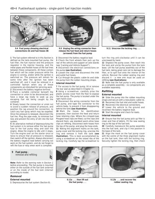
4B•4 <strong>Fuel</strong>/<strong>exhaust</strong> <strong>systems</strong> - <strong>single</strong>-<strong>point</strong> <strong>fuel</strong> <strong>injection</strong> models9.4 <strong>Fuel</strong> pump showing electricalconnections (A) and <strong>fuel</strong> hoses (B)1 The <strong>fuel</strong> system referred to in this Section isdefined as the tank-mounted <strong>fuel</strong> pump, the<strong>fuel</strong> filter, the <strong>fuel</strong> injector and the pressureregulator in the injector housing, and themetal pipes and flexible hoses of the <strong>fuel</strong> linesbetween these components. All these contain<strong>fuel</strong> which will be under pressure while theengine is running, and/or while the ignition isswitched on. The pressure will remain forsome time after the ignition has beenswitched off, and it must be relieved in acontrolled fashion when any of thesecomponents are disturbed for servicing work.2 Disconnect the battery negative terminal.3 Place a suitable container beneath theconnection or union to be disconnected, andhave a large rag ready to soak up anyescaping <strong>fuel</strong> not being caught by thecontainer.4 Slowly loosen the connection or union nutto avoid a sudden release of pressure, andposition the rag around the connection, tocatch any <strong>fuel</strong> spray which may be expelled.Once the pressure is released, disconnect the<strong>fuel</strong> line. Plug the pipe ends, to minimise <strong>fuel</strong>loss and prevent the entry of dirt into the <strong>fuel</strong>system.5 An alternative method of depressurising the<strong>fuel</strong> system is to remove either the <strong>fuel</strong> pumpfuse or the <strong>fuel</strong> pump relay and start theengine. Allow the engine to idle until it stops.Turn the engine over on the starter once ortwice to ensure that all pressure is released,then switch off the ignition. Always disconnectthe battery negative lead before carrying outwork on the <strong>fuel</strong> system, and do not forget torefit the fuse or relay when work is complete.9 <strong>Fuel</strong> pump -removal and refitting 29.9 Unplug the wiring connector thenrelease the <strong>fuel</strong> feed and return hoses(arrowed) from the <strong>fuel</strong> pump2 Disconnect the battery negative lead.3 Chock the front wheels then jack up therear of the vehicle and support on axle stands(see “Jacking and Vehicle Support”).4 Disconnect the electrical connections onthe pump (see illustration).5 Loosen the clips and disconnect the inletand outlet <strong>fuel</strong> hoses.6 Cut through the plastic cable-tie and slidethe pump from the rubber mounting straps.Internal mounted7 For access to the <strong>fuel</strong> pump, tilt or removethe rear seat as described in <strong>Chapter</strong> 11.8 Using a screwdriver, carefully prise theplastic access cover from the floor to exposethe <strong>fuel</strong> pump. The pump is located under theright-hand cover.9 Disconnect the wiring connector from the<strong>fuel</strong> pump, and tape the connector to thevehicle body, to prevent it from disappearingbehind the tank (see illustration).10 Mark the hoses for identificationpurposes, then slacken the feed and returnhose retaining clips. Where the crimped-typePeugeot hose clips are fitted, cut the clips anddiscard them; use standard worm-drive hoseclips on refitting. Disconnect both hoses fromthe top of the pump, and plug the hose ends.11 Noting the alignment marks on the tank,pump cover and the locking ring, unscrew thering and remove it from the tank (seeillustration). This is best accomplished byusing a screwdriver on the raised ribs of thelocking ring. Carefully tap the screwdriver to9.11 Unscrew the locking ring . . .turn the ring anti-clockwise until it can beunscrewed by hand.12 Displace the pump cover, then reach intothe tank and unclip the pump from the tankbase. Lift the <strong>fuel</strong> pump assembly out of the<strong>fuel</strong> tank, taking great care not to damage thefilter, or to spill <strong>fuel</strong> onto the interior of thevehicle. Recover the rubber sealing ring anddiscard it - a new one must be used onrefitting (see illustrations).13 Note that the <strong>fuel</strong> pump is only availableas a complete assembly - no components areavailable separately.RefittingExternal mounted14 Slide the pump into the rubber mountingstraps and secure with a new plastic cable-tie.15 Reconnect the <strong>fuel</strong> inlet and outlet hoses.16 Reconnect the electrical connections.17 Lower the vehicle to the ground andreconnect the battery negative lead.18 Start the engine and check for leaks.Internal mounted19 Ensure that the <strong>fuel</strong> pump pick-up filter isclean and free of debris. Fit the new sealingring to the top of the <strong>fuel</strong> tank.20 Carefully manoeuvre the pump assemblyinto the <strong>fuel</strong> tank, and clip it into position inthe base of the tank.21 Align the mark on the <strong>fuel</strong> pump coverwith the centre of the three alignment markson the <strong>fuel</strong> tank, then refit the locking ring.Securely tighten the locking ring, then checkNote: Refer to the warning note in Section 1before proceeding. The <strong>fuel</strong> pump is mountedeither on the outside of the <strong>fuel</strong> tank (external)or on the inside of the <strong>fuel</strong> tank (internal)according to model.RemovalExternal mounted1 Depressurise the <strong>fuel</strong> system (Section 8).9.12a . . . then lift outthe <strong>fuel</strong> pump . . .9.12b . . . and recover therubber sealing ring