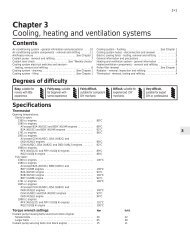
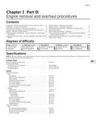
4B•8 <strong>Fuel</strong>/<strong>exhaust</strong> <strong>systems</strong> - <strong>single</strong>-<strong>point</strong> <strong>fuel</strong> <strong>injection</strong> models15.16 Disconnecting the injector wiringconnector. Injector screw is arrowedthe wiring connector from the injector wiringconnector (see illustration).17 Undo the injector cap retaining screw,then lift off the cap and recover the gasketand/or sealing ring (as applicable). Note thatas the cap screw is slackened, place a ragover the injector to catch any <strong>fuel</strong> spray whichmay be released.18 Refitting is a reversal of the removalprocedure ensuring that the injector capgasket and/or O-ring is in good condition.Take care to ensure that the cap terminals arecorrectly aligned with the injector pins andsecurely tighten the cap retaining screw.Coolant temperature sensor19 Refer to <strong>Chapter</strong> 3.Electronic control unit (ECU)20 The ECU is located in the plastic boxwhich is mounted onto the rear of the batterymounting tray.21 To remove the ECU, first disconnect thebattery.22 Unclip the cover from the box, then lift theretaining clip and disconnect the wiringconnector from the ECU.23 Undo the retaining nut and release therelay unit from the rear of the ECU box.24 Undo the retaining screws and removethe ECU and box assembly from the batterytray. If necessary, undo the retaining screwsand separate the ECU and box.25 Refitting is a reverse of the removalprocedure ensuring that the wiring connectoris securely reconnected.<strong>Fuel</strong> <strong>injection</strong> system relay unit26 The relay unit is mounted onto the rear ofthe ECU plastic box which is situated directlybehind the battery.27 To remove the relay unit, first disconnectthe battery.28 Undo the retaining nut, then disconnectthe wiring connector and remove the relay unitfrom the vehicle.29 Refitting is the reverse of removal,ensuring that the relay unit is securely clippedin position.Crankshaft sensor30 The crankshaft sensor is situated on thefront face of the transmission (clutch) housing.31 To remove the sensor, first disconnect thebattery negative terminal.32 Trace the wiring back from the sensor tothe wiring connector, and disconnect it fromthe main harness.33 Prise out the rubber grommet, then undothe retaining bolt and withdraw the sensorfrom the transmission.34 Refitting is a reverse of the removalprocedure. Ensure that the sensor retainingbolt is securely tightened, and that thegrommet is correctly seated in thetransmission housing.Vehicle speed sensor35 The vehicle speed sensor is an integralpart of the speedometer drive housing. Referto <strong>Chapter</strong> 7A, Section 7 for removal andrefitting details.16 Magneti Marelli systemcomponents - removal and 3refittingNote: Check the availability of individualcomponents with your Peugeot dealer beforedismantling.<strong>Fuel</strong> injectorNote: Refer to the warning note in Section 1before proceeding.Note: If a faulty injector is suspected, beforecondemning the injector, it is worth trying theeffect of one of the proprietary injectorcleaningtreatments. If this fails, the vehicleshould be taken to a Peugeot dealer fortesting using the appropriate specialistequipment. At the time of writing, it appearsthat neither the <strong>fuel</strong> injector nor its seals areavailable separately and, if faulty, thecomplete upper throttle body assembly mustbe renewed. Refer to your Peugeot dealer forfurther information on parts availability.1 Disconnect the battery negative terminal.2 Remove the air cleaner-to-throttle bodyduct using the information given in Section 2.3 Release the retaining tangs and disconnectthe injector wiring connector (seeillustration).4 Undo the retaining screw, then remove theretaining clip and lift the injector out of the16.3 Injector wiring connector (arrowed)housing, noting its sealing ring. Note that asthe screw is slackened, place a rag over theinjector to catch any <strong>fuel</strong> spray which may bereleased.5 Refitting is a reverse of the removalprocedure ensuring that the injector sealingring is in good condition.<strong>Fuel</strong> pressure regulatorNote: Refer to the warning note at the start ofthis Section before proceeding.Note: At the time of writing, it appears that the<strong>fuel</strong> pressure regulator is not availableseparately. If the <strong>fuel</strong> pressure regulatorassembly is faulty, the complete upper throttlebody assembly must be renewed. Refer to aPeugeot dealer for further information on partsavailability. Although the unit can bedismantled for cleaning, if required, it shouldnot be disturbed unless absolutely necessary.6 Disconnect the battery negative terminal.7 Remove the air cleaner-to-throttle bodyduct using the information given in Section 2.8 Using a suitable marker pen, makealignment marks between the regulator coverand throttle body, then undo the four retainingscrews. Note that as the screws areslackened, place a rag over the cover to catchany <strong>fuel</strong> spray which may be released.9 Lift off the cover, then remove the springand withdraw the diaphragm whilst noting itscorrect fitted orientation. Remove all traces ofdirt and examine the diaphragm for splitting. Ifdamage is found, it will be necessary to renewthe complete upper throttle body assembly asdescribed earlier in this Section.10 Refitting is a reverse of the removalprocedure ensuring that the diaphragm andcover are fitted the correct way around andthe retaining screws are securely tightened.Idle control stepper motor11 Disconnect the battery negative terminal.12 To remove the stepper motor, depress theretaining tabs and disconnect the wiringconnector. Undo the two retaining screws andwithdraw the motor from the side of thethrottle body assembly.13 Refitting is a reverse of removal.Throttle potentiometer14 Disconnect the battery negative terminal,then depress the retaining tabs anddisconnect the wiring connect from thethrottle potentiometer (see illustration).15 Undo the two retaining screws andremove the throttle potentiometer from theside of the throttle body assembly.16 Refitting is a reversal of the removalprocedure ensuring that the throttlepotentiometer tang is correctly engaged withthe throttle spindle.Inlet air temperature sensor17 The inlet air temperature sensor isscrewed into the underside of the upperthrottle body where it is situated on the lefthandside of the <strong>fuel</strong> injector.
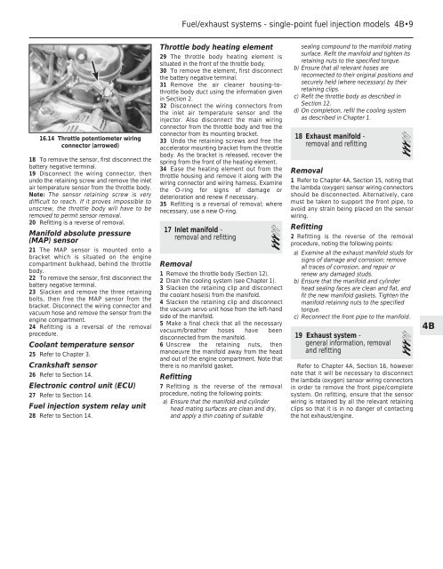
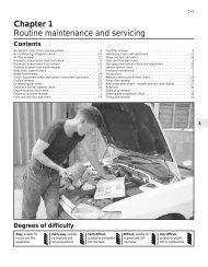
<strong>Fuel</strong>/<strong>exhaust</strong> <strong>systems</strong> - <strong>single</strong>-<strong>point</strong> <strong>fuel</strong> <strong>injection</strong> models 4B•916.14 Throttle potentiometer wiringconnector (arrowed)18 To remove the sensor, first disconnect thebattery negative terminal.19 Disconnect the wiring connector, thenundo the retaining screw and remove the inletair temperature sensor from the throttle body.Note: The sensor retaining screw is verydifficult to reach. If it proves impossible tounscrew, the throttle body will have to beremoved to permit sensor removal.20 Refitting is a reverse of removal.Manifold absolute pressure(MAP) sensor21 The MAP sensor is mounted onto abracket which is situated on the enginecompartment bulkhead, behind the throttlebody.22 To remove the sensor, first disconnect thebattery negative terminal.23 Slacken and remove the three retainingbolts, then free the MAP sensor from thebracket. Disconnect the wiring connector andvacuum hose and remove the sensor from theengine compartment.24 Refitting is a reversal of the removalprocedure.Coolant temperature sensor25 Refer to <strong>Chapter</strong> 3.Crankshaft sensor26 Refer to Section 14.Electronic control unit (ECU)27 Refer to Section 14.<strong>Fuel</strong> <strong>injection</strong> system relay unit28 Refer to Section 14.Throttle body heating element29 The throttle body heating element issituated in the front of the throttle body.30 To remove the element, first disconnectthe battery negative terminal.31 Remove the air cleaner housing-tothrottlebody duct using the information givenin Section 2.32 Disconnect the wiring connectors fromthe inlet air temperature sensor and theinjector. Also disconnect the main wiringconnector from the throttle body and free theconnector from its mounting bracket.33 Undo the retaining screws and free theaccelerator mounting bracket from the throttlebody. As the bracket is released, recover thespring from the front of the heating element.34 Ease the heating element out from thethrottle housing and remove it along with thewiring connector and wiring harness. Examinethe O-ring for signs of damage ordeterioration and renew if necessary.35 Refitting is a reversal of removal; wherenecessary, use a new O-ring.17 Inlet manifold -removal and refitting3Removal1 Remove the throttle body (Section 12).2 Drain the cooling system (see <strong>Chapter</strong> 1).3 Slacken the retaining clip and disconnectthe coolant hose(s) from the manifold.4 Slacken the retaining clip and disconnectthe vacuum servo unit hose from the left-handside of the manifold.5 Make a final check that all the necessaryvacuum/breather hoses have beendisconnected from the manifold.6 Unscrew the retaining nuts, thenmanoeuvre the manifold away from the headand out of the engine compartment. Note thatthere is no manifold gasket.Refitting7 Refitting is the reverse of the removalprocedure, noting the following <strong>point</strong>s:a) Ensure that the manifold and cylinderhead mating surfaces are clean and dry,and apply a thin coating of suitablesealing compound to the manifold matingsurface. Refit the manifold and tighten itsretaining nuts to the specified torque.b) Ensure that all relevant hoses arereconnected to their original positions andsecurely held (where necessary) by theirretaining clips.c) Refit the throttle body as described inSection 12.d) On completion, refill the cooling systemas described in <strong>Chapter</strong> 1.18 Exhaust manifold -removal and refitting3Removal1 Refer to <strong>Chapter</strong> 4A, Section 15, noting thatthe lambda (oxygen) sensor wiring connectorsshould be disconnected. Alternatively, caremust be taken to support the front pipe, toavoid any strain being placed on the sensorwiring.Refitting2 Refitting is the reverse of the removalprocedure, noting the following <strong>point</strong>s:a) Examine all the <strong>exhaust</strong> manifold studs forsigns of damage and corrosion; removeall traces of corrosion, and repair orrenew any damaged studs.b) Ensure that the manifold and cylinderhead sealing faces are clean and flat, andfit the new manifold gaskets. Tighten themanifold retaining nuts to the specifiedtorque.c) Reconnect the front pipe to the manifold.19 Exhaust system -general information, removal3and refittingRefer to <strong>Chapter</strong> 4A, Section 16, howevernote that it will be necessary to disconnectthe lambda (oxygen) sensor wiring connectorsin order to remove the front pipe/completesystem. On refitting, ensure that the sensorwiring is retained by all the relevant retainingclips so that it is in no danger of contactingthe hot <strong>exhaust</strong>/engine.4B