EZ Flow French Drain Installation Manual - NDS
EZ Flow French Drain Installation Manual - NDS
EZ Flow French Drain Installation Manual - NDS
- No tags were found...

You also want an ePaper? Increase the reach of your titles
YUMPU automatically turns print PDFs into web optimized ePapers that Google loves.
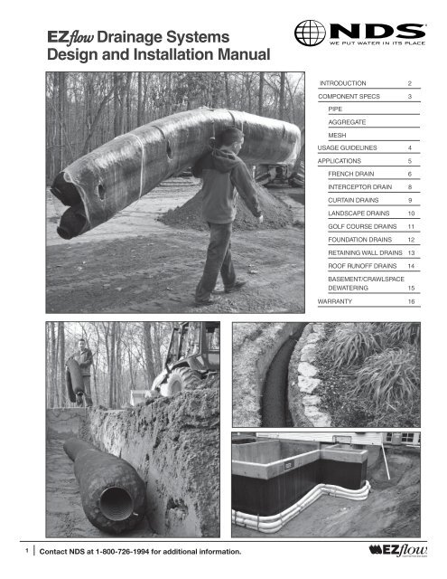
flow <strong>EZ</strong>fl w0®INTRODUCTION 2COMPONENT SPECS 3PIPEAGGREGATEMESHUSAGE GUIDELINES 4APPLICATIONS 5FRENCH DRAIN 6INTERCEPTOR DRAIN 8CURTAIN DRAINS 9LA<strong>NDS</strong>CAPE DRAINS 10GOLF COURSE DRAINS 11FOUNDATION DRAINS 12RETAINING WALL DRAINS 13ROOF RUNOFF DRAINS 14BASEMENT/CRAWLSPACEDEWATERING 15WARRANTY 161Contact <strong>NDS</strong> at 1-800-726-1994 for additional information.JULY 2010
COMPONENT SPECSf<strong>EZ</strong> lw®0The black, single-wall, corrugated flow drainage pipe isconstructed of polyethylene resins with a high recycled content,typically greater than 90%. Nominal 3-inch diameter pipe isutilized in the 7-inch bundle, 4-inch pipe in the 10-inch bundle,and 6-inch pipe in the 15-inch bundle. Slots are punched duringextrusion of the pipe, slot orientation is “random” and pipe rotationwithin each bundle is inconsequential to drainage systemfunction. The pipe is aligned either along the center axis ortouching bottom edge of the bundle, depending upon applicationand code requirements. flow drainage pipe meets ASTM F405Standard Specification for Corrugated Polyethylene (PE) Pipe andFittings. A roughness coefficient of 0.015 (Manning’s “n”) shouldbe used in flow calculations for 3- to 6-inch corrugated polyethylenepipe with a corrugated interior.The blue geosynthetic flow drainage aggregate is manufacturedfrom 100% recycled materials. Made from expandedpolystyrene (EPS), the aggregate beads have a fine to mediumcell structure and two sizes are utilized; the smaller in the 7-inchbundles and the larger in the 10- and 15-inch bundles. Bothbeads are cubical and have protuberances that provideincreased pore space and flow characteristics for drainageapplications. For storage applications, a porosity of 40% isrecommended for consolidated EPS aggregate within the bundle.The black, knit geotextile mesh sock holds the flow drainagebundle together. The 30-sieve geotextile mesh fabric used for thesock provides appropriate permeability for drainage while limitingthe migration of soils into the bundle and drainage system. Thegeotextile mesh has an apparent opening size of 0.60 mm, a unitweight between 2.5 to 3.5 ounces per square yard, and strengthof 100 pounds per square inch in accordance with ASTM D-3786.The flow rate through the geotextile mesh, as provided by themanufacturer, is 300 gallons/square foot/minute at 3 inches of headin accordance with ASTM D-4491.3 Contact <strong>NDS</strong> at 1-800-726-1994 for additional information.Contact Infiltrator Systems at 1-800-221-4436 for additional information. Page 3
APPLICATIONSf<strong>EZ</strong> lw®0Interceptor or CurtainFoundationRoof Runoff Landscape <strong>French</strong> <strong>Drain</strong> Retaining Wallflow drainage systems are appropriate for a wide range of applications and are a convenient alternative to traditional stone and pipedrainage, storage and infiltration systems. flow drainage systems can be used as a substitute for stone in most applications where thestone is not utilized for structural support. When stone does serve as structural support, such as a base course in a roadway or backfillin a mechanically-stabilized-earth retaining wall, flow should not be used. A professional engineer, landscape architect or other qualifieddesign professional should be consulted for complex applications.Product selection is relative to the desired application and benefits from establishing anticipated flow into, through and out of a proposeddrainage system configuration. Selection considerations include: bundle sizing and storage volume, the presence or absence of pipe,pipe size and location within the bundle, and arrangement of bundles. Design factors may include: length of system, watershed area,soil type and permeability, groundwater levels and system discharge opportunities. flow drainage storage volumes and pipe dischargerates are listed below. Basic product selection, system configuration considerations and installation methods are discussed in eachapplication description that follows.ProductStorage and <strong>Flow</strong> for flow <strong>Drain</strong>age Bundles (45% void space amongst consolidated EPS aggregate)Aggregate-Only BundlesStorage Volume(gallons/10-ft bundle)<strong>Flow</strong> Capacity(gpm/ft @ 1% slope)ProductPipe BundlesStorage Volume(gallons/10-ft bundle)<strong>Flow</strong> Capacity(gpm/ft @ 1% slope)<strong>EZ</strong>-0701A 701-A 8.8 37.1 <strong>EZ</strong>-0701F 701-F 11.4 80.8<strong>EZ</strong>-1001A 1001-A 17.2 75.7 1001-F/1001-FB <strong>EZ</strong>-1001F21.5 130.9<strong>EZ</strong>-1501A 1501-A 36.5 170.3 <strong>EZ</strong>-1501F/<strong>EZ</strong>-1501FB1501-F/1501-FB 45.8 345.05 Contact <strong>NDS</strong> at 1-800-726-1994 for additional information.Contact Infiltrator Systems at 1-800-221-4436 for additional information. Page 5
APPLICATIONSf<strong>EZ</strong> lw® 1. Identify the area to be drained and mark off lateral and collector lines before digging beginning trenchexcavation.2. Start excavating the trench at the discharge point or where connections to downstream piping will bemade. Trench width should be equal to the diameter of the bundle being used. Trench depth will reflectexisting 1. Identify terrain, the area desired to be drainage drained and line mark slope off and lateral length, and height collector of lines bundles(s) before and digging required beginning cover trench thickness.excavation. Ensure proper slopes by using a transit or builder’s level and grade the trench bottom evenly forproper flow.2. Start excavating the trench at the discharge point or where connections to downstream piping will bemade. Trench width should be equal to the diameter of the bundle being used. Trench depth will reflectexisting terrain, desired drainage line slope and length, height of bundles(s) and required cover thickness.Ensure proper slopes by using a transit or builder’s level and grade the trench bottom evenly forproper flow.3. Place the flow drainage bundle with pipe end to end along the edge of the trench. Use an end capat the system high point and fully insert the proper couplings at all bundle-to-bundle connections. Laythe connected bundles with pipe in trench, stacking aggregate-only bundles above these bundles asneeded.3. 4. Place a the minimum flow drainage of 4-inches bundle permeable with pipe backfill end to (see end recommended along the edge depths of the of trench. cover Use on page an end 6) over capat the the bundles system without high point compaction. and fully Additional insert the sand/backfill proper couplings can be at placed all bundle-to-bundle and compacted connections. normally above Laythe loose connected fill to prevent bundles trench with pipe saddling. trench, Cover stacking trench aggregate-only with sod or topsoil bundles and seed above to finish these installation. bundles asneeded.4. Place a minimum of 4-inches permeable backfill (see recommended depths of cover on page 6) overthe bundles without compaction. Additional sand/backfill can be placed and compacted normally abovethe loose fill to prevent trench saddling. Cover trench with sod or topsoil and seed to finish installation.0Contact Infiltrator Systems at 1-800-221-4436 for additional information. Page 77 Contact <strong>NDS</strong> at 1-800-726-1994 for additional information.Contact Infiltrator Systems at 1-800-221-4436 for additional information. Page 7
APPLICATIONSAn interceptor drain is a type of <strong>French</strong> drain that collects surface water moving downhill and/or groundwater moving horizontally in thesoil above an impervious or low-permeability layer. These drains prevent runoff and seepage from slopes onto areas below.PLACEMENTInterceptor drains should run along a contour above the area which is intended to be kept free from seepage and runoff. Interceptordrain trenches should penetrate one-half of an flow bundle diameter into the impervious layer below the water table, extend the lengthof the existing seepage line and run to daylight at a code-compliant outfall.PRODUCTThe 10-inch flow drainage bundles with integrated 4-inch pipe are appropriate for most interceptor drain situations. In conditions ofexcessive surface runoff or groundwater, or if there is over 200 feet of drain line, the 15-inch bundles with 6-inch pipe are recommended.SEEPAGE(WEEP) LINEWET AREACOARSE SAND OR PERVIOUSMATERIAL BACKFILL, 6 IN. MIN.BERM DOWNHILL SIDE OFTRENCH IN AREAS OFHIGH SURFACE RUNOFFIMPERVIOUS LAYERIMPERMEABLELINER IF NECESSARYAGGREGATE-ONLY BUNDLES,STACK AS NEEDED(TRENCH DEPTH VARIES)SURFACERUNOFFGROUNDWATERMOVEMENTTHROUGHPERVIOUSSOILSCLAY, HARDPAN,ROCK, ETC.<strong>EZ</strong>flow BUNDLE WITH PIPE- PIPE CENTER AT OR BELOWRESTRICTIVE LAYER ELEVATIONINSTALLATION INSTRUCTIONS1. Identify and mark off a hillside contour parallel with the slope to intercept surface water runoff. Lay the system out to allow for at leasttwo feet in elevation above the impervious layer causing a downgradient groundwater seep.2. Start excavating the trench at the discharge point or where connections to downstream piping will be made. The trench width shouldbe equal to the diameter of the bundle being used. The trench depth should be deep enough to excavate one-half of a bundle diameterinto the impervious layer. It may be desirable to create a small soil berm on the downhill side of the trench in areas of high surface flowto encourage runoff infiltration into the drain. Ensure proper slopes by using a transit or builder’s level and grade the trench bottom topromote the flow of collected water.3. Place the flow drainage bundles with pipe end to end along the edge of the trench. Fully insert the proper couplings at all systemconnections. An impervious liner may also be installed the full depth on the downhill side of the trench to further control seepage below.Lay the connected bundles with pipe in the trench, stacking aggregate-only bundles above the pipe-containing bundles as needed.4. Place a minimum of 6 inches of permeable backfill over the bundles without compaction. Additional sand/backfill can be placed andcompacted normally above the loose fill to prevent trench saddling. Cover trench with sod, sand or topsoil and seed to finish installation.8 Contact <strong>NDS</strong> at 1-800-726-1994 for additional information.Page 8Contact Infiltrator Systems at 1-800-221-4436 for additional information.
APPLICATIONSf<strong>EZ</strong> lw®0A curtain drain is a type of <strong>French</strong> drain that collects and diverts groundwater and surface runoff away from an area of concern, such asa septic system drainfield. For a drain field, curtain drains are useful in controlling groundwater conditions that may compromise systemfunction. flow curtain drain systems can help preserve the proper functioning of septic system drainfields.PLACEMENTCurtain drain configuration, discharge, installation depth and horizontal setback from septic system drainfields vary based upon localconditions. Curtain drains can be placed deeply to collect and divert groundwater, shallower for controlling surface runoff, or in bothconfigurations as needed. An observation port may be installed to monitor curtain drain function. An impervious liner may also be installedon the curtain drain trench sidewall as needed.PRODUCTProduct selection will vary depending on applicable codes and the amount of water to be collected and diverted. The 10-inch flowdrainage bundles with integrated 4-inch pipe are suitable for most curtain drain applications. For longer systems over 200 feet in lengththe 15-inch bundles with 6-inch pipe are recommended.SURFACE WATER SURFACE RUNOFF WATER DRAIN RUNOFF DRAINGROUNDWATER DRAIN GROUNDWATER DRAINSTABLISH VEGETATIVE ESTABLISH VEGETATIVECOVER (TYPICAL) COVER (TYPICAL)SHALLOW BERMSHALLOW BERMSURFACERUNOFFSURFACERUNOFFVEGETATIVE COVER VEGETATIVE COVERMINIMUM 6 INCHES MINIMUM 6 INCHESPERMEABLE BACKFILL PERMEABLE BACKFILLCROWN TRENCH TO CROWN TRENCPREVENT SADDLING PREVENT SADDDISTANCE TO DISTANCE TOAREA OF CONCERN AREA OF CONCERNWILL VARY WILL VARY<strong>EZ</strong>flow BUNDLEWITH PIPENATIVE SOIL<strong>EZ</strong>flow BUNDLEWITH PIPENATIVE SOILAGGREGATE-ONLY AGGREGATE-ONLYBUNDLES, STACKBUNDLES, STACKAS NEEDED AS NEEDEDGROUNDWATERMOVEMENTGROUNDWATERMOVEMENT<strong>EZ</strong>flow BUNDLE <strong>EZ</strong>flow BUNDLEWITH PIPE WITH PIPE(DEPTH VARIES) (DEPTH VARIES)IMPERMEABLE IMPERMEABLELINER AS NEEDEDLINER AS NEEDDISTANCE TO DISTANCE TOAREA OF CONCERN AREA OF CONCERNWILL VARY WILL VARYNATIVE SOIL NATIVE SOILINSTALLATION INSTRUCTIONS 1. Identify and mark off the curtain drain outline before excavation, noting the location of the area of concern, such as the septic systemdrainfield.2. Start excavating the trench at the discharge point or where connections to downstream piping will be made. The trench width shouldbe approximately equal to the diameter of the bundle being used. It may be desirable to create a small soil berm on the downhill side ofthe trench in areas of high surface flow to encourage runoff infiltration into the drain. Ensure proper slopes by using a transit or builder’slevel and grade the trench bottom evenly to promote the flow of collected water.3. Place the flow drainage pipe-containing bundles end to end along the edge of the trench. Fully insert the proper couplings at allsystem connections. An impervious liner may also be installed the full depth of the trench sidewall as needed. Lay the connected bundleswith pipe in the trench, stacking aggregate-only bundles above the pipe-containing bundles as needed.4. Place a minimum of 6 inches of permeable backfill over the bundles without compaction. Additional backfill can be placed and compactednormally above the loose fill to prevent trench saddling. Cover the trench with sod or topsoil and seed to finish the installation.9 Contact <strong>NDS</strong> at 1-800-726-1994 for additional information.Contact Infiltrator Systems at 1-800-221-4436 for additional information. Page 9
APPLICATIONSf<strong>EZ</strong> lw®0flow drainage systems are ideal for draining wet areas around the course and for installation of drainage systems on fairway andgreenside bunkers.PLACEMENTGolf course drainage will generally follow the same placement recommendations as for <strong>French</strong> drain systems with special considerationsfor sand trap bunkers. Sand trap drainage trenches should be dug so that the top of the flow drainage bundle rests 1 to 2 inchesbelow the bunker bottom to allow for maximum sand cover. Cleanout ports are recommended for bunker drainage systems at an accessibleend of the main drain line.PRODUCTThe 10-inch bundles with integrated 4-inch pipe are suitable for most sand trap bunker applications. For main drain lines in large bunkersconsider an additional outlet or using the 15-inch bundles with integrated 6-inch drain pipe. Follow the <strong>French</strong> drains product guidelinesfor general wet area drainage.PUTTING GREENSAND TRAP BUNKERPUTTING SURFACEROOT ZONE MEDIACOARSE SANDPEA GRAVELBUNKERBOTTOM4" TO 6" SAND<strong>EZ</strong>flowBUNDLEWITH PIPE12"<strong>EZ</strong>flowBUNDLEWITH PIPE12"1" - 2" MAX.INSTALLATION INSTRUCTIONS WET AREASFollow the general french drain installation instructions on Page 7 for flow drainage installation in wet areas around the golf course.SAND TRAP BUNKER1. Identify the slowest drainage areas of the sand trap and determine the pattern for the drain line: irregular, herring bone or gridiron(see french drains drainage drainage patterns patterns). on page 6)2. Remove the sand from the areas of the bunker along the proposed trenches. Start digging the trench at the discharge point or whereconnections to downstream piping will be made to receive the 10-inch flow drainage bundles with pipe. Trench width should be aminimum of 12 inches to allow for an inch of sand on either side, with a maximum depth of 11 to 12 inches.3. Place the flow bundles with pipe end to end along the edge of the trench. Use an end cap at the system high point and fully insertthe proper couplings at all bundle-to-bundle connections. Lay the connected bundles with pipe in the trench and cover with the removedsand. Sand can be “walked” into the trench to ensure proper fill.PUTTING GREENSPlease contact <strong>NDS</strong> Infiltrator 1-800-992-9949 Systems at 800.221.4436 x2145 for design for design consultation consultation when considering when considering using <strong>EZ</strong>flow using flow drainage drainage systems systems in putting in puttinggreen applications.11 Contact <strong>NDS</strong> at 1-800-726-1994 for additional information.Contact Infiltrator Systems at 1-800-221-4436 for additional information. Page 11
APPLICATIONSFoundation and footing perimeter drainage systems prevent moisture from entering a building basement or crawlspace throughinterception and removal. Aggregate-only flow drainage bundles stacked along the foundation wall face within 18 inches of exteriorfinished grade will intercept groundwater effectively and drain to a bundle with pipe below.PLACEMENTIdeal placement for the flow drainage bundle with pipe in a foundation drain is at the footing toe along the entire building foundationperimeter, or at a minimum, below the finished grade elevation of the interior basement or crawlspace. The drain should have a continuousslope and outlet that runs to the drainage point. The system outlet should slope greater than the footing perimeter drain and have a diameterequal to or preferably greater than that of the drain pipe. PRODUCTThe flow 10-inch drainage bundles with integrated 4-inch pipe are suitable for most foundation conditions. If there is over 200 feet offooting or high groundwater conditions, consider an additional outlet or using the 15-inch bundles with integrated 6-inch drain pipe.FINISHED GRADE FINISHED GRADEEXTERIOR EXTERIORAGGREGATE-ONLY BUNDLES TO WITHINAGGREGATE-ONLY BUNDLES 18 IN. OF FINISHED TO WITHIN GRADE (TYPICAL)18 IN. OF FINISHED GRADE (TYPICAL)LOCATE <strong>EZ</strong>flow BUNDLE WITH PIPE ATLOCATE <strong>EZ</strong>flow FOOTING BUNDLE TOE WITH OR, PIPE AT A MINIMUM, AT BELOWELEVATION OF INTERIOR FINISHED GRADEFOOTING TOE OR, AT A MINIMUM, BELOWOF BASEMENT/ CRAWLSPACE AND SLOPEELEVATION OF INTERIOR FINISHED GRADETO DISCHARGE PONTOF BASEMENT/ CRAWLSPACE AND SLOPETO DISCHARGE PONTFOUNDATION FOUNDATION WALL WALLINTERIORINTERIOR(SEE BASEMENT/(SEE BASEMENT/ CRAWL SPACECRAWL SPACE DRAIN DETAIL)DRAIN DETAIL)FINISHED GRADEFINISHED INTERIOR GRADEINTERIORFOOTINGFOOTINGALTERNATE ALTERNATECONFIGURATIONCONFIGURATIONINSTALLATION INSTRUCTIONS1. Starting at the discharge point or where connections to downstream piping will be made,place the flow drainage bundles with pipe next to the foundation footing, or at a minimumbelow the basement or crawlspace finished floor elevation, but at a maximum of 12 feet. Thebundles must run along the entire footing perimeter and be placed upon a prepared subgradebase sloped evenly to drain. Use an end cap at any high point and fully insert proper couplingsat all system connections.2. Place aggregate-only bundles above and touching the pipe-containing bundle, ensuring hydraulicconnectivity over the footing. Place additional aggregate-only bundles up the foundationwall to the desired height, generally within 18 inches of finished grade. Bundles can be held inplace with stakes as needed prior to backfilling. Avoid tearing the mesh fabric when staking.3. Backfill the foundation excavation according to the site plans. Make sure that no large stonesor debris are in contact with the flow drainage system.12 Contact <strong>NDS</strong> at 1-800-726-1994 for additional information.Page 12Contact Infiltrator Systems at 1-800-221-4436 for additional information.
APPLICATIONSf<strong>EZ</strong> lw®0Retaining walls work to hold back earth in the landscape. Hydrostatic pressure from groundwater can cause even low retaining walls tofail, so drainage is critical to wall longevity. Also, groundwater weeping through dry-stacked masonry or timber pile retaining walls cancause unsightly staining and streaking. Similar to their function in foundation and footing drains, flow drainage systems intercept andconvey groundwater from behind a retaining wall, relieving hydrostatic pressure and preventing weeps.PLACEMENTDepending on retaining wall design and groundwater conditions, flow drainage bundles can be placed at the base of the wall footingor stacked on the backside of the wall.PRODUCTflow drainage bundle selection for most gravity and piling retaining wall applications should correspond to the diameter of pipe andarrangement of drainage aggregate specified on approved plans.INSTALLATION INSTRUCTIONS flow flow flow 1. Starting at the discharge point or where connections to downstream piping will be made,place the flow bundles with pipe next to the retaining wall footing in gravity walls, or at a minimumbelow the finished grade elevation in front of the wall. In piling walls, place the bottombundle behind the wall at an elevation equal to the finished grade elevation in front of the wall.Use an end cap at any system high point and fully insert the proper couplings at all systemconnections.2. Place aggregate-only bundles above and touching the bottom pipe-containing bundle,ensuring hydraulic connectivity over the footing and up the foundation wall to the desired height,generally within 18 inches of finished grade. Bundles can be held in place with stakes asneeded prior to backfilling. Avoid tearing the mesh fabric with stakes.3. Backfill the retaining wall excavation according to the site plans. Make sure that no largestones or debris are in contact with flow drainage system.13 Contact <strong>NDS</strong> at 1-800-726-1994 for additional information.Contact Infiltrator Systems at 1-800-221-4436 for additional information. Page 13
APPLICATIONSRoof runoff drains divert rainwater collected in a gutter system away from the building foundation. Systems can be designed to allow formaximum groundwater recharge and to discharge peak flows into the landscape.PLACEMENTRoof runoff systems should not drain toward building foundations or retaining walls so as not to increase hydrostatic pressure on theseelements or overload their relative drainage systems.Gutter drain systems should utilize <strong>EZ</strong>flow flow drainage bundles starting a minimum 4 ft. from and aligned away from the building foundation.Catch <strong>NDS</strong> catch basins basins combined combined with with solid solid (unperforated) pipe systems and bends can receive direct gutter flow flow and and convey it to it the to the <strong>EZ</strong>flow flowdrainage bundles. Gutter drain systems should then then discharge to a to pop-up a pop-up emitter, emitter, surface surface swale, swale, core-drilled core-drilled curb curb or other or other discharge dischargepoint. Stacking aggregate-only bundles to to the seasonal high groundwater level level in in the the soil soil below the the main main receiving bundles will will maximizegroundwater recharge and limit peak outflows.PRODUCTIn general, flow drainage bundles should be selected with a pipe diameter equal to or greater than the size of the downspout. If twoor more downspouts are connected to drain into one flow drainage bundle, the 15-inch bundle with 6-inch pipe should be utilized.ROOFGUTTERDOWNSPOUT<strong>EZ</strong>flow DRAINAGE BUNDLES WITH PIPESLOPE AT 1% MIN. AND PROVIDE COVERPER CHARTEXAMPLECONFIGURATIONS4 FT. MIN.CATCH BASIN(RECOMMENDED)ARRANGE AGGREGATE-ONLY BUNDLESBELOW MAIN BUNDLE TO THE SEASONALHIGH GROUNDWATER LEVEL FOR MAXIMUMGROUNDWATER RECHARGE - BUNDLECONFIGURATIONS MAY VARYSEASONAL HIGH GROUNDWATER LEVELDRAIN TO SURFACE SWALE, POP-UP EMITTER, CORE-DRILLED CURBOR OTHER APPROVED OUTFALLMINIMUM SOIL COVER IN VERTICAL STACKROOF RUNOFF APPLICATIONSNo. of 10” BundlesMinimum Soil Cover1 or 2 6”3 8”4 10”5 12”INSTALLATION INSTRUCTIONS 1. Identify downspout locations for connection to the proposed roof runoff system. Mark off areas for connection piping and for the flowdrainage bundles, considering system discharge limitations.2. Excavate locations for catch basins, pipe runs and bundles. The trench for the flow drainage bundles should match the bundlewidth and can be excavated to the seasonal high groundwater level for maximum groundwater recharge.3. Install aggregate-only flow drainage bundles along the bottom of the deep trench as needed for maximum groundwater recharge,and the pipe-containing bundle with pipe at the appropriate depth to ensure a minimum 4 inches of soil cover above the system.4. Install an <strong>NDS</strong> or equivalent catch basin to directly receive downspout discharge and run a minimum 4-foot length of solid (unperforated)pipe away from the building foundation before connecting to the flow drainage pipe. More than one downspout can beconnected prior to entering the system with properly-sloped solid piping and connections. Catch basins are recommended for ease ofmaintenance. Clean-outs must be installed if direct downspout to drainage system connections are made.5. Following the flow drainage bundle assembly, install a solid pipe run to a pop-up emitter, surface swale, core-drilled curb or otherdrainage point. Fully insert the proper couplings at all system connections.6. Cover the trench and other exposed excavation areas with sod or topsoil and seed to finish the installation.14 Contact <strong>NDS</strong> at 1-800-726-1994 for additional information.Page 14Contact Infiltrator Systems at 1-800-221-4436 for additional information.
APPLICATIONSf<strong>EZ</strong> lw®0In many cases older homes were constructed without foundation and footing perimeter drains. A basement area or crawlspace can becomeinundated when groundwater levels rise with seasonal cycles or following heavy rains. Retrofitting a footing drain on an existinghome can be impractical considering paved areas, steps, decks and patios, site access, utility connections and mature landscaping. Abetter solution may be to install an interior basement or crawlspace drain system that conveys collected water to a discharge point orsump for removal from basement or crawlspace by pump.PLACEMENTFor flow drainage basement and crawlspace dewatering systems it is recommended that a 10- to 12-inch-wide trench be excavatedalong the interior foundation wall a minimum of 9 inches deep below the floor surface elevation for a soil floor or 9 inches below thebottom of floor slab elevation for a concrete floor. The trench must slope towards and discharge into an excavated sump. <strong>Installation</strong>should be avoided during flooded conditions or when no other outlet exists.PRODUCT7-inch flow drainage bundles with 3-inch pipe are installed along the bottom of the trench with appropriate fittings at trench bends. Aminimum 2-inch layer of permeable backfill is placed above the bundle to support poured concrete in slab repair situations or broughtto finished grade where the concrete slab exists.OPTIONAL REPAIRED SLABTO MATCH EXISTING OR COARSESAND/PEA STONE TO INTERIORFINISHED GRADECOARSE SANDOR PEA STONE(2 INCHES, MIN.)FOUNDATION WALLEXISTING INTERIORCONCRETE SLAB(IF PRESENT)FOOTINGMOISTURE BARRIER<strong>EZ</strong>flow 7-INCH BUNDLE WITH 3-INCH PIPE,DRAIN TO EXCAVATED SUMP AND PUMPTO APPROVED EXTERIOR OUTFALLUNDISTURBED SUBGRADEINSTALLATION INSTRUCTIONS1. Excavate a trench along the inside perimeter of the foundation wall being careful to not damage or interfere with existing utilities. Thetrench should be a minimum of 9 inches deep and should be sloped evenly towards an excavated sump or discharge point.2. Connect the 7-inch flow bundle with 3-inch pipe to the excavated sump outfall and connect additional bundles to run the entirelength of the trench. Use an end cap at any system high point and fully insert the proper couplings at all system connections.3. Place a minimum 2-inch layer of clean, coarse sand or washed pea gravel above the bundle to support poured concrete in slab repairsituations, or place the sand/gravel to finished grade where no concrete slab exists.15 Contact <strong>NDS</strong> at 1-800-726-1994 for additional information.Contact Infiltrator Systems at 1-800-221-4436 for additional information. Page 15
<strong>NDS</strong> <strong>EZ</strong>FLOW WARRANTYSTANDARD LIMITED WARRANTY(a) The structural integrity of each <strong>EZ</strong><strong>Flow</strong> expanded polystyrene drainage system manufactured by <strong>EZ</strong><strong>Flow</strong>LP and distributed by National Diversified Sales, Inc. (“<strong>NDS</strong>”), when installed and operated in a drainagesystem in accordance with its instructions, is warranted to the original purchaser (“Holder”) against defectivematerials and workmanship for one year from the date installation of the drainage system commences. Toexercise its warranty rights, Holder must notify <strong>NDS</strong> in writing at its Corporate Headquarters, 21820 BurbankBlvd., Suite 200, Woodland Hills, CA 91367 within fifteen (15) days of the alleged defect. <strong>EZ</strong><strong>Flow</strong> LPwill supply replacement Units for Units determined by <strong>EZ</strong><strong>Flow</strong> LP to be covered by this Limited Warranty.The liability of <strong>EZ</strong><strong>Flow</strong> LP and <strong>NDS</strong> specifically excludes the cost of removal and/or installation of the Units.(b) THE LIMITED WARRANTY AND REMEDIES IN SUBPARAGRAPH (a) ARE EXCLUSIVE. THERE ARE NOOTHER WARRANTIES WITH RESPECT TO THE UNITS, INCLUDING NO IMPLIED WARRANTIES OF MER-CHANTABILITY OR FITNESS FOR A PARTICULAR PURPOSE(c) The Limited Warranty does not extend to incidental, consequential, special or indirect damages.<strong>EZ</strong><strong>Flow</strong> LP and <strong>NDS</strong> shall not be liable for penalties or liquidated damages, including loss of production andprofits, labor and materials, overhead costs, or other losses or expenses incurred by the Holder or any thirdparty. Specifically excluded from Limited Warranty coverage are damage to the Units due to ordinary wearand tear, alteration, accident, misuse, abuse or neglect of the Units; the Units being subjected to vehicletraffic or other conditions which are not permitted by the installation instructions; failure to maintain the minimumground covers set forth in the installation instructions; failure of the Units due to improper sitting or impropersizing; or any other event not caused by <strong>EZ</strong><strong>Flow</strong> LP or <strong>NDS</strong>, This Limited Warranty shall be void if theHolder fails to comply with all of the terms set forth in this Limited Warranty. Further, in no event shall <strong>EZ</strong><strong>Flow</strong>LP or <strong>NDS</strong> be responsible for any loss or damage to the Holder, the Units, or any third party resulting frominstallation or shipment, or from any product liability claims of Holder or any third party.(d) No representative of <strong>EZ</strong><strong>Flow</strong> LP or <strong>NDS</strong> has the authority to change or extend this Limited Warranty. Nowarranty applies to any party other than the original Holder.10.2010