Regloplas- Temperiertechnik
Regloplas- Temperiertechnik
Regloplas- Temperiertechnik
- No tags were found...
You also want an ePaper? Increase the reach of your titles
YUMPU automatically turns print PDFs into web optimized ePapers that Google loves.
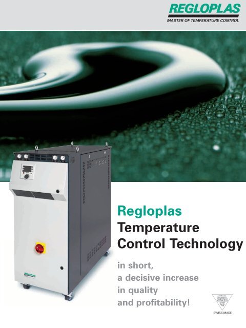
<strong>Regloplas</strong> has specializedin building temperaturecontrol unitsfor more than 50 years.
This specialization bringssignificant advantages forthe customer: the availabil -ity of extensive knowledge inconsultation, developmentand application of units.<strong>Regloplas</strong> Swiss qualityproducts are in successfuluse in over 50 countries.Close cooperation between our clients,representatives and specialists result insuccessful designs truly suited to theapplications.ContentsPage4Temperature control unitsfor water up to 90 °C orthermal oil up to 150 °C90smart/90S90XL150smart/150S1508Pressurised-water temperaturecontrol units up to 180 °CP100MP140smartP160SP160M(D)P161XLP180SP180M(D)12161820232431Temperature control units forfor thermal oil up to 350 °CControlWater cooling unitsServiceNotes on technical dataAccessoriesService300smart300S300L(D)350L(D)RT100RT50RT61RT32RC2E7 – RC2E60/ZRCWE7 – RCWE55REG/REM93RK93SR80NotesAccessoriesServiceSubject to change without notice3
Temperature control unitsfor water up to 90 °Cor thermal oil up to 150 °CTemperature control of injection moulds, extruders,rollers, vessels and other applications.Additional advantages:Minimal reject rates beginning at productionstart-up. Better cavity-filling performance. Closertolerances. Minimizes warping and shrinkage. Bettersurface finish. Continuous high-quality production.In the manufacture of injectionmoulded parts, correct mouldtemperatures can reduce rejectrates by 24% and improve productivityby up to 20% (Researchreport by the Aachen TechnicalUniversity/Germany).4
Standard equipmentElectrical section• RT32 controller, RT50 or RT61 control system‘ Optimal fit for practically every application.• Electric control in accordance with IECstandards. Tropic-proof up to 90% humidity.Completely separated from the pumpingsection and protected against direct contact‘ Safe operation.90smart90S90XL150smart150S150Mechanical section• Tank made of stainless steel‘ Long service life.• Water circuit made of non-ferrous materials.• High-performance centrifugal pump andmotor for circulation of the thermal oil evenat low temperatures ‘ Safe operation.• Low thermal load of the fluid, short circulat -ing time ‘ Long service life of the heattransfer oil, good control performance.• Heater elements for high corrosion resis t -ance ‘ Long service life.• Filter in cooling water inlet.Safety• Safety thermostat ‘ Protection againstoverheating.• Automatic fluid level control‘ Protection against running dry.• Acoustic common alarm (150: optional).Small-unit assembly: From standard units to special designs,<strong>Regloplas</strong> offers customised solutions.Unit-specific equipmentEquipment 90smart 90S 90XL 150smart 150S 150Control system RT50 (options see page 17) – ° ° – ° °Control system RT61 (options see page 17) • – – • – –Controller RT32 (options see page 17) – ° ° /– – ° °Solid-state Relay (SSR) instead of heating contactor • ° ° • ° °Electronic flow measurement° ° ° ° ° °Manual shut-off valve in the inlet and outlet – ° • – ° °Adjustable bypass for regulation of the flow ratein the consumer– – • – – –Leak-free pump • • ° • • •Automatic water refill • • • •/– – –Unit in IP54 protection degree – – • – – –Direct cooling – – • – – –• Standard equipment° Option – Not available •/–; ° /– Unit-specific Further options available upon request5
Technical data 90smart 90S 90XL 150smart 150S 150Outlet temperature max. °C 90 90 90 150 90 150 1 150 2Heat transfer fluid Water Water Water Oil Water Oil OilFilling quantity l 6,5 6,0 36,5 12,0 12,0 17,6Expansion volume l 3,2 3,4 5,5 4 4 6Heating capacity at 400 V kW 9 6; 9 20; 40; 60 6 6 12Cooling capacity kW 24 76 38 58 160 28 31 28 58 70at outlet temperature °C 90 90 80 80 80 140 90 140 140 60Cooler (K) 1 2 1 2 DK 1 1 1 1 2Diagram (Fig.) 1 1 2 3 1 3 3Pump capacityTP20 TP20 TS22 CR10-4 TP20 TP20 TS22 TP20 TS22Flow rate max. l/min 60 60 70 200 60 60 70 60 70Pressure max. bar 3,8 3,8 5,4 4,4 4 3,8 3,8 5,4 3,8 5,4Power consumption kW 0,5 0,5 1,1 1,5 0,5 0,5 1,1 0,5 1,1Diagram (Fig.) 4 4 5 4 4 4Control RT61 RT32 RT50 RT32 3 RT50 RT61 RT32 RT50 RT32 RT50Measuring mode (Standard) Pt100 Pt100 Pt100 Pt100 Pt100 Pt100Operating voltage (Standard) V/Hz 400/50, 3 PE 400/50, 3 PE 400/50, 3 PE 400/50, 3 PE 400/50, 3 PE 400/50, 3 PEConnections Outlet/inlet G 1 ⁄2” G 1 ⁄2” G1 1 ⁄2” IG G 1 ⁄2” G 1 ⁄2” M26 x 1,5Cooling water mains G 3 ⁄8” G 1 ⁄2” G 3 ⁄4” G 3 ⁄8” G 1 ⁄2” G 1 ⁄2”Dimensions W/H/D mm 228/565/640 200/557/666 436/1357/1349 228/612/698 200/653/697 346/690/728Weight approx. kg 32 44 229 41 50 78Colour grey 9006/7016Ambient temperature max. °C 40Noise level dB(A) < 70Notes 1Optional up to 180 °C. Only with pump TS22H. DK: Direct cooling2Optional up to 200 °C. Only with pump TS22H. G: Parallel thread390XL only with 20 kW heating capacity. IG: Female thread4Values at 50 Hz.Cooling capacity P as a function ofoutlet temperature ϑ.Cooling water data:Inlet temperature 20 °C/90smart 15 °C.Flow rates:90S/1K; 150smart; 150S: 10 l/min90smart; 90S/2K; 150: 20 l/min90XL:36 l/min9.009778-19.009778-29.009778-3Fig. 1: Fluid water90smart; 150smart; 90S1 90smart 1K2 90smart 2K3 90S 1K4 90S 2K5 150smart 1KFig. 2: Fluid water90XL1 90XL DKFig. 3: Fluid oil150smart; 150S; 1501 150smart 1K150S 1K2 150 1K3 150 2K6
Pump capacity. Flow rate Vas a function of pressure p.Bypass not included.90smart90S90XL150smart150S1509.009775-19.009775-3Fig. 4: 90smart; 90S; 150smart;150S; 1501 TP202 TS22; TS22HFig. 5: 90XL1 CR10-4Fig. 6: Principle 90smart; 150smart. Water9.008954AFig. 7: Principle 90S9.005735A36 Filter main circuit38 Tank41 Cooler58 Bypass60 Filter cooling circuit61 Pressure gauge74 Hand valve99 ConsumerB1 Temperature sensor internalE21 HeaterF5 Safety thermostatM10 PumpS1 Level controlY2 Solenoid valve, automaticwater refillY6 Solenoid valve, coolingY13 Solenoid valve, consumerdrainage9.000471A9.005895AFig. 8: Principle 90XL DKFig. 9: Principle 150smart; 150S; 150. Oil7
Pressurised-watertemperature controlunits up to 180 ° CTemperature control of plastic injection moulds,diecasting dies, rollers, extruders, mixers and otherapplications.Superior heat transfer has a direct effect upon theoutput of your production plant.Pressurised water units canbe implemented wherever thereare advantages of water as aheat transfer fluid.Patented low-scale coolingsystem “SK”.8
Standard equipmentElectrical section• RT100 or RT61 control system ‘ Optimal fitfor practically every application.• Electric control in accordance with IECstandards. Tropic-proof up to 90% humidity.Completely separated from the pumpingsection and protected against direct contact‘ Safe operation.Mechanical section• Operating temperature independent ofcooling water pressure ‘ Flexible operation.• All components exposed to water are madeof non-ferrous materials. Tank made of stainlesssteel. ‘ Long service life.• Heating elements made of heat-resistantalloy Incoloy ® for high corrosion resistance‘ Safe operation, long service life.• Sturdy and powerful centrifugal pump highcapacity ‘ Quick compensation of disturb -ances, good regulating performance.• Filter in cooling water inlet.• Low-scale, dual-circuit cooling system“SK/2SK” ‘ Significant reduction of scalingin the cooler (not available for theP140smart).• Automatic water refill.• Leak-free Pump (except SG85)Safety• Safety valve ‘ Prevents excessivepressure in the unit.• Pressure gauge for system pressure.• Safety thermostat ‘ Protection againstoverheating.• Automatic fluid level control‘ Protection against running dry.• Acoustic common alarm.P100MP140smartP160SP160M(D)P161XLP180SP180M(D)Quality assurance: At <strong>Regloplas</strong>, all units, whether standard orcustomised, undergo all phases of rigorous final testing.Unit-specific equipmentEquipment P100M P140smart P160S P160M(D) P161XL P180S P180M(D)Control system RT100 (options see page 17) • – • • • • •Control system RT61 (options see page 17) – • – – – – –Solid-state Relay (SSR) instead of heating contactor • • • • • • •Electronic flow measurement° ° ° ° ° ° °Manual shut-off valve in the inlet and outlet° – ° ° • ° °Inlet filter • ° • • • • •Display of outlet pressure on RT100° – • • • • •Drainage of the fluid from the consumer by suction° ° • • – • •Patented low-scale cooling system “SK” – – • • • • •Unit in IP54 protection degree • – • • • • •• Standard equipment°Option – Not available Further options available upon request9
Technical data P100M P140smart P160S P160M(D) P161XL P180S P180M(D)Outlet temperature max. °C 100 140 160 2 160 3 160 4 180 180Heat transfer fluidFilling capacityExpansion volumellWater1–Water40,5Water1–Heat capacity at 400 V kW 8; 18 9 8 8; 18 1 20; 40; 60 8 8; 18 1Cooling capacity typeat outlet temperatureCooler (K)Diagram (Fig.)Pump capacity/typeFlow ratemax.Pressuremax.Power consumptionDiagram (Abb.)ControlMeasuring mode (Standard)kW°Cl/minbarkW160 60 7890 90 90DK 1 23 2 2SM72606,015RT100Pt1003513011SM22 SM5140 455,5 7,00,5 1,04RT61Pt10039150SK1SM23405,50,54RT100Pt100Water1–66 1 78 1150 150SK 1 2SK 12 2SM73 7560 1 100 16,0 1 6,0 11,5 1 1,5 15 5Water105135150SK3SM852008,04,06Water1–45170SK1SM23H405,50,54Water1–76 1 90 1170 170SK 1 2SK 12 2SM73H 75H60 1 100 16,0 1 6,0 11,5 1 1,5 15 5Operating voltage(Standard) V/Hz 400/50, 3 PE 400/50, 3 PE 400/50, 3 PE 400/50, 3 PE 400/50, 3 PE 400/50, 3 PE 400/50, 3 PEConnectionsOutlet/InletCooling water mainsG 3 ⁄4”G 1 ⁄2”G 1 ⁄2”G 3 ⁄8”G 1 ⁄2”G 1 ⁄2”RT100Pt100G 3 ⁄4”G 1 ⁄2”RT100Pt100G1 1 ⁄2” IGG 3 ⁄4”Dimensions W/H/D mm 300/708/896 228/612/706 236/589/812300/708/896300/708/896436/1357/1544 236/589/812416/1556/1037(D)416/1556/1037(D)Weight approx. kg 70 45 52 84/170(D) 275 52 84/170(D)Colour grey 9006/7016Ambient temperaturemax. °C 40Noise level dB(A) < 70Notes 1Per zone D: Dual zone unit2Optional up to 140°C. Only with pump SM 22. Order Text: P140S/... G: Parallel thread3Optional up to 140°C. Only with pump SM 72. Order Text: P140M/... (only single zone unit) IG: Female thread4Optional up to 140°C. Only with pump SG 85. Order Text: P141XL/... SK: Low-scale coolerDK: Direct coolingRT100Pt100G 1 ⁄2”G 1 ⁄2”RT100Pt100G 3 ⁄4”G 1 ⁄2”Cooling capacity P as a function ofoutlet temperature ϑ.Cooling water data: Inlet temperature +20 °C.Flow rates:P140smart:P100M; P160S; P160M(D); P180S; P180M(D)P161XL:10 l/min20 l/min30 l/min9.009781-5C9.009781-2C9.009781-3CFig. 1: P140smart; P160S1 P140smart 1KP160S SK2 P180S SK10Fig. 2: P160M(D); P180M(D)1 P160M(D) SKP180M(D) SK2 P160M(D) 2SKP180M(D) 2SK3 P100M 1K4 P100M 2KFig. 3: P141XL; P161XL1 P161XL SK2 P100 DK
Pump capacity. Flow rate Vas a function of pressure p.Bypass not included.P100MP140smartP160SP160M(D)P161XLP180SP180M(D)9.009776-4A9.009776-SA9.009776-3Fig. 4: P140smart; P160S1 SM22; SM23; SM23H2 SM51Fig. 5: P100M; P160M(D); P180M(D)1 SM72; SM73; SM73H2 SM75; SM75HFig. 6: P161XL1 SG/SM85Fig. 7: Principle P100M with cooler «DK»Fig. 9: Principle P140smart9.010954C9.002154CFig. 8: Principle P100M with cooler «1K/2K»Fig. 10: Principle P160S; P180S; P160M(D);P180M(D) with cooler «SK»9.011421C9.010133-1A36 Filter main circuit38 Tank41 Cooler53 Expansion valve56 One-way check valve57 Safety valve58 Bypass60 Filter cooling circuit65 Water hammer arrester61 Pressure gauge74 Hand valve99 ConsumerB1 Temperature sensor internalB8 Pressure sensor SystempressureB8,1 Pressure sensoroutlet-pressureE21 HeaterF5 Safety thermostatM1 Cooling pump (cooler “SK”)M2 Filling pumpM10 PumpS1 Level controlY2 Solenoid vave,automatic water refillY2.1 Solenoid valve, water refill(pressure control)Y6 Solenoid valve, coolingY8 Solenoid valve,pressure releaseY8.1 Solenoid valve additionalpressure releaseY13 Solenoid valve, consumerdrainage9.005393BFig. 11: Principle P161XL with cooler «SK»11
Temperature control unitsfor thermal oilup to 350 °CTemperature control of diecasting dies, extruders,rollers, mixers, vessels and other applications.In the production of diecasting parts<strong>Regloplas</strong> temperature controlunits can reduce reject ratesup to 80%, and make thedie last up to 3 times longer,reducing heat-up time byas much as 30%.12
Standard equipmentElectrical section• RT100, RT50 or RT61 control system ‘Optimal fit for practically every application.• Electric control in accordance with IECstandards. Tropic-proof up to 90% humidity.Completely separated from the punping sectionand protected against direct contact‘ Safe operation.Mechanical section• Pump: With magnetic drive ‘ Leak-freeoperation due to elimination of themechanical seal.High capacity ‘ Quick compensation ofdisturbances, good regulating performance.• Separate expansion vessel ‘ Reducesoxidation as the circulating hot oil is separatedfrom the atmosphere by the stationary oilin the expansion vessel. Also emission ofcombustible oil vapors into the atmosphereis avoided.• One-way check valve in cooling water outlet‘ Reduces the possibility of scale in thecooler by back-flow water.• Filter in cooling water inlet.• Bypass for internal circulation of the oil incase of insufficient flow, e.g. when the consumeris blocked ‘ Avoids thermal over -loading of the oil.Safety• Safety thermostat ‘ Protection againstoverheating.• Automatic fluid level control ‘ Protectionagainst running dry.• Flow monitor ‘ Protection against runningdry and overheating of the oil.• Pressure gauge in the outlet and inlet.• Acoustic common alarm.300smart300S300L(D)350L(D)Mechanical assembly: Expertise and precision assure the high qualityof our products.Unit-specific equipmentEquipment 300smart 300S 300L(D) 350L(D)Control system RT100 (options see page 17) – – • •Control system RT50 (options see page 17) – • – –Control system RT61 (options see page 17) • – – –Solid-state Relay (SSR) instead of heating contactor • ° • •Unit in IP54 protection degree – ° • •Second level – ° • •Cooler with bypass circuit ‘ Significantly better regulatingbehaviour, reduced possibility of scaling– – ° °Inert gas blanket ‘ Longer oil life– – – °Electronic flow measurement° ° ° °• Standard equipment°Option – Not available Further options available upon request13
Technical data 300smart 300S 300L(D) 350L(D)Outlet temperature max. °C 300 300 350 350Heat transfer fluid Oil Oil Oil OilFilling quantity l 6 6 15 24 15 24Expansion volume l 7 7 20 20Heating capacity at 400 V kW 6 6 20; 40 1 20 1Cooling capacity kW 70 70 160 1 80 1at outlet temperature °C 280 280 280 280Cooler (K) 1 1 1 1 1 1Diagram (Fig.) 1 1 1 2Pump capacity/type FM25 FM25 FM65 FM65Flow rate max. l/min 45 45 90 1 90 1Pressure max. bar 7.0 7.0 10.0 1 10,0 1Power consumption kW 1.0 1.0 2.8 1 2,8 1Diagram (Fig.) 3 3 3 3 1Control RT61 RT50 RT100 RT100Measuring mode (Standard) Pt100 Pt100 Pt100 Pt100Operating voltage (Standard) V/Hz 400/50, 3 PE 400/50, 3 PE 400/50, 3 PE 400/50, 3 PEConnections Outlet/Inlet G 1 ⁄2” G 1 ⁄2” G 3 ⁄4” IG G 3 ⁄4” IGCooling water mains G 1 ⁄2” G 1 ⁄2” G 3 ⁄4” G 3 ⁄4”Dimensions W/H/D mm 316/756/897 316/756/897 436/1357/1474 546/1627/1442546/1357/1474(D)Weight approx. kg 87 87 246 310365(D)642(D)Colour grey RAL 9006/7016Ambient temperature max. °C 40Noise level dB (A) < 70Notes1Per zoneD: Dual zone unitG: Parallel threadIG: Female threadCooling capacity P as a functionof outlet temperature ϑ.Cooling water data:Inlet temperature +20 °CFlow rate per zone 20 l/min9.009782-19.009782-2-1AFig. 1: 300smart; 300S; 300L(D)1 300smart 1K300S 1K2 300L(D) 1KFig. 2: 350L(D)1 350L(D) 1K14
Pump capacity. Flow rate Vas a function of pressure p.Bypass not included.300smart300S300L(D)350L(D)9.009777-1Fig. 3: Pump capacity1 FM252 FM65Fig. 4: Principle 300smart; 300S9.009784Fig. 5: Principle 300L(D); 350L(D)9.01212236 Filter main circuit37 Expansion vessel41 Cooler56 One-way check valve58 Bypass59 Pressure reducing valve60 Filter cooling circuit61 Pressure gauge84 Three-way valve99 ConsumerB1 Temperature sensor internalE21 HeaterF3 Flow monitorF5 Safety thermostatM10 PumpS1 Level control upper levelS3 Level control lower levelY6 Solenoid valve, coolingY13 Solenoid valve, consumerdrainageY16 Solenoid valve,compressed air9.012123Fig. 6: Principle 300L(D); 350L(D)with bypass circuit for the cooler15
RT100, RT50 and RT61control systems,controller RT32The RT100 and RT50 control systems ensure an optimalfit for practically every application. The RT61 controlsystem and the RT32 controller are simple, cost-effectivesolutions for a wide variety of applications.All controllers are designed to avoid problems beforethey arise.Modern automatedmanufacturing processesrequire data transferbetween the temperaturecontrol unitand the productionfacility’s central computer– just one ofmany applications forthe RT100, RT50 andRT61 control systemswith data interface.16
Equipment RT100 RT50 RT61 RT32Operation and control3.5" colour TFT display • – – –Selectable language, incl. Chinese • – – –Operate with a sturdy rotary knob RCD (<strong>Regloplas</strong> Control Dial) • – – –Symbol field for displaying active functions and directions • – – –Dual units can be operated only via one display • – – –Logbook for alarms • – – –USB interface (host/device) • – – –Ramp program • – – –Flow-rate deviation monitor° • – –Seven-line clear-text LCD display. Choice of languages – • – –RT100RT50RT61RT32Temperature limit values (+/–) adjustable • • • °Control of the consumer temperature with cascade control for highest temperatureconstancy with 2 control circuits (consumer and fluid) ° ° – –Set-point switch-over (value 1/value 2) • • – –External sensor connection for Pt100, J (Fe-CuNi), K (NiCr-Ni) or T (Cu-CuNi)° ° – –Leak-stop operation° / – ° / – •/– •/ ° / –Drainage of the fluid from the consumer by suction/blow out° / – ° / – •/ ° •/ ° / –Time switch° ° – –Flow rate measurement from 2 to 200 l/min for water and oil up to 350 °C° ° ° °Contactless flow-rate measurement F1000° ° – –Inlet sensor (Pt100)° ° – –External control: set-point switchover, heating/cooling command° ° – –External control: set-point input, switching the unit on/off° ° ° –Data interfaces° ° ° –Scalable recorder outputs° ° ° –Heater-current monitor° – – –SafetyAll disturbances in the unit are indicated on the display • • • –Set-point “blockable” as protection against incorrect adjustment • • – –Monitoring of upper and lower limit values • • • °Unauthorized access to the programming levels prevented by a code • • • –Automatic pump rotation correction • ° • –Sensor-failure monitoring • • • •Automatic switch-over to the internal sensor (fluid) in the eventof external sensor failure • ° – –Units with automatic water refilling: In order to limit the consequences of leakage(i.e. hose burst) the filling time per refill and the number of refills per hour is limited inorder to protect the production installation against damage caused by water• • • –Common acoustic alarm (150 option) • • • •Visual alarm, colour LEDs • – – –ServiceIndication of the service interval • • • –Operating hours meter • • • –Programmed data remains stored during replacement of electronic components • • – –• Standard equipment° Option – Not available •/–; ° /– Unit-specific Further options available upon request17
Mobile high-performancehigh efficiencywater chillers withFor efficient cooling of moulds in the plastics industry,extruders, diecasting machines, reactors, rollers andother applications.Standard equipmentElectrical section• PLC-process control contains all the necessaryoperating and switching elements for fullyautomatic operation.• Fully automatic function sequences ‘ Simple tooperate.Mechanical section• Cooling capacity 6.8 to 58 ‘ Ensures optimalfit to the application in question.• Ecological refrigerant R407C.• Bypass with manual valve for adjusting theconsumer flow rate.• Easy to install; simple maintenance.• High efficiency ‘ Economical operation.• Compact design ‘ Low space requirement.Safety• Pressure switches for high and low gaspressure.• Automatic level control of the cooling water.• Automatic water refill.Unit-specific equipmentThe chillers can be used wherever theconsumer temperature must be lowerthan the temperature of the coolingwater supply.EquipmentRC2E7RCWE7RC2E11RCWE13RC2E20RCWE20RC2E30/ZRCWE25RC2E40/ZRCWE45RC2E60/ZRCWE55Minimal outlet temperature –8°C° ° ° ° ° °Centrifugal fan 1/2 – – – ° ° °Centrifugal fan with speed control 1/2/3 – – – ° ° °External installation° ° ° ° ° •/ °High pressure pump 2 ° ° ° ° ° °• Standard equipment ° Option – Not available 1 2 3Series RC2E only Larger frame Required for external installation of models RC2E30/Z and RCZE40/ZFurther options available upon request18
Models with air-cooled condenser and refrigerant R407CTechnical data RC2E7 RC2E11 RC2E20 RC2E30/Z RC2E40/Z RC2E60/ZCooling capacity 1 kW 6,8 10,4 18,8 28,0 38,5 58,0Outlet temperature range °C (–8) +8...+20Ambient temperature max. °C +40RefrigerantEfficiency (COP) 4,9 5,0 4,9 5,1 5,1 5,0Nominal compressor power kW 1,4 2,1 3,8 5,5 7,6 11,6Fan flow rate m 3 /h 2500 7800 6600 15500 14300 16500PumpNominal flow l/min 20 30 55 80 110 170at bar 3,3 3,6 3,3 3,0 3,7 4,0Capacity of internal tank I 35 35 35 200 200 320Models with higher capacity available upon requestR407COperating voltage (standard) V/Hz 400/50, 3 PEPower consumption (nominal/maximal) kW 2,3/3,8 3,5/5,3 5,4/7,5 8,1/11,9 10,5/15,4 16,1/23,3Connections Outlet/Inlet 1” 1” 1” 1” 1 1 ⁄2” 1 1 ⁄2”Dimensions W/H/D mm 650/1200/850 650/1200/850 650/1200/850 900/1680/1500 900/1680/1500 1100/2000/1750Weight net kg 140 180 185 390 550 650Colour grey RAL 9006/7016 GalvanizedNoise level at 10m distance dB(A) 50 51 51 53 53 54Notes1At 15°C outlet temperature (water with 30% glycol) and 25°C ambient temperatureModels with water-cooled condenser and refrigerant R407CTechnical data RCWE7 RCWE13 RCWE20 RCWE25 RCWE45 RCWE55Cooling capacity 1 kW 7,2 13,0 19,9 26,5 41,0 51,0Outlet temperature range °C (–8) +8...+20Ambient temperature max. °C +40RefrigerantEfficiency (COP) 6,0 5,9 5,7 5,9 6,1 5,6Nominal compressor power kW 1,2 2,2 3,5 4,5 6,7 9,1PumpNominal flow l/min 20 40 60 75 120 145at bar 3,3 3,4 3,3 3,1 3,6 3,4Capacity of internal tank I 35 35 35 35 100 100R407COperating voltage (standard) V/Hz 400/50, 3 PEPower consumption (nominal/maximal) kW 1,9/3,3 2,9/5,1 4,5/6,8 5,3/8,9 8,2/13,9 10,6/16,9Connections Outlet/Inlet 3⁄4” 3⁄4” 1” 1” 1 1 ⁄2” 1 1 ⁄2”Dimensions W/H/D mm 450/1100/1035 450/1100/1035 500/1200/1235 500/1200/1235 700/1600/1600 700/1600/1600Weight net kg 110 170 210 230 520 590Colour grey RAL 9006/7016Noise level at 10 m distance dB(A) 38 39 40 40 40 40Notes 1At 15°C outlet temperature (water with 30% glycol) and condenser water temperature of 30°CModels with higher capacity available upon request19
REG descaling unit anddescaling agent REM93,corrosion inhibitor RK93and system cleaner SR80With the REG descaling unit, descaling agent REM93 forwater and steam systems, corrosion inhibitor RK93 andsystem cleaner SR80 for oil circuits, <strong>Regloplas</strong> offers theircus tomers optimal assistance for maintenance.Descaling unit REG and descalingagent REM93 for cleaningof moulds and dies, coolingcircuits and other systemsoperated with water or steam.Corrosion inhibitor RK93 preventscorrosion, lime deposits and theformation of rust in water circuits.System cleaner SR80 is a highlyeffective additive for cleaning heattransfer systems and other circuitscontaminated by oil residue.20
REG Descaling unit• Incorporated heating ‘ Minimal cleaningtime.• Simple connection to the encrusted circuitwithout dismantling of the installation‘ Operation without problems, time saving.• Electric control in separate housing, heaterprotected against running dry, tank of plasticand cover of stainless steel ‘ Safe andharmless operation.REGREM93RK93SR80Technical dataREGOperating temperature °C 60Tank capacity l 12Heating capacity kW 0,8Pump capacityFlow rate max. l/min 30Delivery head max. bar 1,6Power consumption kW 1,2Operating voltage (standard) V/Hz 230/50; 60, 1 PNEConnections Nipples DN 16Dimensions W/H/D mm 305/610/455Weight approx. kg 13ColourAccessoriesGrey2 hoses, length 2,5 mREM93 Descaling agent• Environmentally friendly and biodegradable.• The combination of an organic acid with aninorganic activator results in a descalingagent that has the same effect as a strongacid: quickly and efficiently removes lime,scale, and rust deposits without damagingthe equipment.• Also suitable for tin and enamel.• 1 kg REM93 removes approx. 0.5 kg lime.At the <strong>Regloplas</strong> Test Center, any operatingcondition can be simulated and checked –under continuous testing.21
Corrosion inhibitor RK93• Temperature range –10 °C to + 180 °C.• The additive helps prevent: electrolyticcorrosion of all metals, dezincificationof brass, lime deposits and adherenceof hard rust particles.• RK93 can be mixed with GLYCOL productsand does not attack seals.• Suitable for pressurised water systems.• Economical to use.• RK93 retains its properties over an extendedperiod and forms a protective film on thecontact surfaces, providing constant efficiencyof the heat exchanger.System cleaner SR80• The additive removes oil-carbon residues andforeign contamination from metal sur faces.They circulate in the oil flow and are carriedto the filter.• The optimal cleaning effect is between120 and 150 °C.• The max. permissible operating temperatureis 300 °C.• The SR80 additive contains no solvents.It can be dissolved in all mineral oils andsynthetic fluids.• Application as a preventive or beforechang ing the oil.22
Interpreting<strong>Regloplas</strong> dataNotesThe following notes provide important information oninterpreting the technical data and selecting <strong>Regloplas</strong>temperature control units.Expansion of the heat transfer fluidThe value given in the table “Technical Data”must be higher than the volume increase dueto temperature during operation.When the installation is idle, some of the contentsof the consumer may flow back to thecontrol unit, depending on the set-up (differencein level between temperature control unitand consumer). In large-capacity consumers(e.g. rollers), the value specified ensures thatthe heat transfer fluid flowing back to the controlunit can be accomodated.Cooling capacityGenerally speaking knowing the maximumvalue alone is not enough to determine thecapacity. We provide a diagram of the coolingcapacity.Pump capacityKnowing the maximum values alone is notenough to determine the pump capacity. Weprovide the characteristic curve of the pump.ControlControl accuracy. Short-therm accuracy of thetemperature control circuit (controlled system)is very difficult to pinpoint. The accuracy of theRT100, RT50, RT61 control systems and theRT32 controller alone is better than ±1°C.The accuracy of the temperature control circuitcan vary considerably, depending on thestrength and duration of the disturbancesaffecting the circuit.For example:– Production start-up– Production interruption– Changes in the injection cycle (injectionmoulding)– Changes in the material and ambient tem -perature.Cascade control: If the consumer is equippedwith a sensor, the control system automaticallyswitches to cascade control: Using two coupledcontrollers, the temperature of both thefluid and consumer is controlled. Cascade controlenables optimal control of the consumertemp erature, a critical factor in overall productionquality.Unit selectionMinimum data required:1. Set value temperature/temperature range ofthe consumer.2. Weight or dimensions and material of theconsumer.3. Desired heat-up time in hours.4. Quantity of processed material in kg/hand designation of the material.5. Temperature of the material to be processedwhen it reaches the consumer (e.g.injection mould).6. Max. cooling water temperature (if >18 °C).23
<strong>Regloplas</strong> accessories<strong>Regloplas</strong> accessories cover all components forconnecting the unit to the consumer, including heattransfer fluids, corrosion inhibitor and cleaners.<strong>Regloplas</strong> accessories: Safety between temperaturecontrol unit and consumer.<strong>Regloplas</strong> accessories are inexact accordance with ourspecifications – values thatincorporate the experiencegained over many years.Choose safety.24
FittingsDimensions in mm if not specified other wise.DN = Nominal width. SW = Spanner size.*DIN 3863: tapered sealing.4. Dummy plug for hose fittingd*M 18 x1.5SW27Order No.305-080140Accessories1. Adapterd1*M 14 x1.5M 14 x1.5M 16 x1.5M 16 x1.5M 18 x1.5M 18 x1.5M 18 x1.5M 18 x1.5M 18 x1.5M 26 x1.5d2R 1 /2”R 3 /4”R 1 /2”R 3 /4”M 14 x1.5*M 16 x1.5*R 1 /2”R 1 /2”R 3 /4”R 3 /4”DN661010101010101216SW27322732222227273232Order No.301-080114301-080118301-080113301-080117301-080115301-080112301-080110302-080108**302-080105**302-080106**5. Elbow with cap nutd*M 18 x1.5M 18 x1.5M 26 x1.5
Hoses1. Fabric-reinforced perbunane/neoprene hosefor water up to 70 °C and oil up to 120 °Cd*M 14 x1.5M 14 x1.5M 18 x1.5M 18 x1.5DN661010l(m)0.62.50.62.5SW17172424Order No.362-080213362-080214362-080211362-0802123. Quick-connect coupling for Oil up to 200 °C.Special gasket. Shut-off in both directions.d1*M 18x1.5M 18x1.5M 26x1.5M 26x1.5d240405454DN12121515I77789594DescriptionSocketPlugSocketPlugOrder No.465-080330465-080331465-080332465-0803332. PTFE hose for water up to 200 °C and oil upto 250 °C. Stainless steel jacket.d*M 18 x1.5M 18 x1.5M 26 x1.5M 26 x1.5DN10101616l(m)0.62.50.82.5SW22223232Min. permiss.bending radius120120165165Order No.362-080250362-080252362-080251362-08025380320/80322 80321/8032380330/80332 80331/803333. All-metal hose with steel jacket. For oil up to350 °C. Without heat insulation.d*M 18 x1.5M 18 x1.5M 18 x1.5M 26 x1.5M 26 x1.5DN1010101616l(m)0.61.52.512.5SW2222223232Min. permiss.bending radius140140140175175Order No.362-080260362-080264362-080262362-080261362-0802634. All-metal hose with braided steel jacket.For oil up to 350 °C. With heat insulation (noprotection against contact).dR 3 /8”R 1 /2”R 3 /4”R 1 1 /2”DN1012204080744 80745Ball cocks/Manifolds1. Ball cock for water and oil up to 160 °C.PTFE gasket.I506271110SW21263155Order No.351-080410351-080411351-080412351-080413d*M 18 x1.5M 26 x1.5DN1016l(m)2.52.5SW2232Min. permiss.bending radius155175Order No.362-080272362-0802732. Ball cock for oil up to 300 °C.dR 1 /2”R 3 /4”DN1520I8595SW3241Order No.351-080430351-080431Quick-connect couplings1. Quick-connect coupling for water up to100 °C and oil to 200 °C. Viton gasket. Shut-offin both directions.d1*M 18x1.5M 18x1.5M 26x1.5M 26x1.5d1*1/2”1/2”d238343834d24040DN881616DN1212I69477149I8179DescriptionSocketPlugSocketPlugDescriptionSocketPlugOrder No.465-080320465-080321465-080322465-0803232. Quick-connect coupling for water up to170 °C. EP gasket. Shut-off in both directions.Order No.465-080744465-0807453. Twin connector without valves for water upto 160 °C and oil up to 300 °C.d1*M 18x1.5M 18x1.5M 26x1.5d2*M 18x1.5M 26x1.5M 26x1.5DN101016I606060Order No.351-080510351-080511351-080512Further accessories on request26
4. Twin connector with ball cocks for waterand oil up to 160 °C.2. Angled filter for oil up to 300 °C.Approx. 0.56 mm mesh.Accessoriesd1*M 18 x 1.5M 18 x 1.5M 26 x 1.5d2*M 18 x 1.5M 26 x 1.5M 26 x 1.5DN101016I606060Order No.351-080530351-080531351-080532dR 1 /2”R 3 /4”I90110h6075SW3641Order No.352-064331352-064332Flow meters5. Twin connector with ball cock for oil up to300 °C.d1*M 18 x 1.5M 18 x 1.5M 26 x 1.5d2*M 18 x 1.5M 26 x 1.5M 26 x 1.5Filling portDN101016For corrosion inhibitor RK93.d1M 18 x1.5d21”SW127SW222I606060L119.5Order No.351-080540351-080541351-080542Order No.361-080700Type F150: For water and oil up to 150 °C.Range 2 to 50 l/min. G 3 /4”.1. With control system RT50:Order No. MP802 + MP800.2. With controller RT32:With separate display RDA50.Order No. 153-065210 + 153-065215.Type F181: For water and oil up to 180 °C.With control system RT50.Range 2 to 50 l/min. G 1 /2”.Order No. MP824 + MP820.Type F185: For water up to 180 °C.With control system RT50.Range 20 to 280 l/min. G1”.Order No. MP825 + MP820.Type F351: For oil up to 350 °C.With control system RT50.Range 2 to 50 l/min. G 3 /4”.Order No. MP822 + MP820.F150F181; F185 F351Filters1. Angled filter for water and oil up to 160 °C.Approx. 0.25 mm mesh.Flow indicatorFlow indicator with ball, for water and oil upto 150 °C.dR 3 /8”R 1 /2”R 3 /4”R 1”R 1 1 /4”R 1 1 /2”I5558708796106h404050606875SW212127323640Order No.352-100008352-100010352-100011352-100012352-100017352-100018dR 1 /2”R 3 /4”I6875Order No153-080710153-080711Further accessories on request27
Interconnecting system(insulating channels)Max. operating temperature 300 °C.Max. pressure 16 bar.Item Description1233a4567Channel with 4 tubes, L = 1 mChannel with 4 tubes, L = 2 mChannel with 4 tubes, L = 2.5 mElbowAdapter M 30/24° – M 26/60°for connections of channel to hoseM 26 x 1.5Adapter M 30/24 ° – M 18/60°for connection of channel to hoseM 18 x 1.5Angled coupling W 22-PLfor inter-connection of channelAngled coupling, EVW 22-PLfor connection of channel to hoseStraight coupling G 22-PLHose M 26 x 1,5 bzw. M 18 x 1,5Order No.480-080635480-080636480-080637480-039162301-080809301-080816305-068107305-068120305-068035Page 26,item 2–4Advantages– Reduction of heat losses over long distancesbetween consumer and temperaturecontrol unit.– Increased safety: Tubes are sturdier thanhose lines.– Savings in time and costs: Instead of buildingthe installation yourself, a complete connectionsystem including screw couplings,hoses, etc. is at your disposal.RemarksFor safety reasons and in order to compensatefor expansion due to heat, we recommendusing heat-insulated all-metal flexible tubes forhigh temperatures between temperature controlunit, insulating channel and insulating channel-consumer.Depending on the temperature, suitable heatinsulatedplastic tubes can also be used.Further accessories on request28
Temperature sensorsAccessoriesType Resistance thermometer ThermocoupleStandard Variable Standard Variable Mineralmountingdepth mounting depth insulatedMeasuring element 1 x Pt100 (DIN)J (Fe-CuNi) DIN or K (NiCr-Ni) DINContinuous 400 °C 400 °CtemperatureInsulation of wire Silicon-impregnated glass-fibre Silicon-impregnated glass-fibreShielding Steel braid Steel braidof cableMaterial of the St V 2 A Brass St V 2 Ameasuring sleeveDimensions Fig. 1 Fig. 2 Fig. 1 Fig. 3 Fig. 5Example for Standard- Sensor with Standard- Sensor with Mineralorderingsensor variable sensor variable insulatedPt100 mounting mounting depth thermocoupledepht Pt100 J (Fe-CuNi) J (Fe-CuNi) J (Fe-CuNi)No.151-046110 No.151-046120* No.151-046112 No. 151-046122* No.151-046180K (Ni-CrNi) K (Ni-CrNi) K (Ni-CrNi)No. 151-046062 No. 151-046063* No.151-046185Notes *Bayonet coupling No. 151-046200 included (Fig. 4)Fig. 1: Standard sensor (plug Pt100)¿ Active zone of sensor Pt100Fig. 2: Sensor Pt100 with variable mounting depth¿ Active zoneFig. 3: Sensor with thermocoupleFurther accessories on request29
Fig. 4: Bayonet coupling and drilling schemeFig. 5: Mineral-insulated thermocoupleDrilling diameter 1.7 mmAccessories for interfaceCable and plug upon request.Operating materialHeat transfer fluids1. Synthetic thermal oil RO150. For units withmax. outlet temperatures of 200 °C.Unit20 l can200 l barrel2. Synthetic thermal oil RO300. For units withmax. outlet temperatures of 340 °C.Unit20 l can200 l barrelOrder No.451-081014451-081015Order No.451-081022451-0810213. Synthetic heat transfer fluid RO200. Forunits with max. outlet temperatures of 200 °C.Cannot be mixed with thermal oil.Descaling agent REM93For descaling unit REG.Unit1 kgCorrosion inhibitor RK93For units with water as heat transfer fluid.Unit1 l can5 l can30 l canTest set for checking concentrationOrder No.451-081211Order No.451-081125451-081126451-081129451-081130System cleaner SR80For units with thermal oil as circulating fluid.Unit20 l can200 l barrelOrder No.451-081030451-081031Unit1 l can5 l canOrder No.451-081310451-081311Further accessories on request30
Since there is very little systematically compiled,technically relevant documentation on temperaturecontrol, we have provided it ourselves.Service<strong>Regloplas</strong>’ technicalliterature: Our book,“Temperature Controlby Means of FluidMedia”, is a valuabletool for day-to-day practice.<strong>Regloplas</strong> – Your Partner, worldwideWe are represented locally in over 50 countries.31
<strong>Regloplas</strong>Flurhofstrasse 158CH-9006 St.Gallen, Switzerland SchweizPhone Telefon +41-71-282 58 58 00 00Fax +41-71-282 58 58 40 40E-mail E-Mail info@regloplas.comWeb Internetwww.regloplas.comIhre <strong>Regloplas</strong>-Vertretung:Your Ihre <strong>Regloplas</strong>-Vertretung:representation:Data 0811/d Data 1106/e


