ing e nuity@ w o rk - Gurley Precision Instruments
ing e nuity@ w o rk - Gurley Precision Instruments
ing e nuity@ w o rk - Gurley Precision Instruments

Create successful ePaper yourself
Turn your PDF publications into a flip-book with our unique Google optimized e-Paper software.
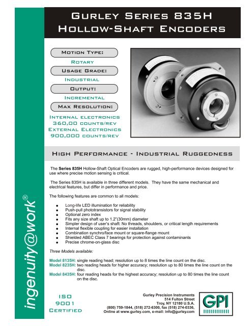
<strong>Gurley</strong> Series 835HHollow-Shaft EncodersMotion Type:RotaryUsage Grade:IndustrialOutput:IncrementalMax Resolution:Internal electronics360,00 counts/revExternal Electronics900,000 counts/revHigh Performance - Industrial RuggednessThe Series 835H Hollow-Shaft Optical Encoders are rugged, high-performance devices designed foruse where precise motion sens<strong>ing</strong> is critical.The Series 835H is available in three different models. They have the same mechanical andelectrical features, but differ in performance and price.<strong>ing</strong>e<strong>nuity@</strong>wo<strong>rk</strong>The follow<strong>ing</strong> features are common to all models: Long-life LED illumination for reliability Push-pull phototransistors for signal stability Optional zero index Fits any size shaft up to 1.2”(30mm) diameter Simpler design of user’s shaft: No threads, shoulders, or critical length requirements Internal flexible coupl<strong>ing</strong> for easier installation Combination synchro/face mount or square-flange mount Shielded ABEC Class 7 bear<strong>ing</strong>s for protection against contaminants Precise chrome-on-glass discThree Models available:Model 8135H: s<strong>ing</strong>le read<strong>ing</strong> head; resolution up to 8 times the line count on the disc.Model 8235H: two read<strong>ing</strong> heads for higher accuracy; resolution up to 80 times the line count on thedisc.Model 8435H: four read<strong>ing</strong> heads for the highest accuracy; resolution up to 80 times the line counton the disc.ISO9001Certified<strong>Gurley</strong> <strong>Precision</strong> <strong>Instruments</strong>514 Fulton StreetTroy, NY 12180 U.S.A.(800) 759-1844, (518) 272-6300, fax (518) 274-0336,Online at www.gurley.com, e-mail: info@gurley.comGPIIIIIIIIIIIIIII
SPECIFICATIONSSEENOTEMODEL8135HMODEL8235HMODEL8435HMaximum line count on disc11,250Max cycles/rev with internal electronics22,500 56,250 90,000Max counts/rev (after quad edge detection)90,000225,000360,000Max cycles/rev with external electronics5N/A225,000Max counts/rev with external electronics(after quad edge detection)5N/A900,000Instrument error, ± arcsec1,230155Quadrature error, ± electrical degrees1,3302415Interpolation error, ± quanta1,40.150.10 0.051x square waves5100FREQUENCYRESPONSEkHz2x square waves5x square waves8x square waves555N/AN/A150300500Up to 20x square waves5,6N/A1000Maximum weight, oz (g)25 (715)Start<strong>ing</strong> torque, in-oz (N-m) [at 20°C]2.0 (0.014)Runn<strong>ing</strong> torque, in-oz (N-m) [at 20°C]1.0 (0.007)2 2Moment of inertia, in-oz-s (g-cm )0.022 (1600)2Maximum acceleration, rad/s374 x 10Operat<strong>ing</strong> temperature range, °F (°C)41 to 158 (5 to 70)Storage temperature range, °F (°C)0 to 160 (-18 to 71)Humidity, % RH non-condens<strong>ing</strong>98Shock50 g, 11 msVibration15 g, 0-2000 HzNOTES:Maximum slew speed, rpmSee BEARING LUBRICANTS table1. Total Optical Encoder Error is the algebraic sum of Instrument Error + Quadrature Error + Interpolation Error. Typically, these errorsources sum to a value less than the theoretical maximum. Error is guaranteed at 20°C and is defined at the signal transitions. Itdoes not include quantization error, which is ±1/2 quantum. ("Quantum" is the final resolution of the encoder, after user's 1X, 2X or4X quadrature decode.)2. Instrument Error is the sum of disc pattern errors, disc eccentricity, bear<strong>ing</strong> runout and other mechanical imperfections within theencoder. This error tends to vary slowly around a revolution.3. Quadrature Error is the combined effect of phas<strong>ing</strong> and duty cycle tolerances and other variables in the basic analog signals. Thiserror applies to data taken at all four transitions within a cycle; if data are extracted from 1X square waves on a 1X basis (i.e., atonly one transition per cycle), this error can be ignored.Error in arcseconds = (3600) x (error in electrical degrees) / (disc line count)4. Interpolation Error is present only when the resolution has been electronically increased to more than four data points per opticalcycle. It is the sum of all the tolerances in the electronic interpolation circuitry.Error in arcseconds = (1296000) x (error in quanta) / (counts/rev)5. See BEARING LUBRICANTS table6. With external Model HR2A High Resolution Electronics. Frequency response is as stated for output signals, or 50 kHz at the disc,whichever is limit<strong>ing</strong>.As part of our continu<strong>ing</strong> product improvement program, all specifications are subject to change wit ho ut n ot ic e.835HPage 2 of 6V3.1<strong>Gurley</strong> <strong>Precision</strong> <strong>Instruments</strong>514 Fulton StreetTroy, NY 12180 U.S.A.(800) 759-1844, (518) 272-6300, fax (518) 274-0336,Online at www.gurley.com, e-mail: info@gurley.comGPIIIIIIIIIIIIIII
EXTENDED RESOLUTIONWith internal electronics, the Series 835H generatesresolution up to 360,000 counts/rev (3.6 arcsec/count)after 4X quadrature decode. For finer resolution (up to900,000 counts/rev, or 1.44 arcsec/count), the HR2Aexternal electronics package offeres any number ofquadrature square waves from 1 to 20 times the line counton the disc, or fixed-duration pulses at 1, 2 or 4 times anyinteger from 1 to 20. Please refer to the HR2A sheet forfull details.INTERNAL COUPLINGA flexible metal bellows and clamp<strong>ing</strong> r<strong>ing</strong> form anaccurate coupl<strong>ing</strong> that absorbs normal installationmisalignments and prevents damage to the encoderbear<strong>ing</strong>s. Keep<strong>ing</strong> the misalignments within the follow<strong>ing</strong>constraints will assure infinite life of the coupl<strong>ing</strong>, but willintroduce some error. To preserve the encoder’saccuracy, misalignments should be kept as small aspossible.100P + 14E + 0.125A < 0.5Where:P = Parallel offset, inches (0.005 max)E = Axial Extension or Compression,inches (0.035 max)A = Angular Misalignment, degrees(4° max)Parallel offset, P, is equal to the total offsetbetween the centerline of the encoder and thecenterline of the user's shaft, plus half the radialrunout of the user's shaft (TIR/2).MAXIMUM COUPLING DEFLECTIONS-3Parallel Offset (P), inches x 1054321 110 20 30Axial Extension or Compression (E), inches x 10Shaft Dia., Inches1.2501.1501.00023* with zero offsetAngular MisalignmentA = 0INTERFERENCE CONSTRAINTSFOR LARGE SHAFTSPage 3 of 6V3.1Max. Angular Mis-Alignment, Degrees0.25*1.63.2835H-3SpecificationsSquareWaveOutput(outputcodesL,C,T,F)BufferedSinusoidOutput(outputcode B)PulseOutput(outputcode P)OUTPUT PIN CONNECTIONSCONN. CODE P Q SCONN. TYPE: NONE DA-15P DE-9PFUNCTION: COLOR PIN # PIN #A(1)/AB(1)/BIND(1)/IND+VCOMMCASESHIELDSINCOSIND+VCOMMCASESHIELDCW/CWCCW/CCWIND/IND+VCOMMCASESHIELDYellowBrownGreenOrangeBlueWhiteRedBlackGray(2)BareYellowGreenBlueRedBlackGray(2)BareYellowBrownGreenOrangeBlueWhiteRedBlackGray(2)Bare87542110139149115415885487211013914MATING CONN. - M01 M061. Available with RS-422 Differential Line Driver Output (code L) only.2. The shield is not connected to the case of the encoder.3. Channel B (cos) leads Channel A (sin ) for CW shaft rotation, look<strong>ing</strong> at the mount<strong>ing</strong> face.<strong>Gurley</strong> <strong>Precision</strong> <strong>Instruments</strong>514 Fulton StreetTroy, NY 12180 U.S.A.(800) 759-1844, (518) 272-6300, fax (518) 274-0336,Online at www.gurley.com, e-mail: info@gurley.com48372659113748265911GPIIIIIIIIIIIIIII
DimensionsCLAMP ADAPTERRING.46 [11.7] MAX(ROTATING SEAL)-X-.0251.935[49.15 .64].100 [2.5]8-32 UNC-2BX .25 DP4 PLCS EQ SP ON A2.690 [68.33] B.C.SEE DIAMETERCODE TABLE.38 [9.7]3.54[89.9]MAXø2.44 [62.0]WITH SEALø1.85 [47.0]NO SEAL.40 [10.2] MAX(NO SEAL)+.0000 ø3.625-.0005 [92.08]3.3750+0[ø85.7 ] -.013+.013.48-.00[88.4]1.26 THRU+.3[ø32.0 -0](TO CLAMPADAPTER RING).42[10.7].093 [2.36]+.010.093 -.005+.25[2.36 -.13]SYNCHRO/FACE MOUNTBASE CODE A, B OR ESEE NOTE 12230'NOTES:1. SEE BEARING LUBRICANTS TABLE.2. ALL DIMENSIONS IN INCHES [mm].0.2[5] SHIELDED CABLE10 CONDUCTOR (5 TWISTED PAIRS)28 AWG (7/36), PVC JACKETSTANDARD LENGTH = 18[457]CONNECTOR CODE P = PIGTAILSQ = DA-15PS = DE-9P+.000-.0013.345+0[84.96-.03]2.17 [55.1] R TYP.177 THRU 4 HOLESEQ SP ON A3.937 [100.00] B.C.45.023.62.5 [92.0 ]SQUARE.318 [8.08].100 [2.5]SQUARE FLANGE MOUNTBASE CODE C, D OR FSEE NOTE 1SEALSWhen ordered with optional shaft seals, the encoder has a magnetic-liquid seal at the base end and a V-r<strong>ing</strong> seal at theclamp end. The magnetic liquid seal consists of an oil film with suspended magnetic particles. The medium, which is held inplace magnetically, forms an effective seal against airborne particulates. The nitrile rubber V-r<strong>ing</strong> seal comprises a flexiblelip attached to the seal body with an integral resilient "h<strong>ing</strong>e". It rotates with the shaft and seals axially against a stationarysurface. The flexible lip and h<strong>ing</strong>e provide effective seal<strong>ing</strong> even with end play or shaft misalignment. With seals, themaximum recommended shaft speed is 4400 rpm.BEARING LUBRICANTSThere are two standard bear<strong>ing</strong> lubricants. Andok C is specificallydesigned for severe service, high speed, long life, low torque and lowtemperature rise, and is suitable for most applications. Braycote 601is a low vapor pressure lubricant which is suitable for vacuum andclean room applications at the expense of reduced speed and servicelife and slightly higher torque.Base CodeABCDEFMount<strong>ing</strong>Synchro/faceSynchro/faceSquare flangeSquare flangeSynchro/faceSquare flangeBear<strong>ing</strong>s which are subjected to oscillatory motion, i.e., partialrevolutions and frequent reversals, or very low speed operation (
ORDERING INFORMATIONMODEL LINES IND V OUT INTERP BASE CAB CONN DIA SPECTMODEL8135H Standard accuracy8235H High accuracy8435H Highest AccuracyLINES - Disc line count00360 00500 00512 00600 0090001000 01024 01575 01800 0200002048 02500 02540 02700 0300003175 03300 03600 04000 0405004096 04200 04302 04310 0450005000 05400 06000 06400 0648007000 07200 07640 08000 0819209000 09550 09900 10000 1080011250Consult factory for other line countsIND - Index formatF Full cycle ungated (INTERP = 01)H Half cycle gated (INTERP = 02, 05)Q Quarter cycle gated (INTERP = 08)P Pulse index (OUT = P)N NoneV - Input voltage5 5 volts dcR 7-15 volts dc (OUT = F, L or P)OUT output formatB Buffered sinusoids (INTERP = 01)C Open collector (s<strong>ing</strong>le-ended sq. Waves)(INTERP = 01)F Power Buffer (s<strong>ing</strong>le-ended sq. waves)(INTERP = 01, 02)L RS-422 differential line driver(INTERP = 01, 02, 05, 08)T S<strong>ing</strong>le-ended TTL (INTERP = 01, 02)P Pulses (cw and ccw)(INTERP = 01, 02, 04, 05, 08, 10, 20)INTERP - Interpolation factor01 With buff. sinusoid output01, 02, 05, 08 With square wave output01, 02, 04, 05, 08, 10, 20 With pulse outputBASE - Base typeA Synchro/face mount, no shaft seals, AndokB Synchro/face mount, with shaft seals, AndokC Square flange mount, no shaft seals, AndokD Square flange mount, with shaft seals, AndokE Synchro/face mount, no seals, BraycoteF Synchro flange mount, no seals, BraycoteCAB - Cable length, inches (04-99)18 StandardCONN - ConnectorP Pigtails (no connector)Q DA-15PS DE-9PDIA - Shaft DiameterCODE Nominal CODE NominalShaft Dia.Shaft Dia.20E* 1.250” 06E 0.375”18E 1.125” 05E 0.3125”16E 1.000” 04E 0.250”14E 0.875” 30M 30.00mm12E 0.750” 25M 25.00mm10E 0.625” 20M 20.00mm08E 0.500” 10M 10.00mm* Not recommended - consult factorySPEC - Special codeX To define non-standard featuresN No special featuresAccessories (order separately)AX06399 Synchro cleats (see separate data sheet)M01 Mat<strong>ing</strong> connector for DA-15PM06 Mat<strong>ing</strong> connector for DE-9PISC3NÒInterface card for IBM PCSPECIAL CAPABILITIESFor special situations, we can optimize catalog encoders to provide higher frequency response, greater accuracy, wider temperaturerange, reduced torque, non-standard line counts, or other modified parameters. In addition, we regularly design and manufacturecustom encoders for user-specific requirements. These range from high-volume, low-cost, limited-performance commercialapplications to encoders for military, aerospace and similar high-performance, high-reliability conditions. We would welcome theopportunity to help you with your encoder needs.WARRANTY<strong>Gurley</strong> <strong>Precision</strong> <strong>Instruments</strong> offers a limited warranty against defects in material and wo<strong>rk</strong>manship for a period of one year from thedate of shipment.835HPage 6 of 6V3.1<strong>Gurley</strong> <strong>Precision</strong> <strong>Instruments</strong>514 Fulton StreetTroy, NY 12180 U.S.A.(800) 759-1844, (518) 272-6300, fax (518) 274-0336,Online at www.gurley.com, e-mail: info@gurley.comGPIIIIIIIIIIIIIII