02024 Components Specifier's Guide - Isiesa
02024 Components Specifier's Guide - Isiesa
02024 Components Specifier's Guide - Isiesa
- No tags were found...

You also want an ePaper? Increase the reach of your titles
YUMPU automatically turns print PDFs into web optimized ePapers that Google loves.
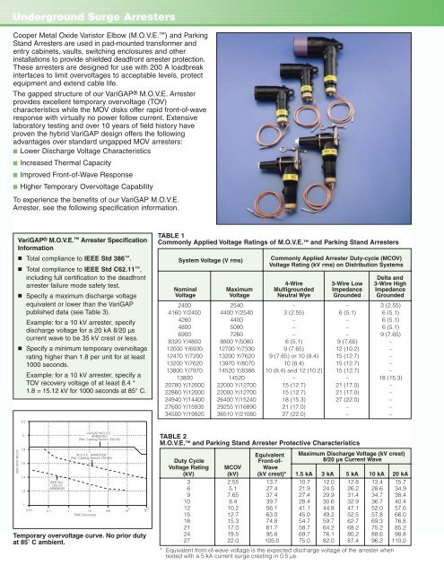
Underground Surge ArrestersCooper Metal Oxide Varistor Elbow (M.O.V.E. ) and ParkingStand Arresters are used in pad-mounted transformer andentry cabinets, vaults, switching enclosures and otherinstallations to provide shielded deadfront arrester protection.These arresters are designed for use with 200 A loadbreakinterfaces to limit overvoltages to acceptable levels, protectequipment and extend cable life.The gapped structure of our VariGAP ® M.O.V.E. Arresterprovides excellent temporary overvoltage (TOV)characteristics while the MOV disks offer rapid front-of-waveresponse with virtually no power follow current. Extensivelaboratory testing and over 10 years of field history haveproven the hybrid VariGAP design offers the followingadvantages over standard ungapped MOV arresters:■ Lower Discharge Voltage Characteristics■ Increased Thermal Capacity■ Improved Front-of-Wave Response■ Higher Temporary Overvoltage CapabilityTo experience the benefits of our VariGAP M.O.V.E.Arrester, see the following specification information.VariGAP ® M.O.V.E. Arrester SpecificationInformation■ Total compliance to IEEE Std 386 .■ Total compliance to IEEE Std C62.11 ,including full certification to the deadfrontarrester failure mode safety test.■■Specify a maximum discharge voltageequivalent or lower than the VariGAPpublished data (see Table 3).Example: for a 10 kV arrester, specifydischarge voltage for a 20 kA 8/20 µscurrent wave to be 35 kV crest or less.Specify a minimum temporary overvoltagerating higher than 1.8 per unit for at least1000 seconds.Example: for a 10 kV arrester, specify aTOV recovery voltage of at least 8.4 *1.8 = 15.12 kV for 1000 seconds at 85° C.2.2TABLE 1Commonly Applied Voltage Ratings of M.O.V.E. and Parking Stand ArrestersSystem Voltage (V rms)Commonly Applied Arrester Duty-cycle (MCOV)Voltage Rating (kV rms) on Distribution SystemsDelta and4-Wire 3-Wire Low 3-Wire HighNominal Maximum Multigrounded Impedance ImpedanceVoltage Voltage Neutral Wye Grounded Grounded2400 2540 – – 3 (2.55)4160 Y/2400 4400 Y/2540 3 (2.55) 6 (5.1) 6 (5.1)4260 4400 – – 6 (5.1)4800 5080 – – 6 (5.1)6900 7260 – – 9 (7.65)8320 Y/4800 8800 Y/5080 6 (5.1) 9 (7.65) –12000 Y/6930 12700 Y/7330 9 (7.65) 12 (10.2) –12470 Y/7200 13200 Y/7620 9 (7.65) or 10 (8.4) 15 (12.7) –13200 Y/7620 13970 Y/8070 10 (8.4) 15 (12.7) –13800 Y/7970 14520 Y/8388 10 (8.4) and 12 (10.2) 15 (12.7) –13800 14520 – – 18 (15.3)20780 Y/12000 22000 Y/12700 15 (12.7) 21 (17.0) –22860 Y/12000 22000 Y/12700 15 (12.7) 21 (17.0) –24940 Y/14400 26400 Y/15240 18 (15.3) 27 (22.0) –27600 Y/15935 29255 Y/16890 21 (17.0) – –34500 Y/19920 36510 Y/21080 27 (22.0) – –PER UNIT MCOV21.81.61.41.210.01IEEE Std.C62.22MINIMUMVariGAP M.O.V.E.ARRESTER(Ref. Catalog Section 235-55)TABLE 2M.O.V.E. and Parking Stand Arrester Protective CharacteristicsM.O.V.E. ARRESTER(Ref. Catalog Section 235-65)0.1 110 100 10 3 10TIME (Seconds)Temporary overvoltage curve. No prior dutyat 85˚ C ambient.Equivalent Maximum Discharge Voltage (kV crest)Duty Cycle Front-of- 8/20 µs Current WaveVoltage Rating MCOV Wave(kV) (kV) (kV crest)* 1.5 kA 3 kA 5 kA 10 kA 20 kA3 2.55 13.7 10.7 12.0 12.8 13.4 15.76 5.1 27.4 21.9 24.5 26.2 28.6 34.99 7.65 37.4 27.4 29.9 31.4 34.7 38.410 8.4 39.7 28.4 30.6 32.9 36.7 40.412 10.2 56.1 41.1 44.8 47.1 52.0 57.615 12.7 63.0 45.0 49.2 52.5 57.8 66.018 15.3 74.8 54.7 59.7 62.7 69.3 76.821 17.0 81.7 58.7 64.2 68.2 75.2 85.224 19.5 95.8 69.7 76.1 80.2 88.6 98.827 22.0 105.0 75.0 82.0 87.4 96.2 110.0* Equivalent front-of-wave voltage is the expected discharge voltage of the arrester whentested with a 5 kA current surge cresting in 0.5 µs.