02024 Components Specifier's Guide - Isiesa
02024 Components Specifier's Guide - Isiesa
02024 Components Specifier's Guide - Isiesa
- No tags were found...

Create successful ePaper yourself
Turn your PDF publications into a flip-book with our unique Google optimized e-Paper software.
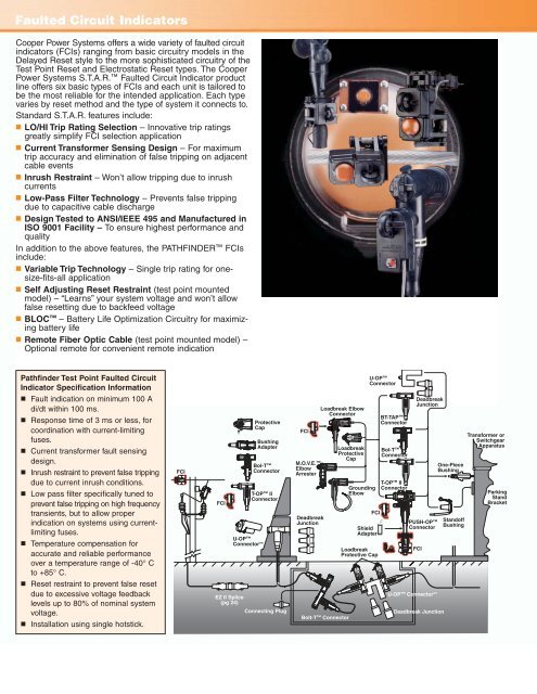
Faulted Circuit IndicatorsCooper Power Systems offers a wide variety of faulted circuitindicators (FCIs) ranging from basic circuitry models in theDelayed Reset style to the more sophisticated circuitry of theTest Point Reset and Electrostatic Reset types. The CooperPower Systems S.T.A.R. Faulted Circuit Indicator productline offers six basic types of FCIs and each unit is tailored tobe the most reliable for the intended application. Each typevaries by reset method and the type of system it connects to.Standard S.T.A.R. features include:■ LO/HI Trip Rating Selection – Innovative trip ratingsgreatly simplify FCI selection application■ Current Transformer Sensing Design – For maximumtrip accuracy and elimination of false tripping on adjacentcable events■ Inrush Restraint – Won’t allow tripping due to inrushcurrents■ Low-Pass Filter Technology – Prevents false trippingdue to capacitive cable discharge■ Design Tested to ANSI/IEEE 495 and Manufactured inISO 9001 Facility – To ensure highest performance andqualityIn addition to the above features, the PATHFINDER FCIsinclude:■ Variable Trip Technology – Single trip rating for onesize-fits-allapplication■ Self Adjusting Reset Restraint (test point mountedmodel) – “Learns” your system voltage and won’t allowfalse resetting due to backfeed voltage■ BLOC – Battery Life Optimization Circuitry for maximizingbattery life■ Remote Fiber Optic Cable (test point mounted model) –Optional remote for convenient remote indicationPathfinder Test Point Faulted CircuitIndicator Specification InformationU-OPConnector■■■■■■Fault indication on minimum 100 Adi/dt within 100 ms.Response time of 3 ms or less, forcoordination with current-limitingfuses.Current transformer fault sensingdesign.Inrush restraint to prevent false trippingdue to current inrush conditions.Low pass filter specifically tuned toprevent false tripping on high frequencytransients, but to allow properindication on systems using currentlimitingfuses.Temperature compensation foraccurate and reliable performanceover a temperature range of -40° Cto +85° C.FCIFCIU-OPConnector**ProtectiveCapBushingAdapterBol-TConnectorT-OP IIConnectorFCIM.O.V.E.ElbowArresterDeadbreakJunctionLoadbreak ElbowConnectorLoadbreakProtectiveCapGroundingElbowFCIShieldAdapterLoadbreakProtective CapBT-TAPConnectorBol-TConnectorT-OP IIConnectorDeadbreakJunctionPUSH-OPConnectorFCIOne-PieceBushingStandoffBushingTransformer orSwitchgearApparatusParkingStandBracket■ Reset restraint to prevent false resetdue to excessive voltage feedbacklevels up to 80% of nominal systemvoltage.■ Installation using single hotstick.EZ II Splice(pg 24)Connecting PlugBolt-T ConnectorU-OP Connector**Deadbreak Junction