02024 Components Specifier's Guide - Isiesa
02024 Components Specifier's Guide - Isiesa
02024 Components Specifier's Guide - Isiesa
- No tags were found...

Create successful ePaper yourself
Turn your PDF publications into a flip-book with our unique Google optimized e-Paper software.
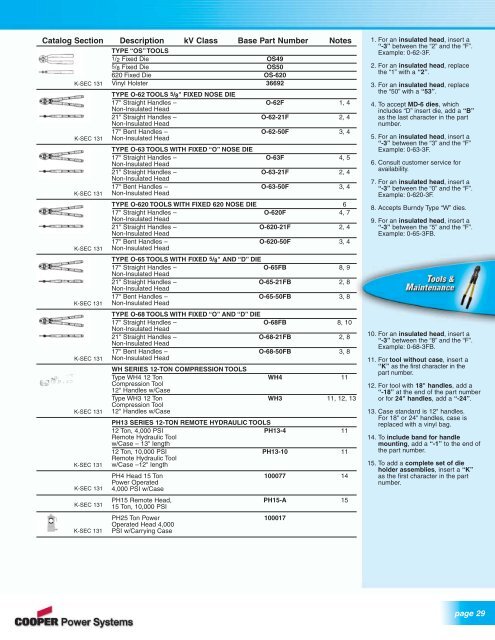
Catalog Section Description kV Class Base Part Number NotesTYPE “OS” TOOLS1/ 2 Fixed Die OS495/ 8 Fixed Die OS50620 Fixed Die OS-620Vinyl Holster 36692K-SEC 131K-SEC 131K-SEC 131K-SEC 131K-SEC 131K-SEC 131K-SEC 131K-SEC 131K-SEC 131K-SEC 131K-SEC 131TYPE O-62 TOOLS 5/ 8" FIXED NOSE DIE17" Straight Handles – O-62F 1, 4Non-Insulated Head21" Straight Handles – O-62-21F 2, 4Non-Insulated Head17" Bent Handles – O-62-50F 3, 4Non-Insulated HeadTYPE O-63 TOOLS WITH FIXED “O” NOSE DIE17" Straight Handles – O-63F 4, 5Non-Insulated Head21" Straight Handles – O-63-21F 2, 4Non-Insulated Head17" Bent Handles – O-63-50F 3, 4Non-Insulated HeadTYPE O-620 TOOLS WITH FIXED 620 NOSE DIE 617" Straight Handles – O-620F 4, 7Non-Insulated Head21" Straight Handles – O-620-21F 2, 4Non-Insulated Head17" Bent Handles – O-620-50F 3, 4Non-Insulated HeadTYPE O-65 TOOLS WITH FIXED 5/ 8" AND “D” DIE17" Straight Handles – O-65FB 8, 9Non-Insulated Head21" Straight Handles – O-65-21FB 2, 8Non-Insulated Head17" Bent Handles – O-65-50FB 3, 8Non-Insulated HeadTYPE O-68 TOOLS WITH FIXED “O” AND “D” DIE17" Straight Handles – O-68FB 8, 10Non-Insulated Head21" Straight Handles – O-68-21FB 2, 8Non-Insulated Head17" Bent Handles – O-68-50FB 3, 8Non-Insulated HeadWH SERIES 12-TON COMPRESSION TOOLSType WH4 12 Ton WH4 11Compression Tool12" Handles w/CaseType WH3 12 Ton WH3 11, 12, 13Compression Tool12" Handles w/CasePH13 SERIES 12-TON REMOTE HYDRAULIC TOOLS12 Ton, 4,000 PSI PH13-4 11Remote Hydraulic Toolw/Case – 13" length12 Ton, 10,000 PSI PH13-10 11Remote Hydraulic Toolw/Case –12" lengthPH4 Head 15 Ton 100077 14Power Operated4,000 PSI w/CasePH15 Remote Head, PH15-A 1515 Ton, 10,000 PSIPH25 Ton Power 100017Operated Head 4,000PSI w/Carrying Case1. For an insulated head, insert a“-3” between the “2” and the “F”.Example: 0-62-3F.2. For an insulated head, replacethe “1” with a “2”.3. For an insulated head, replacethe “50” with a “53”.4. To accept MD-6 dies, whichincludes “D” insert die, add a “B”as the last character in the partnumber.5. For an insulated head, insert a“-3” between the “3” and the “F”Example: 0-63-3F.6. Consult customer service foravailability.7. For an insulated head, insert a“-3” between the “0” and the “F”.Example: 0-620-3F.8. Accepts Burndy Type “W” dies.9. For an insulated head, insert a“-3” between the “5” and the “F”.Example: 0-65-3FB.10. For an insulated head, insert a“-3” between the “8” and the “F”.Example: 0-68-3FB.11. For tool without case, insert a“K” as the first character in thepart number.12. For tool with 18" handles, add a“-18” at the end of the part numberor for 24" handles, add a “-24”.13. Case standard is 12" handles.For 18" or 24" handles, case isreplaced with a vinyl bag.14. To include band for handlemounting, add a “-1” to the end ofthe part number.15. To add a complete set of dieholder assemblies, insert a “K”as the first character in the partnumber.page 29