PRECISION INSTRUMENTS for MEASUREMENT and ... - meatest.cz
PRECISION INSTRUMENTS for MEASUREMENT and ... - meatest.cz
PRECISION INSTRUMENTS for MEASUREMENT and ... - meatest.cz

You also want an ePaper? Increase the reach of your titles
YUMPU automatically turns print PDFs into web optimized ePapers that Google loves.
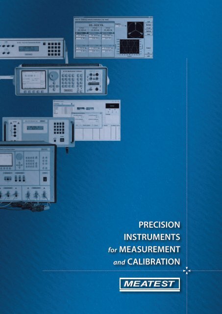
<strong>PRECISION</strong><strong>INSTRUMENTS</strong><strong>for</strong> <strong>MEASUREMENT</strong><strong>and</strong> CALIBRATION
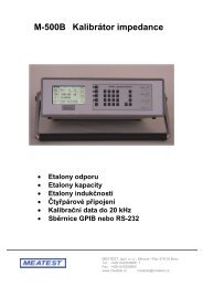
Production lineMultifunction CalibratorsSoftware <strong>for</strong> automatic CalibrationCamera ModuleOne-phase <strong>and</strong> Three-phase Power/Energy CalibratorHigh Current AC/DC CalibratorImpedance CalibratorResistance <strong>and</strong> Capacitance Programmable BoxesRTD Temperature Sensor SimulatorResistance St<strong>and</strong>ardsTemperature/Humidity MeterPrecision Oil BathElectromagnetic FlowmetersCompany profileCzech company MEATEST was found in 1991. Profile of company includes development,manufacturing <strong>and</strong> sale of instruments especially <strong>for</strong> use in calibration laboratories <strong>and</strong> <strong>for</strong> accuratemeasuring in industry. MEATEST is member of national metrology association Czech calibrationassociation, Czech metrology association <strong>and</strong> Calibration association of Slovak republic.ProductionMultifunction <strong>and</strong> process calibrators, st<strong>and</strong>ards, instruments <strong>for</strong> metrology of electric quantities.Software <strong>and</strong> hardware accessories <strong>for</strong> computer-based automatic calibrations.Special instruments <strong>for</strong> metrology like Temperature oil bathes, Programmable resistance decades etc.Electromagnetic flowmeters <strong>for</strong> industrial application.Quality management system & TraceabilityMEATEST quality management system is certified according to st<strong>and</strong>ard ISO 9001:2000.All main processes manufacturing, development, sale, services <strong>and</strong> calibrations are certified<strong>and</strong> every year audited by Bureau Veritas Certification.MEATEST main st<strong>and</strong>ards are traceable directly to the Czech national st<strong>and</strong>ards in Czech MetrologyInstitute (CMI). CMI laboratories are accredited by Czech institute <strong>for</strong> accreditation, a member ofEuropean co-operation <strong>for</strong> accreditation.1
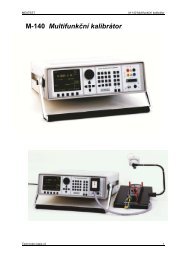
M-140 / M-142 Multifunction Calibrator SeriesM-140M-142••••••••AC/DC voltage/current to 1000V/30ABest accuracy 15ppm in DCV modeAC/DC Power/Energy, Phase shiftResistance, Capacitance, Frequency••••••Build-in DC multimeter withVoltage/Current/Resistance/FrequencyTC/RTD Temperature Sensor SimulationGPIB <strong>and</strong> RS-232 as st<strong>and</strong>ardM-140/142 series represents category of multifunction calibrators of electric quantities <strong>for</strong> general application. Various versions offerdifferent range of electric functions, accuracies <strong>and</strong> user com<strong>for</strong>tability. Build-in multimeter enables complex testing <strong>and</strong> calibrating ofsources <strong>and</strong> meters of electric quantities. Multimeters, scopes, power meters, etc. can be directly calibrated with the instrument in sourcingmode. In measuring mode, the calibrator can be used <strong>for</strong> testing of DC voltage/current sources, <strong>for</strong> temperature measurements <strong>and</strong> <strong>for</strong>measuring other non-electric quantities through external sensors. Simultaneous generation <strong>and</strong> measurement allows calibration, adjusting<strong>and</strong> testing of various types of regulators, panel-meters, converters, indicators etc.Either manual control from the front panel keyboard, or remote control via GPIB bus or via RS-232 is available.ModelDCVaccuracyDCV ACVDCI ACIShapewave<strong>for</strong>mPowerEnergyRTDsimulationTCsimulation Resistance Capacitance Frequency Built-inmultimeterM-140 35 ppm 1 000 V 20 A Y Y Y Y 50 MΩ 50 μF 20 MHz YM-142 15 ppm 1 000 V 30 A Y Y Y Y 1 000 MΩ 100 μF 20 MHz YInterfaceGPIBRS232GPIBRS232M-140i 35 ppm 1 000 V 20 A N N N Y N N N N RS232M-142i 15 ppm 1 000 V 30 A N N N Y N N N N RS232DC Voltage Ranges & Accuracy / 1 yearRangeM-140/M-140i [ppm ofvalue + V]M-142/M-142i [ppm ofvalue + V]0 μV – 20 mV 300 + 10 μ 50 + 6 u20 mV – 200 mV 100 + 15 μ 15 + 8 u200 mV – 2 V 30 + 16 u 12 + 10 u2 V - 20 V 30 + 100 u 10 + 50 u20 V – 240 V 30 + 1 m 20 + 500 u240 V – 1000 V 50 + 50 m 50 + 20 mM-140iDC Current Ranges & Accuracy / 1 yearRangeM-140/M-140i[ppm of value + A]M-142/M-142i[ppm of value + A]0 μA – 200 μA 500 + 20 nA 500 + 20 n200 μA - 2 mA 200 + 100 nA 200 + 100 n2 mA - 20 mA 100 + 600 nA 100 + 600 n20 mA – 200 mA 100 + 6 uA 100 + 6 u200 mA – 2 A 150 + 100 uA 150 + 100 u2 A – 20 A * 1 200 + 2 mA 200 + 2 m20A – 30A * 1 — 300 + 3 m* 1 Limited time of continuous current in range 10 to 30AM-140 in 19˝ versionMEATEST, spol. s r. o., Zelezna 3, CZ - 619 00 Brno, Czech Republic | tel. +420 543 250 886, 887 | fax +420 543 250 890 | e-mail: <strong>meatest</strong>@<strong>meatest</strong>.<strong>cz</strong> | www.<strong>meatest</strong>.com, www.<strong>meatest</strong>.<strong>cz</strong>M-140, M-142/1
SpecificationAC Voltage Ranges & Accuracy / 1 yearRangeM-140/M-140i[ppm of value + V]M-142/M-142i[ppm of value + V]M-140/M-140i M-142/M-142i[ppm of value + V]M-140/M-140i M-142/M-142i[ppm of value + V]20 Hz - 10 kHz 20 Hz - 10 kHz 10 kHz - 50 kHz 50 kHz - 100 kHz1 mV - 20 mV 2 000 + 30 μ 2 000 + 30 μ 2000 + 1000 + 20 μ 1.0 + 0.10 + 20 μ20 mV - 200 mV 1 000 + 80 μ 1 000 + 80 μ 1500 + 500 + 20 μ 0.3 + 0.05 + 20 μ200 mV - 2 V 250 + 100 u 180 + 100 u 500 + 200 μ 0.2 + 1 m2 V - 20 V 250 + 1 m 180 + 1 m 500 + 6 m 0.2 + 10 m20 V – 240 V * 3 250 + 20 m 180 + 20 m — —240 V – 1000 V 300 + 200 m * 2 300 + 200 m * 2 — —* 2 valid <strong>for</strong> f < 1000 Hz; * 3 frequency in range 200 to 240 V is limited to 1 kHzAC Current Ranges & Accuracy / 1 year*RangeM-140/M-140i[ppm of value + A]M-142/M-142i[ppm of value + A]M-140/M-140i M-142/M-142i[ppm of value + A]M-140/M-140i M-142/M-142i[ppm of value + A]20 Hz – 1 kHz 20 Hz – 1 kHz 1 kHz – 5 kHz 5 kHz – 10 kHz1 μA – 200 μA 1500 + 20 n 1500 + 20 n 3000 + 220 n —200 μA – 2 mA 700 + 200 n 700 + 200 n 2000 + 1 μ 5000 + 1400 n2 mA - 20 mA 500 + 1 u 500 + 1 u 2000 + 10 μ 5000 + 14 μ20 mA – 200 mA 500 + 10 u 500 + 10 u 2000 + 100 μ 5000 + 140 μ200 mA - 2 A 500 + 100 u 500 + 100 u — —10 A – 20 A * 4 * 6 1000 + 6 m 1000 + 6 m — —20 A – 30 A * 5 — 20000 + 9 m — —4 Continuous output current maximum time is 60 sec <strong>for</strong> set value 20 A, <strong>for</strong> M-142 <strong>and</strong> 30 s <strong>for</strong> M-140.5 Continuous output current maximum time is 30 sec <strong>for</strong> set value 30 A.6 When Option 140-50 Current coil is used, add uncertainty 0.3 % of the set current to the value specified in the above table. Output current is multiplied by factor 50.Function Shape (M-140 / M-142 versions only)Range of voltage: 1 mV to 200 VRange of current: 100 µA to 2 AOutput wave<strong>for</strong>m: square, positive, negative, symmetrical, ramp A, ramp B, triangle, truncated sinusPeak value accuracy: 0.3 %Frequency (M-140 / M-142 versions only)Type Range Frequency acc. [%] Amplitude Amplitude acc. [%] Ratio [-] Ratio acc. [-]PWM (POS, NEG, SYM) 0.1 Hz–100 kHz 0.005 1 mV–10 V 0.1 0.1–0.99 0.0005HSO * 7 0.1 Hz–20 MHz 0.005 5 V pk-pk 10 — —* 7 Rise time of generated output wave<strong>for</strong>m in HSO function < 5 nsResistance (M-140 / M-142 versions only)M-140 M-142Range ppm of value + mΩ Range ppm of value + mΩ0 Ω – 100 Ω 300 + 10 0–10 Ω 300 + 5100 Ω – 400 Ω 150 10 – 33 Ω 150 + 5400 Ω – 2 kΩ 150 100 – 330 Ω 100 + 52kΩ – 10 kΩ 150 330–1 kΩ 10010 kΩ – 40 kΩ 150 1 – 3.3 kΩ 10040 kΩ – 200 kΩ 150 3.3–10 kΩ 100200kΩ – 1 MΩ 500 10 – 33 kΩ 1001 MΩ – 4 MΩ 1000 33 – 100 kΩ 1004 MΩ – 20MΩ 2000 100 – 330 kΩ 10020 MΩ – 50MΩ 5000 330 – 1 MΩ 1001 – 3.3 MΩ 2003.3–10MΩ 50010 – 33 MΩ 100033–100 MΩ 2000100 MΩ – 1 GΩ 5000Maximal compliance voltage on output terminals 5-8Vpk <strong>for</strong> model M-140<strong>and</strong> 10-20Vpk <strong>for</strong> model M-142.Capacitance (M-140 / M-142 versions only)M-140 M-142Range % of value + pF Range % of value + pF900 pF – 2.5 nF 0.5 + 15 700 pF–1 nF 0.5 + 152.5 nF – 10 nF 0.5 1 nF–3.3 nF 0.5 + 510 nF – 50 nF 0.5 3.3 nF – 10 nF 0.550 nF–250 nF 0.5 10 nF–33 nF 0.5250 nF – 1 μF 0.5 33 nF–100 nF 0.51 μF–3.5 μF 1 100 nF–330 nF 13.5 μF – 5 μF 1 330 nF – 1 μF 15 μF–10 μF 1.5 1 μF–3.3 μF 1.510 μF – 50 μF 2.0 3.3 μF–10 μF 1.510 μF – 100 μF 2.0Maximal compliance voltage on output terminals 5.5 Vpk.M-140, M-142/2
SpecificationAC/DC Power & Energy (M-140 / M-142 versions only)Function Range AccuracyDC Voltage 0.2 V–240 V 40 to 150 ppmDC Current M-140: 2 mA–10 A M-142: 2 mA to 20A 500 to 1500 ppmAC Voltage 0.2 V–240 V 300 to 1200 ppmAC Current M-140: 2 mA–10 A M-142: 2 mA to 20A 500 to 1500 ppmFrequency 20–400 Hz 50 ppmPower factor -1 to +1 0.005–0.0005Phase 0–360 ° 0.15–0.25 °Time in energy mode 10 s to 1999 s 0.1 sAccuracy of AC power depends on set value of voltage, current, phase. Best accuracy is 0.08 %.Accuracy in energy mode depends on set value of voltage, current, phase <strong>and</strong> time. Best accuracy is 0.09 %.RTD Temperature Sensor Simulation (M-140 / M-142 versions only)Type: Pt 1.385, Pt 1.392, Ni Temperature accuracy: 0.04 °C to 0.5 °CRange of R0: 20 Ω to 2 kΩ Temperature scale: ITS 90, PTS 68Range of temperature: -200 to +850 °CTC Temperature Sensor SimulationR range [°C] -50–0 0 – 400 400–1000 1000–1767accuracy [°C] 3.2 2.1 1.4 1.7S range [°C] -50–0 0 – 250 250–1400 1400–1767accuracy [°C] 2.7 2.1 1.7 2.0B range [°C] 400–800 800 – 1000 1000–1500 1500–1820accuracy [°C] 2.8 1.8 1.6 1.8J range [°C] -210 – -100 -100 – 150 150–700 700–1200accuracy [°C] 0.9 0.5 0.6 0.7T range [°C] -200 – -100 -100 – 0 0–100 100–400accuracy [°C] 0.9 0.5 0.4 0.4E range [°C] -250 – -100 -100 – 280 280–600 600–1000accuracy [°C] 1.6 0.4 0.5 0.5K range [°C] -200 – -100 -100 – 480 480–1000 1000–1372accuracy [°C] 1.0 0.6 0.7 0.8N range [°C] -200 – -100 -100 – 0 0–580 580–1300accuracy [°C] 1.2 0.7 0.6 0.8Multimeter (M-140 / M-142 versions only)*Quantity Range AccuracyDC voltage – DCV 0 to +/-12 V 0.01 % +500 μVDC voltage – mVDC 0 to +/-2 V 0.02 % +7 μVDC current 0 to +/-25 mA 0.015 % +300 nAFrequency 1 Hz to 15 kHz 0.005Resistance 0 to 2 kΩ 0.02 % + 10 mΩRTD temperature -150 to +600 °C 0.1 °CTC temperature -250 to +1820 °C 0.4 to 4 °CSGS sensors * 8depends onthe sensor0.05 % + 10 μV+sensor unc.8 M-140 model only Voltage 2 to 10 V DCInput impedancemin. 100 MΩSensitivity0.5 mV/V to 100 mV/VDisplayed unitprogrammableSorting function1 x closure, 1 x openerMax. supply current40 mAGeneral dataWarm up time: 60 min Dimensions / Weight: 450 x 480 x 150 mm / 23 kgTemperature: Storing 0 to 40 °C @ max. 80 % r.h. Power supply: 115 V/230 V–50/60 HzReference 23 °C ± 2 °C Max. power consumption: 250 VAAccessories (included)Power cord 1 pc Option 10/11 Test lead red/black 2 pcsOperation manual 1 pc Option 40 Cable adapter <strong>for</strong> internal meter (M140/142) 1 pcTest report 1 pc Option 60 Cable adapter <strong>for</strong> four-wire resistances (M140/142) 1 pcSpare fuse 2 pcs Option 70 Cable adapter <strong>for</strong> four-wire resistances (M140/142) 1 pcRS232 cable 1 pcs Option 80 Cable adapter <strong>for</strong> low voltage measurement (M142) 1 pcAvailable extra ordered options / Applied with modelOption 140-01 Cable adapter with built-in Pt temperature sensor M140/142Option 140-41 Cable adapter <strong>for</strong> simultaneous calibrationsM140Option 10 Test lead 1m red, 1000 V/30 AM140/140i/142/142iOption 11 Test lead 1m black, 1000 V/30 AM140/140i/142/142i-Option 20 Test cable BNC-BNC M140/142Option 30 Test cable BNC-Banana M140/142Option 90 Pt100 external temperature sensorM142Option 100 Terminal adapterM140/140i/142/142iOption 140-50 Current coil x25/50M140/140i/142/142iGPIB Cable 2 m M140/142WinQbase / CALIBER Application SWM140/140i/142/142iMEATEST, spol. s r. o., Zelezna 3, CZ - 619 00 Brno, Czech Republic | tel. +420 543 250 886, 887 | fax +420 543 250 890 | e-mail: <strong>meatest</strong>@<strong>meatest</strong>.<strong>cz</strong> | www.<strong>meatest</strong>.com, www.<strong>meatest</strong>.<strong>cz</strong>M-140, M-142/3
Options <strong>and</strong> AccessoriesOption 140-01 Cable Adapter <strong>for</strong> M-140 / M-142 models140-01 cable adapter is designed <strong>for</strong> easy connection of unit under test to M-140/M-142multifunction calibrator. Basic part of the adapter is metal working pad with integratedvoltage <strong>and</strong> current outputs with banana ends.The adapter is connected to the calibrator via front panel AUXILIARY connector <strong>and</strong> mainoutput etrminals. On bottom side it contains mounted Pt100 temperature sensor throughwhich ambient temperature is measured <strong>and</strong> value is applied <strong>for</strong> automatic compensationof cold junction temperature of simulated thermocouples.Application: multimeter, ammeter, voltmeter calibrationDimensions: 230mm x 75mm x 290mmWeight:1 kgConnection: safety Ø 4mm bananaOption 140-41 Cable Adapter <strong>for</strong> M-140 modelCable adapter Option 140-41 is especially suitable <strong>for</strong> process <strong>and</strong> simultaneous calibrations.It enables to apply all input <strong>and</strong> output functions of the M-140 multifunction Calibrator withoutput/input located on the AUXILIARY output connector on the calibrator front panel. Typicalapplication is calibration <strong>and</strong> testing of such meters <strong>and</strong> transducers that need simulation oftemperature sensors on the input side <strong>and</strong> measuring of output signal 20 mA/10V on the output side.When used in TESTER mode, additional relay contact of type PASS/FAIL is located on the adapter.Application:Strain gauge sensor measuringVoltage/Current/Resistance/Frequency measuringSimultaneous calibration <strong>and</strong> measurementsDimensions / Weight: 105mm x 50mm x 170 mm / 0.5 kgOption 10/11 Test CableSt<strong>and</strong>ard test cable black/red with length 1m dimensioned <strong>for</strong>signals to 1000 V <strong>and</strong> 32 AOption 20 Test CableSt<strong>and</strong>ard test cable BNC–BNC length 1 m <strong>for</strong> calibration onfrequency ranges.Option 30 Test CableSt<strong>and</strong>ard test cable BNC–2 x Banana, length 1 m, <strong>for</strong> calibrations onfrequency ranges.Option 40 Cable AdapterCable adapter CANON 25–2 x Banana.With the adapter external source ofsignal can be measured with internalbuild-in multimeter. Option 40 enablesmeasuring of DC voltage to 12 V, DCcurrent to 25 mA, frequency to 15 kHz<strong>and</strong> temperature of TC temperaturesensors.Option 60 Cable AdapterCable adapter CANON 25–4 x Banana.Four terminal resistance measurementin build-in meter is accessible with theadapter. The option enables also directmeasuring of ambient temperature viaexternal RTD temperature sensors.Option 70 AdapterCable adapter CANON 25–4 x Banana.Four-terminal output in resistance modeof M-140 is accessible with the adapter.Four-terminal output is more accuratethan front panel output, especially <strong>for</strong>low resistance values.Option 80 Cable Adapter(M142 only)Using the adapter temperature ofexternal termocouple sensors<strong>and</strong> mVDC to 2 V can be directlymeasured.Option 90 External TemperatureSensor (M142 only)Ambient temperature can be measuredwith Pt100 sensor directly.Option 100 Terminal AdapterTerminal adapter converts front panelterminal distance from 25 mm to ¾"Option 140-50 Current Coil25/50 turns current coil <strong>for</strong> calibration ofclamp ammeters. Maximal range 1000 A.M-140, M-142/4
Front/rear panelHousing holderMultifunction coloreddisplay shows:- status of the calibrator- preset <strong>and</strong> measured values- SETUP <strong>and</strong> Calibration menu- calibration data- local or remote control- accuracy of the set valueOutput terminals:- AC/DC voltage/current- AC/DC electric power/energy- Resistance/Capacitance- Sinusoidal & non-harmonic sinalsMultifunction rotary button& cursor keysLow signal optional input/output:- Cable adapters interface- 4W resistance output- built-in meter inputs- ambient temperature sensing(Opt. 140-01)Numerical keypadMultimeter on/off inputbutton with LED indicatorFrequency outputto 20 MHzSoft display keysOne-touch function buttonsOutput on/off buttonwith LED indicatorGND terminalprotection earthPower line entry module with:* 115V/230V line voltage selector* main power line fuse* power line switchRS-232 interface GPIB interface Ventilation holeVentilation holeMEATEST, spol. s r. o., Zelezna 3, CZ - 619 00 Brno, Czech Republic | tel. +420 543 250 886, 887 | fax +420 543 250 890 | e-mail: <strong>meatest</strong>@<strong>meatest</strong>.<strong>cz</strong> | www.<strong>meatest</strong>.com, www.<strong>meatest</strong>.<strong>cz</strong>M-140, M-142/5
Front panel displayCurrent time <strong>and</strong> date indicationOutupt signal wave<strong>for</strong>mOutput parameters fieldMain parameter of theoutput signalAdditional parameters ofthe output signal like:- wave<strong>for</strong>m- frequency- absoulute or relativeDeviationoutputINput090.0000 VA9.8916 mA3. 1.2011 11:51PF = +1.000 f = 60.000 HzU = 090.0000 V I = 1.000000 ALocalCA140–40Accuracy0.073%mA DCOutput ON/OFF indicationAuxiliary in<strong>for</strong>mation- grounding- local/remote control- current coil applicationCalculated accuracyMETER fieldx 10 : 10 Mode f SetupMETER selected functionValue measured byinternal meterLine with display buttondescriptionSETUP menuOutput terminalsVoltage output terminals H <strong>and</strong> L:- DC output voltage 0 to 1000 V- AC output voltage 100 uV to 1000 V- Resistance in range 0 Ohmt to 50 MOhm (1000M in M-142)- Capacitance in range 0.9 nF to 50 uF (100 uF in M-142)- AC/DC voltage in power/energy mode- Non-harmonic wave<strong>for</strong>ms (triangle, square, saw)- Square wave<strong>for</strong>m with setable duty cycle ratio from 1 % to 99 %Current output terminals +I <strong>and</strong> -I :- DC output current from 0 uV to 20 A(30 A <strong>for</strong> M-142)- AC output current 100 uA to 20 A(30 A <strong>for</strong> M-142)- AC/DC current in power/energy modeAUXILIARY connectorFrequency output:- PWM modeAC squarewave voltage with calibrated amplitude <strong>and</strong> duty cycle ratio from1 mV to 10 V in frequency range from 0.1 Hz to 100 kHz- HF modesquarewave signal with calibrated amplitude 4Vpk-pk (0dB, -10dB, -20dB, -30dB)in frequency range from 0.1 Hz to 20 MHzGND terminalconnected to protection earthM-140, M-142/6
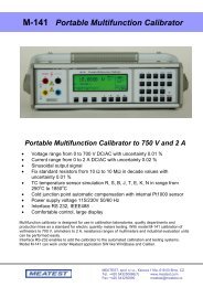
M-141 Portable Multifunction CalibratorM-141Portable multifunction calibrator is designed <strong>for</strong> use in calibrationlaboratories, quality departments <strong>and</strong> production lines as st<strong>and</strong>ard<strong>for</strong> electric quantity meters testing.Low weight <strong>and</strong> small dimensions make easy field calibrations.With model M-141 calibration of voltmeters to 750 V, ammetersto 2 A, resistance ranges of multimeters <strong>and</strong> industrial evaluationunits can be managed easily. External temperature sensor Pt1000enables accurate automatic compensation of cold junctiontemperature when TC sensor is simulated.••••••••••••••••••••AC/DC voltage to 750 V with 0.01 % accuracyAC/DC current to 2 A with 0.02 % accuracySinusoidal, square, triangle output signalsFix st<strong>and</strong>ard decimal resistorsfrom 10 Ω to 100 MΩFrequency output to 2 MHzTC temperature sensor simulation R, S, B, J, T, E,K, N in range from -250 °C to 1820 °CRTD temperature sensor simulator based onreal resistor decade (optionally)Power supply voltage 115/230V 50/60 HzInterface RS 232, IEEE488Com<strong>for</strong>table control, large displayBasic version is equipped with RS-232 interface, version M-141GPIB contains both RS232 <strong>and</strong> GPIB interfaces. Optionally, M-141Rversion is equipped with RTD simulator based on real physical resistors. Model M-141 is fully compatible to Meatest applicationSW WinQbase/CALIBER.VoltageSummary voltage range:0 µV – 750 V DC, 1 mV – 750 V ACFrequency range in AC mode: 20 Hz to 1 kHz in range 1mV to 10 V, 40 Hz to 1 kHz in range 10 V to 750 VAccuracy of frequency: 0.01%DC VoltageRange% of value + % of range0 µV – 10 mV 0.05 + 0.005 + 10 µV10 mV – 100 mV 0.01 + 0.001 + 10 µV100 mV – 1 V 0.008 + 0.0021 V – 10 V 0.008 + 0.00210 V – 100 V 0.015 + 0.004100 V – 750 V 0.018 + 0.004CurrentSummary current range:Frequency range in AC mode:AC Voltage0 µA – 2 A DC, 1 µA – 2 A AC20 Hz to 1 kHzRange % of value + % of range % of value + % z range20 Hz – 200 Hz 200 Hz – 2000 Hz1 mV – 10 mV 0.20 + 0.05 + 20 µV 0.20 + 0.10 + 20 µV10 mV – 100 mV 0.10 + 0.03 + 20 µV 0.15 + 0.05 + 20 µV100 mV – 1 V 0.05 + 0.005 0.07 + 0.011 V – 10 V 0.05 + 0.005 0.07 + 0.0310 V – 100 V * 1 0.05 + 0.010 0.07 + 0.03100 V – 750 V * 1 0.07 + 0.02 0.1 + 0.03* 1 Voltage ranges 100 <strong>and</strong> 700 V <strong>for</strong>m 40 Hz to 1000 HzDC CurrentRrange % of value + % of range0 µA – 200 µA 0.05 + 0.0 + 20 nA200 µA – 2 mA 0.025 + 0.0052 mA – 22 mA 0.015 + 0.00322 mA – 200 mA 0.015 + 0.003200 mA – 2 A 0.015 + 0.005AC CurrentRange % of value + % of range % of value + % of range20 Hz – 200 Hz 200 Hz – 1000 Hz1 µA – 200 µA 0.25 + 0.0 + 20 nA 0.30 + 0.10 + 20 nA200 µA – 2 mA 0.10 + 0.01 0.20 + 0.052 mA – 20 mA 0.07 + 0.005 0.20 + 0.0520 mA – 200 mA 0.07 + 0.005 0.20 + 0.05200 mA – 2 A 0.1 + 0.005 0.25 + 0.05Output wave<strong>for</strong>m:sinus, triangle symmetrical, triangle A/B, square, limited sin (with defined distortion k=13.45%)from 1 mV to 10 V, frequency range 20 to 80 HzMEATEST, spol. s r. o., Zelezna 3, CZ - 619 00 Brno, Czech Republic | tel. +420 543 250 886, 887 | fax +420 543 250 890 | e-mail: <strong>meatest</strong>@<strong>meatest</strong>.<strong>cz</strong> | www.<strong>meatest</strong>.com, www.<strong>meatest</strong>.<strong>cz</strong>M-141/1
TC Temperature Sensor SimulationTypes: R, S, B, J, T, E, K, NR range [°C] -50 – 0 0 – 400 400 – 1000 1000 – 1767accuracy [°C] 2.5 2.0 1.2 1.2S range [°C] -50 – 0 0 – 250 250 – 1400 1400 – 1767accuracy [°C] 2.2 2.1 1.5 1.5B range [°C] 400 – 800 800 – 1000 1000 – 1500 1500 – 1820accuracy [°C] 2.7 1.5 1.4 1.3J range [°C] -210 – -100 -100 – 150 150 – 700 700 – 1200accuracy [°C] 0.9 0.4 0.3 0.4T range [°C] -200 – -100 -100 – 0 0 – 100 100 – 400accuracy [°C] 0.9 0.5 0.3 0.3E range [°C] -250 – -100 -100 – 280 280 – 600 600 – 1000accuracy [°C] 1.7 0.3 0.2 0.3K range [°C] -200 – -100 -100 – 480 480 – 1000 1000 – 1372accuracy [°C] 0.8 0.4 0.4 0.5N range [°C] -200 – -100 -100 – 0 0 – 580 580 – 1300accuracy [°C] 1.3 0.6 0.6 0.5RTD Temperature Sensor Simulation (Option)Types: Pt, Ni Temperature scale: DIN, US/JISTemperature range Pt100-Pt200 Pt201-Pt1000-200 … 0 °C 0.2 °C 0.2 °C0 … 850 °C 0.2 °C 0.2 °CResistanceSummary range:fix decimal values 10 Ω to 100 MΩRange Accuracy [%]10 Ω 0.03 + 10 mΩ100 Ω 0.051 kΩ 0.0210 kΩ 0.02100 kΩ 0.021 MΩ 0.0510 MΩ 0.05100 MΩ 0.5Temperature range Ni100-Ni200 Ni201-Ni1000-60 … 0 °C 0.2 °C 0.1 °C0 … 300 °C 0.1 °C 0.1 °CFrequency outputWave<strong>for</strong>m: square with fix amplitude 5Vpk-pk / 50 OhmFrequency range: 0.1 Hz to 2 MHzFrequency resolution: 5 ½ digitAccuracy: 0.005 %General dataWeight:8 kgDimensions:325 mm x 111 mm x 316 mmInterface:RS232, IEEE488 (optionally)Range of working temperatures: +5 °C … +40 °CReference temperature range: 23 °C ± 2 °CPower supply voltage:115/230 V – 50/60 HzOptions (extra ordered)Option 140-50Option 10Option 11Option GPIBWinQbase/CALIBEROption 100 Terminal AdapterCurrent coil 25/50 turnsTest lead 1000 V/30 A (red)Test lead 1000 V/30 A (black)Cable GPIB IEEE488/IEEE488, 2 mApplication SW2 pcsVersionsM-141 basic model with RS232M-141GPIB RS232 <strong>and</strong> GPIB interfaceM141Rwith RTD simulator <strong>and</strong> RS232M141R GPIB with RTD simulator <strong>and</strong> GPIB/RS232Accessory (included)Power line cordOperation manualTest reportSpare fuseTest lead 1000 V/20 ATemperature sensor Pt1000RS232 Cable1 pc1 pc1 pc1 pc2 pcs1 pc1 psM-141M141 is the sipmliest but powerful calibrator<strong>for</strong> calibration of meters of electric quantities.M-141/2
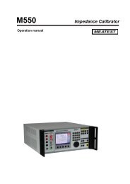
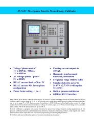
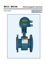
M133Electric Power / Energy CalibratorsM133 / M133iSingle phase calibratorsModels & FeaturesBoth models•• AC voltage 1 … 600 V•• DC voltage 1 … 280 V•• AC/DC current 8 mA … 30 A•• Frequency DC, 15 … 1000 Hz•• Phase 0 … 360°•• AC power 0 … 18 kVA•• DC power 0 … 8.4 kW•• AC/DC energy•• Built in process multimeter•• RS232, IEEE488 (SCPI), Ethernet•• Can be extended up to 3 phase systemM133 only•• Harmonic / interharmonic distortion•• Modulation <strong>and</strong> flicker•• Dip/SwellM133C / M133Ci Three phase calibrators Both models•• AC voltage 1 … 600V•• DC voltage 1 … 280V•• AC/DC current 8mA … 30A(90A single phase)•• Current outputs floating up to 450Vpk•• Frequency DC, 15 … 1000Hz•• Phase 0 … 360°•• AC power 0 … 54kVA•• DC power 0 … 25.2kW•• AC/DC energy•• Built in process multimeter•• RS232, IEEE488 (SCPI), EthernetM133C only•• Harmonic / interharmonic distortion•• Modulation <strong>and</strong> flicker•• Dip/SwellMEATEST, spol. s r. o., Ksirova 118A / Zelezna 3, CZ - 619 00 Brno, Czech Republic | tel. +420 543 250 886, 887 | fax +420 543 250 890 | e-mail: <strong>meatest</strong>@<strong>meatest</strong>.<strong>cz</strong> | www.<strong>meatest</strong>.com, www.<strong>meatest</strong>.<strong>cz</strong>M133/1
Basic feature of the device is precise simulation of DC <strong>and</strong> AC electric power <strong>and</strong> energy in voltage range to 280Vdc (600Vac) <strong>and</strong> in currentrange to 30 A. In AC electric power mode phase shift between voltage <strong>and</strong> current channel can be set in range 0º to 360º.Best accuracy of simulation is 0.02°. Calibrator offers high burden current of voltage output of several hundreds mA <strong>and</strong> compliance voltageof current output up to 5Vrms. Current range can be extended using Option 140-50 50 turns current coil up to 1500 A.M133 <strong>and</strong> M133C calibrators are equipped with special functions <strong>for</strong> power line voltage analyzers testing (qualimeters). It can generatecalibrated harmonic <strong>and</strong> interharmonic distortion, fluctuation harmonics, flickers, ramp signals, dips, swells <strong>and</strong> others. User interface offerssimple <strong>and</strong> user convenient programming of output signal parameters.M133i <strong>and</strong> M133Ci calibrators are delivered without the option of harmonic/interharmonic functions.SpecificationDC/AC voltage sinusVoltage range:1 Vdc to 280 Vdc, 1 Vac to 600 VacResolution:5½ dig.Frequency range: DC, 15 Hz to 1000 Hz.Synchronization to mains frequencyor external signal is available.Frequency accuracy: 0.005 %Frequency resolution: 0.001 Hz bellow 500 Hz, 0.01 Hzabove 500 HzDistortion of output signal: < 0.05 %Range% of value+ % of rangeMax. burden(mA)% of value+ % of rangeMax. burden(mA)% of value+ % of rangeMax. burden *(mA)DCDC15 – 40 Hz15 – 40 Hz70 – 1000 Hz70 – 1000 Hz40 – 70 Hz 40 – 70 Hz1.0000 – 10.0000 V 0.015 + 0.01 100 0.02 + 0.01 100 0.015 + 0.01 10010.0001 – 30.0000 V 0.015 + 0.01 200 0.02 + 0.01 200 0.015 + 0.01 20030.001 – 70.000 V 0.015 + 0.01 200 0.02 + 0.01 200 0.015 + 0.01 30070.001 – 140.000 V 0.015 + 0.01 200 0.02 + 0.01 200 0.015 + 0.01 300140.001 – 280.000 V 0.015 + 0.01 150 0.02 + 0.01 150 0.015 + 0.01 200280.001 – 600.000 V** — — 0.03 + 0.01 50 0.02 + 0.01 60* Sum of all currents (three phases) <strong>for</strong> M133C (M133Ci) is limited to 400 mA** Only fundamental harmonic in range over 280 Vac, frequency range 20 – 1000 HzDC/AC current sinusCurrent range:0.008 A to 30 AResolution:5½ dig.Frequency range: DC, 15 Hz to 1000 Hz.Synchronization to mains frequencyor external signal is available.Frequency accuracy: 0.005 %Frequency resolution: 0.001 Hz bellow 500 Hz, 0.01 Hzabove 500 HzDistortion of output signal: < 0.1 %Range% of value+ % of rangeDCMax. voltage(V)Additional uncertainty with applied current coil Opt.140-50 is 0.3 %. Output current is multiplied by factor 50.DC% of value+ % of range15 – 40 Hz70 – 1000 Hz% of value+ % of rangeMax. voltage(V)Max. voltage(V)40 – 70 Hz 15 – 400 Hz 400 – 1000 Hz0.008000 – 0.300000 A 0.025 + 0.01 8 0.03 + 0.02 0.025 + 0.01 5.5 3.50.30001 – 1.00000 A 0.025 + 0.01 8 0.03 + 0.02 0.025 + 0.01 5.5 3.51.00001 – 2.00000 A 0.025 + 0.01 8 0.03 + 0.02 0.025 + 0.01 5.5 3.52.00001 – 5.00000 A 0.025 + 0.01 5 0.03 + 0.02 0.025 + 0.01 3.5 3.55.0001 – 10.0000 A 0.03 + 0.015 5 0.04 + 0.02 0.03 + 0.015 3.5 3.510.0001 – 30.0000 A 0.035 + 0.015 5 0.05 + 0.02 0.035 + 0.015 3.5 3.5Phase shift voltage/current – Power factorPhase shift range: 0.00° to +359.99°Frequency range:15 Hz to 1000 HzPhase shift resolution: 0.01°Power factor range: -1 to +1Power factor resolution: 0.001Power factor accuracy: dPF = 100*(1 – cos (φ+dφ)/cos φ) (%)Phase shift accuracy φ (internal synchronization)Frequency (Hz) Current (A) Accuracy φ (°)15 – 70 0.008 – 0.1 0.0515 – 70 0.1 – 10 0.0215 – 70 10 – 30 0.0570 – 400 0.008 – 30 0.1400 – 1000 0.008 – 30 0.4M133/2
Harmonic <strong>and</strong> interharmonic distortion(H/I products)Fundamental harmonic frequency range: 15 Hz to 1 kHzFundamental harmonic uncertainty:0.2 % of rangeFrequency range of harmonic products: 30 Hz to 5 kHzFrequency range of interharmonic product: 15 Hz to 1 kHzMax. number of harmonic products: 50Number of interharmonic products: 1Frequency uncertainty: 0.005 %H/I products amplitude range:max. 30 % of RMSoutput valueAmplitude resolution of H/I products: 0.001 %Noise & distortion:- 60 dBAccuracy of H/I products amplitudeRanges % of range % of range1.0000 – 10.0000 V10.0001 – 30.0000 V30.001 – 70.000 V70.001 – 140.000 V140.001 – 280.000 V0.008000 – 0.300000 A0.30001 – 1.00000 A1.00001 – 2.00000 A2.00001 – 5.00000 A5.0001 – 10.0000 A30 – 3000 Hz 3000 - 5000 Hz0.1 0.20.1 0.20.2 0.410.0001 – 30.0000 A 0.2 0.8Dip/SwellAC voltage range:0.1 V … 280 VAC current range:1 mA … 30 AAmplitude accuracy: 0.2 % of range * 1Frequency range:15 Hz … 1 kHz*1 Range is defined according to the highest level of generated signal.2 t1 + t5 > 2 msTiming * 2t1 range:t2 range:t3 range:t4 range:t5 range:0 s … 60 s0.1 ms … 60 s2 ms … 60 s0.1 ms … 60 s0 s … 60 sBuilt in process multimeterFunction Range Accuracy ResolutionDC voltage 0 to ±12 V 0.01 % + 0.01 % 100μVDC current 0 to ±25 mA 0.01 % + 0.01 % 100 nAFrequency 1 Hz to 15 kHz 0.005 % 10 μHz – 0.1 HzSpecification includes long-term stability, temperature coefficient, linearity, load <strong>and</strong> line regulation <strong>and</strong> the traceability of factory <strong>and</strong>National calibration st<strong>and</strong>ards. Specified accuracy is valid after one hour warm up in temperature range 23 ± 2 °C. Specified accuracy is oneyear accuracy.General dataWarm up time:60 minOperating temperature: 23 ± 10 °CStorage temperature: -10 to 55 °C, humidity < 90 %Reference temperature: 23 ± 2 °CPower supply:115/230V – 50/60 HzSafety class: I, according EN 1010M-133Dimensions:Weight:Power consumption:M-133CDimensions:Weight:Power consumption:460 x 580 x 320 mm29 kgmax. 550 VA500 x 520 x 430 mm59 kgmax. 1500 VAM133/M133C Basic accessories (included in delivery)Power line cordUser´s manualTest reportSpare fuseRS-232 cable 1.5 mTest cables 1000V/32A, 1 mM133C-01 High Current Adapter1 pc1 pc1 pc1 pc1 pc4 pcs/M13312 pcs/M133C1 pc/M133COptions (extra ordered)140-50 Current coil 25 <strong>and</strong> 50 turnsOption 10Test cable 32 A/1000 V (black)Option 11Test cable 32 A/1000 V (red)Option 12Test cable 32 A/1000 V (blue)Option 13Test cable 32 A/1000 V (yellow)IEEE488/IEEE488 GPIB cable, 2 mCaliberApplication SW <strong>for</strong> calibration of metersPowerApplication SW <strong>for</strong> transducers calibrationM133/4
M133C front panelAdjustment controlsMultifunction rotary knobCursor keysNumeric keysDirect value settingFunction keysDirect function selectionOutput On / OffOperate / St<strong>and</strong>by withLED indicatorMultifunction displayGenerated <strong>and</strong> measured valuesAccuracy of generated valueWarnings <strong>and</strong> error messagesStatus of the calibratorOutput terminals configurationSoft keysAuxiliary inputsPulse countingSynchronizationTriggeringMeter inputsDC voltageDC currentFrequencyOutput voltage terminalsChannels L1, L2, L3Common LO terminals floatingup to 20VpkOutput current terminalsChannels L1, L2, L3Independent LO terminals floatingup to 450VpkPower line switchTurns AC power On <strong>and</strong> OFFIn<strong>for</strong>mation lineSelected function, current time <strong>and</strong> dateRemote control stateRemote / LocalMain parameterValueUnitAC / DCAuxiliaryparametersVoltageCurrentPhaseFrequencyProcess meterVoltage Current FrequencyPac Basic21.600 kW17:11 15. 3.2011Voltage 240.000 VCurrent30.000 APhase 0.00 °Frequency 50.000 HzInputUnits0.0001 VModeLocalUI0.051 %GndU OnGndI OnSense 2WCoil OffSync IntCh. 1–2–3Output stateVoltage over 50 VOutput On / OffSoft keysFunction depends on actual display modeSpecificationMain value accuracyAuxiliary in<strong>for</strong>mationGroundingSenseCurrent coilSynchronizationActive channelsMEATEST, spol. s r. o., Ksirova 118A / Zelezna 3, CZ - 619 00 Brno, Czech Republic | tel. +420 543 250 886, 887 | fax +420 543 250 890 | e-mail: <strong>meatest</strong>@<strong>meatest</strong>.<strong>cz</strong> | www.<strong>meatest</strong>.com, www.<strong>meatest</strong>.<strong>cz</strong> M133/5
ApplicationCalibration of different transducersINPUTpowervoltagecurrentphasefrequencyOUTPUT+/- 10V+/- 20mA0…10 kHzCalibration of power quality meters (M133 / M133C only)powervoltagecurrentphasefrequencyharmonic 1…50interharmonicmodulationflickerdip/swellHigh current adapter Option M133C-01•• Direct current up to 90A•• Parallel connection of three current outputs•• St<strong>and</strong>ard option <strong>for</strong> three phase systemPac High I21.600 kW17:12 15. 3.2011Voltage 240.000 VCurrent90.000 APhase 0.00 °Frequency 50.000 HzLocalUI0.060 %GndU OnGndI OnSense 2WCoil OffSync IntInput— 0.0000 VUnitsModeM133 control panel (freeware)Program can be used with all M133 models. All parameters aredisplayed in computer where can be also changed. Setting canbe saved as a computer file. Program displays vector diagram <strong>and</strong>shapes of individual signals.Free download from www.<strong>meatest</strong>.comM133/6
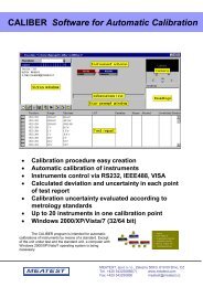
CaliberSoftware <strong>for</strong> automatic calibration of instrumentsDeterminationThe CALIBER program is intended <strong>for</strong>automatic calibrations of instruments.Except of the unit under test <strong>and</strong>the st<strong>and</strong>ard unit, a computer withWindows 2000/XP/Vista/7 OperatingSystem is being necessary. Output ofthe CALIBER program represents aphysically per<strong>for</strong>med calibrationwith a calibration record – a tablewith measured <strong>and</strong> evaluatedvalues (the test report).Typical workplaceSt<strong>and</strong>ard instruments controlledby the Caliber softwareBasic features••••••••••••••••••Easy creation of calibration procedures using Procedure wizardAutomatic calibration of instrumentsInstruments control via RS232, IEEE488, USB, RS485, Ethernet (VISA)Suitable <strong>for</strong> various instruments (meters, sources, transducers)Calculated deviation <strong>and</strong> uncertainty in each point of test reportSelectable rounding of measured <strong>and</strong> evaluated valuesCalibration uncertainty evaluated according to metrology st<strong>and</strong>ardsUp to 20 instruments in one calibration pointWindows 2000/XP/Vista/7 (32/64 bit)Instruments prepared <strong>for</strong>calibration“St<strong>and</strong>ard unit” <strong>and</strong> “Unitsunder test”UUT (Unit Under Test)St<strong>and</strong>ard (multifunction calibrator)MEATEST, spol. s r. o., Zelezna 3, CZ - 619 00 Brno, Czech Republic | tel. +420 543 250 886, 887 | fax +420 543 250 890 | e-mail: <strong>meatest</strong>@<strong>meatest</strong>.<strong>cz</strong> | www.<strong>meatest</strong>.com, www.<strong>meatest</strong>.<strong>cz</strong>Caliber/1
Program window descriptionInstruments schemeInstruments used in selectedcalibration point <strong>and</strong> theirconfigurationIn<strong>for</strong>mation lineDescription of per<strong>for</strong>medoperationUser prompt windowProgram messagesSet function <strong>and</strong> range manuallyM3800 Function VDC-2W Range 20 VCameraOptional camera module<strong>for</strong> digital display scanningStatus windowFunctionsRangesPointsActive terminalsconnectionExceptionsDirect keysNew / Open /SaveReload StartCalibrationImport / ExportTest reportMeasured <strong>and</strong> evaluated values (measured deviation, maximum allowed deviation, measurement uncertainty)Values are added during the calibration.ReadingsParticularmeasuredvaluesFunction| Range| St<strong>and</strong>ard | UUT| Deviation| %spe| Allowed | Uncert.|------------------------------------------------------------------------------------------------------------------------------------------------VDC-2W| 200 mV| 20.0 mV| 20.0 mV| -0 uV| 0| 200 uV| 62 uV| okVDC-2W| 200 mV| 180.0 mV| 180.6 mV| 620 uV| 62| 1003 uV| 71 uV| okVDC-2W| 200 mV| -180.0 mV| -180.7 mV| -690 uV| -69| 1003 uV| 69 uV| okVDC-2W| 2 V| 0.200 V| 0.200 V| -0.00 mV| 0| 2.00 mV| 0.58 mV| okVDC-2W| 2 V| 1.800 V| 1.807 V| 7.00 mV| 70| 10.04 mV| 0.58 mV| okVDC-2W| 2 V| -1.800 V| -1.807 V| -6.80 mV| -68| 10.03 mV| 0.64 mV| ok…Instruments schemeProgram uses special symbols <strong>for</strong> displaying different types of instruments in the “Instruments scheme” diagram. Up to 20 instruments canbe used in one calibration point.211M140Manual 25M3800Camera 110MOHMManual 43 6 4DAT1281GPIB23 31. Source2. UUT (meter)3. St<strong>and</strong>ard converter4. St<strong>and</strong>ard (meter)5. Master signal bus6. Trans<strong>for</strong>med busCaliber/2
Remote controlThe instruments can be operated either manually orautomatically (by computer). In automatic mode the interfaceRS232 or GPIB can be used, eventually any other interfaces (USB,Ethernet, RS485, …) which utilize the industry VISA st<strong>and</strong>ard.Caliber outputOutput of the CALIBER program represents a physicallyper<strong>for</strong>med calibration with a calibration record – a table withmeasured <strong>and</strong> evaluated data (the test report).Calibration procedureAutomatic calibration of UUTs is controlled through Calibrationprocedure. Calibration procedure is list of calibration points in thatorder, how they will be executed during calibration. Calibrationprocedure is different <strong>for</strong> different types of UUT. Calibrationprocedures <strong>for</strong> various UUT can be created direct in CALIBERprogram. For running, creating <strong>and</strong> modifying of calibrationprocedures, program module “Procedures” is aimed. Calibrationprocedure can be prepared in program CALIBER only.Procedure wizardProcedure wizard serves <strong>for</strong> convenient <strong>and</strong> easy preparingof new Calibration procedures. In general, “Instrument cards”determines action of the instruments which are connectedto the calibration system. “Calibration procedures” defineprocedure of the calibration, point by point. All basic programmodules are created in interactive way. Its generation doesn’trequire knowledge of programming.Instrument cardInstrument card contains description of metrological features ofan instrument (functions, ranges, specification etc.) <strong>and</strong> way ofinstrument control (GPIB, RS232 or VISA remote control comm<strong>and</strong>s).Instrument without instrument card can’t be used in calibrationprocedure. For creating <strong>and</strong> editing of instrument cards programmodule “Instrument card” is prepared.WinQbase-CaliberCaliber can be used either independently or as a part of databasesoftware package WinQbase. WinQbase is program <strong>for</strong> keepingrecords of various types of measuring instruments. It can be usedas a program superstructure of the Caliber system. It providesidentification of measuring instruments, of calibration sheets,record print, measuring instrument selection according to diversecriteria etc.Caliber program is specialized <strong>for</strong> automatic calibration ofinstruments. St<strong>and</strong>ard delivery contains functions <strong>for</strong> electricalquantity meters calibration. New functions <strong>for</strong> non-electricquantities can be defined by user <strong>and</strong> appropriate calibrationprocedures can be generated.MEATEST, spol. s r. o., Zelezna 3, CZ - 619 00 Brno, Czech Republic | tel. +420 543 250 886, 887 | fax +420 543 250 890 | e-mail: <strong>meatest</strong>@<strong>meatest</strong>.<strong>cz</strong> | www.<strong>meatest</strong>.com, www.<strong>meatest</strong>.<strong>cz</strong>Caliber/3
CamOCR (optional Camera module)CamOcr camera module extends possibilities of MEATEST automatic calibration software Caliber. CamOcr is designed <strong>for</strong> scanningof 7 segment digital displays.Instruments (UUT) without remote control interface can be “connected” using CamOcr to the computer. Instrument’s display is scannedby digital video camera. CamOcr converts scanned pictures into numbers. These numbers (measuring results) are used in <strong>for</strong> furthercalculations. It is very easy to do repeated measurements <strong>and</strong> calculate uncertainty type “A” <strong>for</strong> every calibration point.Instruments schemeInstruments used in selectedcalibration point <strong>and</strong> theirconfigurationIn<strong>for</strong>mation lineDescription of per<strong>for</strong>medoperationCameraReal view fromcameraReadingsReadingsValues readby cameraStatus windowInstrument’sconnection –used terminalsCaliber/4
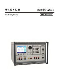
M-612 Precision RTD SimulatorM-612••••••••••••••••Calibration of temperature controllersResistance range from 16 Ω to 10k ΩSimulation of Pt <strong>and</strong> Ni sensorsAccuracy +/ – 0.02 °CTemperature stability < 1ppm/°C2, 3 <strong>and</strong> 4 wire connectionSimulation of cable resistanceVersion M-612 with RS-232M-612 GPIBM-612 S user defined RTDRTD simulator is aimed <strong>for</strong> testing <strong>and</strong> calibration of temperature controllers <strong>and</strong> thermometers which use RTD resistance temperaturesensor. It can simulate wide range of frequently used Pt/Ni sensors with high accuracy. The simulator can be applied also as fastprogrammable resistance decade. It is supplied from internal battery or via AC power line adapter. Manual or remote control through serialinterface RS-232 or GPIB is available.The simulator is suitable <strong>for</strong> calibration laboratories, service centers <strong>and</strong> <strong>for</strong> production lines where RTD sensor has to be simulated orresistance output is requested.SpecificationRange of temperature simulation: -200.000 °C – 850.000 °CSimulated temperature sensors: Pt100, Pt200, Pt500, Pt1000, Ni100, Ni1000Temperature scale:IPTS68, ITS90Pt sensor st<strong>and</strong>ard: DIN (1,385), US/JIS (1,392)Ni sensor st<strong>and</strong>ards: DIN 43760 (6180)Resistance range:16.0000 Ω – 10 000 ΩTemperature coefficient : < 1 ppm/ °CMaximal power dissipation:0.3 WMaximal current:100 mA in range 16 – 30 Ω / 50 mA in range 30 – 100 Ω20 mA in range 100 – 500 Ω / 10 mA in range 500 – 3000 Ω5 mA in range 3000 – 10000 ΩResistance accuracyRangeAccuracy16 Ω – 400 Ω 0.003 % + 3 mΩ400 Ω – 2000 Ω 0.005 %2000 Ω – 10000 Ω 0.015 %Pt sensors simulation accuracyNi sensors simulation accuracyTemperature range Accuracy Ni100 Accuracy Ni1000-60 … 300 °C 0.02 °C 0.1 °CTemperature range Accuracy Pt100 Accuracy Pt200 Accuracy Pt500 Accuracy Pt1000-200 … 200 °C 0.02 °C 0.02 °C 0.02 °C 0.03 °C200 … 500 °C 0.03 °C 0.04 °C 0.06 °C 0.15 °C500 … 850 °C 0.04 °C 0.06 °C 0.15 °C 0.20 °CConnection:Terminals:Remote control:Power supply:2, 3 or 4 wiregold plated terminals 4mminterface RS-232internal battery 12 V/2.6 Ahexternal power line adapterBattery operating period:typically 6 hoursReaction time:6 msRange of reference temperatures: 23 °C ± 5 °CDimensions:325 mm x 111 mm x 316 mmWeight:4 kgAccessories (included) <strong>for</strong> all M-612 versionsPower line adapter1 pcOperation manual1 pcCD with application SW1 pcRS-232 Cable (<strong>for</strong> RS-232 version only) 1 pcTest report1 pcGPIB cableoptionVersionsM612-V1000M612-V2xxxM612-Vx1xxM612-Vxx1xRTD simulator with RS-232, power line adapterRTD simulator with GPIB busSHORT/OPEN functions19” rack versionMEATEST, spol. s r. o., Zelezna 3, CZ - 619 00 Brno, Czech Republic | tel. +420 543 250 886, 887 | fax +420 543 250 890 | e-mail: <strong>meatest</strong>@<strong>meatest</strong>.<strong>cz</strong> | www.<strong>meatest</strong>.com, www.<strong>meatest</strong>.<strong>cz</strong>M-6x2/1
M-602/602AProgrammable Resistance Decade BoxM-602••••••••••••••Calibration of temperature controllersResistance range 0.10000 Ω – 10.0000 MΩAccuracy 0.02 %Temperature coefficient < 25 ppm/°CSimulation of Pt/Ni temperature sensorswith accuracy 0.2 °CInternal accumulator / power line adapterInterface RS 232 (IEEE488 optionally)Model M-602/602A is low cost programmable resistance decade box with total resistance range from 0.1 Ω to 10 MΩ in model M-602A<strong>and</strong> 10 Ω to 300 kΩ in model M-602. Best accuracy of resistance is 0.02 %. Value can be set with resolution 10 μΩ to 1 kΩ depending on setvalue. The decade box is designed from thick-metal resistors with temperature coefficient better than 25 ppm/ºC switched by combinationof relays. Build-in user interface contains function of RTD temperature sensor simulation with parameters according to IEC (DIN) or US/JIS st<strong>and</strong>ards <strong>and</strong> with temperature setting in degree of Celsius or Fahrenheit. The decade is supplied either from internal accumulator orfrom external power line adapter. Decade is available with RS-232 interface in basic version <strong>and</strong> with GPIB bus optionally. As option decadecan be delivered with SHORT/OPEN reference positions <strong>and</strong> in 19” rack version. Decade box is determined <strong>for</strong> calibration laboratories <strong>for</strong>ohmmeter <strong>and</strong> multimetr testing <strong>and</strong> <strong>for</strong> industry as device <strong>for</strong> quality testing.M-602 Resistance accuracy M-602A resistence accuracyRangeAccuracy10 Ω – 200 Ω 0.05 % + 15 mΩ200 Ω – 10 kΩ 0.02 %10 kΩ – 50 kΩ 0.05 %50 kΩ – 100 kΩ 0.1 %100 kΩ – 300 kΩ 0.5 %RangeAccuracy0.1 Ω – 200 Ω 0.05 % + 15 mΩ200 Ω – 2 MΩ 0.02 %2 MΩ – 10 MΩ 0.05 %M-602 Resistance resolution M-602A Resistance resolutionRangeResolution10.000 Ω – 300.000 Ω 0.001300.01 Ω – 1 000.0 Ω 0.011 000.1 Ω – 3 000.0 kΩ 0.13000 Ω – 10 000 Ω 110.00 kΩ – 30.00 kΩ 1030.0 kΩ – 100.0 kΩ 100100 Ω – 300 kΩ 1000RangeResolution0.100 00 Ω – 2.00000 Ω 10 uΩ2.000 1 Ω – 20.000 0 Ω 100 uΩ20.001 Ω – 200.000 Ω 0.001200.01 Ω – 2 000.00 Ω 0.012 000.1 Ω – 20 000.0 Ω 0.120 001 Ω – 200 000 Ω 1200.01 kΩ – 2 000.00 kΩ 102 000.1 kΩ – 10 000.0 kΩ 100M-602 Temperature sensor simulation accuracy M-602A Temperature sensor simulation accuracyTemperature Pt10 – Pt200 Pt201 – Pt20000-200 … 0 °C 0.2 °C 0.2 °C0 … 850 °C 0.2 °C 0.2 °CType of Pt sensors:IEC 751 PTS68/ITS90), US/JISType of Ni sensors: DIN 43760 (6180)Total power dissipation:0,3 WReaction time:6 msTerminals:gold plated terminals 4mmRange of reference temperatures: +18 °C … +28 °CRange of working temperatures: +5 °C … +40 °CTemperature Pt10 – Pt200 Pt201 – Pt20000-60 … 0 °C 0.2 °C 0.1 °C0 … 300 °C 0.1 °C 0.1 °CRemote control:RS232 interface(optionally IEEE488)Power supply:internal battery 12 V – 2.6 Ah (option)external power line adapterBattery operating period:typically 6 hourRange of storage temperatures: 10 °C … +50 °CDimensions:325 mm x 111 mm x 316 mmWeight:4.5 kgAccessories (included) <strong>for</strong> all M-602 versionsPower line adapter1 pcOperation manual1 pcCD with application software1 pcCable RS 232 (<strong>for</strong> RS232 basic version only) 1 pcTest report1 pcGPIB cableoptionVersionsM602/602A-V1000M602/602A-V2xxxM602/602A-Vx1xxM602/602A-Vxx1xM602/602A-Vxx2xM602/602A-Vxxx1RTD simulator with RS-232, power line adapterRTD simulator with GPIB busSHORT/OPEN functions19” rack versionwith housing holderACCU operationM-6x2/2
M-622 Precision Programmable Resistance Decade BoxM-622••••••••••••••••••Calibration of temperature controllersResistance range 1.00000 Ω – 1.200 000 MΩAccuracy 0.005 %Temperature coefficient < 1ppm/°COperating voltage 120 VSimulation of Pt/Ni temperature sensorsSimulation accuracy 0.02 °CInternal accumulator / power line adapterInterface RS 232 (IEEE488 optionally)Resistance decade M-622 is precise programmable resistance decade in range 1.000 00 Ohm to 1 200 000 Ohm. It is designed <strong>for</strong> checkingof parameters of resistance meters <strong>and</strong> regulators <strong>and</strong> process meters, which use external resistance sensors <strong>for</strong> non-electric quantitymeasuring. Set resistance value is created via appropriate combination of physical resistors. Decade is equipped with build-in function ofdirect simulation of most frequent temperature Pt <strong>and</strong> Ni sensors. Low thermal voltage relays <strong>and</strong> stable foil resistors with low temperaturecoefficient are used as main parts of the decade. Actual set values are displayed on the front panel display. Resistance decade is suppliedfrom internal battery. External power line adapter is delivered as power line source <strong>and</strong> as internal battery charger in one. M-622 issophisticated instrument with its own re-calibration procedure. The procedure enables to correct any deviation in resistance without anymechanical adjusting.Resistance accuracyOutput terminals Range AccuracyR4W 1 Ω - 400 Ω 0.003 % + 3 mΩR4W 400 Ω - 2000 Ω 0.005 %R4W 2000 Ω - 10000 Ω 0.015 %R2W 1 Ω - 2000 Ω 0.005 % + 10 mΩR2W 2 kΩ - 200 kΩ 0.005 %R2W 200 kΩ - 1200 kΩ 0.01 %Resistance resolutionRangeResolution1.000 00 Ω - 10.000 00 Ω 10 uΩ10.000 1 Ω - 100.000 0 Ω 100 uΩ100.001 Ω - 400.000 Ω 0.001400.01 Ω - 1 200.00 Ω 0.011 200.1 Ω - 30 000.0 Ω 0.130 000 Ω - 1 200 000 Ω 1Pt sensor temperature simulation accuracyTemperature Pt100 Pt200 Pt500 Pt1000 (terminals R4W) Pt1000 (terminals R2W)-200 … 200 °C 0.02 °C 0.02 °C 0.02 °C 0.04 °C 0.04 °C200 … 500 °C 0.03 °C 0.04 °C 0.06 °C 0.1 °C 0.06 °C500 … 850 °C 0.04 °C 0.06 °C 0.15 °C 0.2 °C 0.1 °CNi sensor temperature simulation accuracyTemperature Ni100 (terminals R4W) Ni1000 (terminals R4W) Ni10000 (terminals R2W)-60 … 300 °C 0.02 °C 0.04 °C 0.04 °CPt temperature range: -200.000 °C … 850.000 °CNi temperature range: - 60.000 °C … 300.000 °CType of Pt sensors:IEC 751 PTS68/ITS90), US/JISType of Ni sensors: DIN 43760 (6180)Total power dissipation: 0,3 WReaction time:6 msTerminals:gold plated terminals 4 mmRemote control:RS232 interface (optionally IEEE488)Power supply:internal battery 12 V – 2.6 Ahexternal power line adapterBattery operating period:typically 6 hourRange of reference temperatures: +18 °C … +28 °CRange of working temperatures: +5 °C … +40 °CRange of storage temperatures: -10 °C … +50 °CDimensions :325 mm x 111 mm x 316 mmWeight:4.5 kgAccessories (included)VersionsPower line adapterOperation manualCD with application softwareCable RS 232 (<strong>for</strong> RS232 basic version only)Test reportGPIB cable1 pc1 pc1 pc1 pc1 pcoptionM622-V1000M622-V2000M622-Vx1xxM622-Vxx1xDecade box with RS-232, power line adapterDecade box with GPIB busSHORT/OPEN functions19” rack versionMEATEST, spol. s r. o., Zelezna 3, CZ - 619 00 Brno, Czech Republic | tel. +420 543 250 886, 887 | fax +420 543 250 890 | e-mail: <strong>meatest</strong>@<strong>meatest</strong>.<strong>cz</strong> | www.<strong>meatest</strong>.com, www.<strong>meatest</strong>.<strong>cz</strong> M-6x2/3
Easy recalibrationAll models of the series M6x2 are equipped with recalibration capability using front panel keypad.R0062.00000 Ω62.0200Calibration data off all partial resistors in the decade can be verified <strong>and</strong> new values storedinto calibration memory.Access to the calibration memory is protected with password.Application of M-6x2 seriesResistance ranges of meters, thermometers calibrationLED indicated2W functionDecade displayR mode1. Select function R2. Select 4 W/2 W3. Set value 0 Ohm4. Set requested valueusing numerical keypad5. Press ENTERCalibration of heat meters usingtwo RTD simulators M-61212RTD Simulator simulates temperature of input<strong>and</strong> output watter of the rating system.M-6x2/4
M-109RHigh Resistance Decade••••••••••••Calibration of insulation meters<strong>and</strong> megaohmmeters4 decadesRange 1 MOhm – 12 GOhmMaximum working voltage 5 kVInternal battery or powerline adapter supplyingRS 232 controlM-109RHigh resistance decade box is designed <strong>for</strong> calibrating of insulation meters <strong>and</strong> megaohmmeters. It is suitable <strong>for</strong> calibration laboratories<strong>and</strong> service centres, where can be used also <strong>for</strong> testing or setting of high resistance meters. High voltage relays with extremely highinsulation resistance are used <strong>for</strong> switching of resistance components.M-109R is equipped with indication of input terminal overload. Instrument is supplied from accumulator or power line adapter.Control is possible manually or remotely via serial interface RS-232.SpecificationRange of resistance: 1 MΩ - 12.221 GΩMaximum voltage:5kV DC between terminals H-L, H-GND, L-GNDConnection:two-terminal, three-terminal (GUARD)Type of terminals:high voltage terminals with ERTALYTE isolationRemote control:serial interface RS-232Supply:internal accumulator, power line supply adapter 15 V (100-240 V/50-60 Hz)Temperature range: 23 °C ± 5 °CRelative humidity: 10 - 50 %Dimensions:364 mm x 111 mm x 316 mmWeight:4 kgAccuracyDecade Nominal value accuracy Voltage coefficient Temperature coefficient Maximum voltage[ % ] [ ± ppm/V ] [ ± ppm/ °C ] [ VDC/RMS ]1 MΩ - 11 MΩ 0.1 1 < 100 1000/70010 MΩ - 110MΩ 0.2 1 < 100 2500/1700100 MΩ - 1.1 GΩ 0.5 2 < 100 5000/35001 GΩ - 12 GΩ 1.0 2 < 100 5000/3500Basic accessory (included)Power line adapterCable RS-232CD with application softwareUser’s manualTest reportOptions (extra ordered)Test lead 5000 VDC / 20 AMEATEST, spol. s r. o., Zelezna 3, CZ - 619 00 Brno, Czech Republic | tel. +420 543 250 886, 887 | fax +420 543 250 890 | e-mail: <strong>meatest</strong>@<strong>meatest</strong>.<strong>cz</strong> | www.<strong>meatest</strong>.com, www.<strong>meatest</strong>.<strong>cz</strong>M-109R/1
Front panelOutput teminals2W resistanceLED indicatedmaximum input voltageIndividualrotary buttonsGND terminalprotection earthLED indicatedswitching the decade onLED indicatedmod of remote controlApplicationCalibration <strong>and</strong> verification of meters with test voltage up to 5 kVDC:- Insulation testers- Safety testers- Megaohmmeters- OhmmetersLED Indicatedmaximum input voltageLED indicatedswitching the decade on1. Press ON/OFF button2. Set requested value usingindividual rotary buttonsM-109R/2
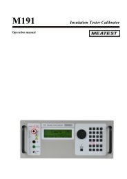
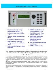
M191Insulation Tester CalibratorHigh Ohm 10 kV Programmable Decade BoxM191••••••Programmable high voltage high resistancedecadeResistance range from 10 kΩ to 1 TΩWorking voltage range up to 10 kV DC••••••SHORT function <strong>for</strong> short current testingSpecial function <strong>for</strong> Timer testingVerification of dielectric absorption ratio<strong>and</strong> polarization indexes measurement••Grounded or floating operation••Easy recalibration using front panel keypad••Built-in three high voltage capacitors of fixvalues from 10nF to 100 nF••GPIB & RS232 interface••Built-in high voltage voltmeterM191 Insulation tester calibrator is a device designed <strong>for</strong> application field of calibration of insulation testers.It can be used <strong>for</strong> calibration of any DC high resistance meter with working voltage up to 10 kV.M191 calibrator is based on programmable high resistance decade which is completed with additional electronic circuits allowingcalibration not only resistance ranges, but also calibration of test voltage generated by UUT, testing of short current, verifying of functionsof measuring dielectric parameters like polarization index (PI), dielectric absorption ratio (DAR) <strong>and</strong> polarization ratio (PR). The calibratorenables also verification of timer function of UUTs.Basic feature of the calibrator is adjustable high resistance decade in summary range from 10 kΩ to 1 TΩ. The decade is designed <strong>for</strong>operation voltages up to 10 kV. In this range it offers basic accuracy 0.1% to 5 % depending on set resistance value.The calibration can be controlled manually using front panel keypad or in remote mode using one of two types of interfaces GPIB,RS-232. The calibrator can easily fit within calibration systems featuring CALIBER software support.MEATEST, spol. s r. o., Zelezna 3, CZ - 619 00 Brno, Czech Republic | tel. +420 543 250 886, 887 | fax +420 543 250 890 | e-mail: <strong>meatest</strong>@<strong>meatest</strong>.<strong>cz</strong> | www.<strong>meatest</strong>.com, www.<strong>meatest</strong>.<strong>cz</strong>M191/1
HVR High resistance source modeThe calibrator basic function is High resistance source mode. In this mode any resistance value in range from 10 kΩ to 1 TΩ adjustable with4 digit resolution can be set <strong>and</strong> connected to the output terminals. Maximum allowed working DC voltage is from range 50 V to 10 000 Vdepending on set resistance. Switching the resistance value under test voltage is allowed in limited voltage range.Following in<strong>for</strong>mation are displayed on the display:- Set resistance value in Ω.- Maximum safe test voltage which is allowed to apply to the outputterminals.- Applied test voltage. This is value of DC test voltage sourced by UUT <strong>and</strong>connected to the calibrator output terminals.- Test current. Calibrator calculates <strong>and</strong> displays test current.- Accuracy. Calibrator displays accuracy of selected resistance point in %.HVC High voltage capacitanceIn High voltage capacitance function the calibrator enables to connect to the output terminals one of three high voltage capacitors whichare built-in the calibrator. Sense of the capacitance function is to offer tool <strong>for</strong> calibration of those megaohmmeters <strong>and</strong> insulation testerswhich can measure also capacitance. The calibrator is equipped with 3 capacitors with nominal values 10, 50, 100 nF. Maximum test voltageis 5 000 VDC.When in HVC mode the display shows in<strong>for</strong>mation as follows:- Calibration value of the selected capacitor.- Vmax. Maximum allowed DC test voltage.- Test voltage. To the output terminals currently connected testvoltage.- Accuracy of the set capacitance in %.SHORT Short current modeShort current mode is designed to enable verification of short current capability of UUTs - megaohmmeters. M191 measures DC test currentwhich is sourced by UUT under short circuit condition. M191 milliampermeter has one range 5 mA with five-digit resolution in this mode.Nominal input resistance is 2.5 kΩ.Display shows in<strong>for</strong>mation as follows:- Measured short current in mA.- Accuracy of the measured value in %.TIMER Timer functionTimer function allows verifying timer features of safety testers <strong>and</strong> megaohmmeters. Calibrator can measure time interval <strong>for</strong> what the UUTtest voltage is presented on the calibrator output terminals. During the measurement the calibrator goes automatically through sequenceof states: OFF, STANDBY, RUNNING, OFF. In Timer function calibrator automatically connects to the output terminals resistance value 100MΩ. The value cannot be modified.Display shows in<strong>for</strong>mation as follows ( St<strong>and</strong>by mode):- Measured time in seconds.- Maximum DC test voltage which has been caught by the calibratorduring time interval of the Timer calibration.- Test voltage. Current test voltage presented on the calibrator outputterminals during calibration process.- Accuracy of the measured time interval.M191/2
DPP & PSP Dielectric <strong>and</strong> polarization parametersDPP & PSP functions enable direct calibration of isolation meters which are equipped with function of DAR (dielectric absorption ratio), PI(polarization index) or PR (polarization ratio). Operation of the functions is based on switching different values of resistance to the outputterminals in predefined time sequence.Following parameters can be entered in DPP mode:- DAR/PR/PI PARAMETER can be selected.- Basic resistance level given by R0 parameter.The parameter range is from 10 MΩ to 100 GΩ.- DAR/PR/PI coefficient in range from 0.5 to 99.9.DPP is preprogrammed mode with time sequences of DAR/PR/PI parameters. PSP mode is programmable mode. The resistances connectedto the output terminals can be preset in range 10 MΩ to 100 GΩ <strong>and</strong> can be switched over in programmable time intervalup to 9 999 s.In the PSP mode any resistance values can be set <strong>and</strong> switched to theoutput terminals in predefined intervals.SpecificationAccuracy includes long-term stability, temperature coefficient, linearity, load <strong>and</strong> line regulation <strong>and</strong> the traceability of factory <strong>and</strong>National calibration st<strong>and</strong>ards. Specified accuracy is valid after one hour warm up in temperature range 23 ± 2 ºC. Specified accuracy isone year accuracy.Function HVR (High resistance programmable decade box)Total resistance range: 10.00 kΩ to 1000.0 GΩAccuracy in grounded mode (G) <strong>and</strong> floating mode (F):Resistance rangeΩAccuracy in Gmode* %Accuracy in Fmode* %Maximum DC testvoltage*** VTypical voltagedependencyppm/VTest voltageaccuracyTest current rangeATest currentaccuracy10.00 k – 99.99 k 0.2 0.2 50 < 0.05 0.5 % + 10 V 10 m 0.7 % + 100 uA100.0 k – 999.9 k 0.1 0.1 250 < 0.05 0.5 % + 10 V 2.5 m 0.7 % + 10 uA1.000 M – 9.999 M 0.1 0.1 1 000 < 0.05 0.5 % + 10 V 1 m 0.7 % + 1 uA10.00 M – 99.99 M 0.1 0.1 5 000 < 0.05 0.5 % + 10 V 500 u 0.7 % + 100 nA100.0 M – 499.9 M 0.1 0.1 10 000 < 0.05 0.5 % + 10 V 100 u 0.7 % + 20 nA500.0 M – 999.9 M 0.2 0.2 10 000 < 0.07 0.5 % + 10 V 20 u 1 % + 10 nA1.000 G – 9.999 G 0.5 0.5 10 000 < 0.15 0.5 % + 10 V 10 u 1.5 % + 1 nA10.00 G – 19.99 G 0.5 1.0 10 000 < 0.15 0.5 % + 10 V 1 u 1.5 % + 500 pA20.00 G – 99.99 G 1 2 10 000 < 0.20 0.5 % + 10 V 500 n 2 % + 100 pA100.0 G – 299.9 G 2 3 10 000 < 0.20 0.5 % + 10 V 100 n 5 % + 20 pA299.9 G – 1000.0 G 5 6 10 000 < 0.20 N/A** N/A** N/A*** Accuracy is valid in reference temperature range 23+/-2 °C with RH < 50%.** Test voltage voltmeter function is not available in resistance range from 299.9 GΩ to 1 000 GΩ.Maximum measured DC test voltage is 5% over the specified range***Test voltage range:Maximum applied voltage during over-switching:Test voltage indication:Test voltage accuracy:Test current indication:Maximum safe DC voltage between H <strong>and</strong> L terminal:Maximum allowed DC voltage between L <strong>and</strong> GND terminal:10 000 VDC + 5% over range3 000 VDC (without output terminals disconnection)4 digit meter with range to 10 kVDCwith suppressed indication bellow 50 VDC0.5 % + 10 V4 digit meter in range from 0.01 pA to 99.99 mADC11 000 VDC15 VDCMEATEST, spol. s r. o., Zelezna 3, CZ - 619 00 Brno, Czech Republic | tel. +420 543 250 886, 887 | fax +420 543 250 890 | e-mail: <strong>meatest</strong>@<strong>meatest</strong>.<strong>cz</strong> | www.<strong>meatest</strong>.com, www.<strong>meatest</strong>.<strong>cz</strong>M191/3
SHORT function <strong>for</strong> Short test current verificationCurrent range:0.000 – 5.000 mA DCInput resistance:250 Ω nom.Short test current accuracy: 0.2% + 5 uATIMER function, verification of Timer featureRange of the timer:1 s to 9 999 sTimer accuracy:(0.3+0.0001* t) s where t is elapsed timeThreshold voltage:< 100 VDC,Maximum test voltage:10 000 VDC + 5 % over rangeOutput resistance:100 MΩTest voltage indication:0 to 10 000 V DC with suppressed indication bellow 50 VDCTest voltage accuracy:0.5 % + 10 VMax. test voltage hold function: to 11 kV DCPSP function, programmable simulation of polarization parametersNumber of switching positions: 4Applicable resistance range: 10.00 MΩ to 100.00 GΩMaximum allowed test voltage: 3 000 VDCMax. period setting:9 999 sDPP function DPP, Dielectric <strong>and</strong> polarization parametersApplicable resistance range: 10.00 MΩ to 100.00 GΩMaximum allowed test voltage: 3 000 VDCMax. period setting:9 999 sPreset parameters:Polarization index (PI)Dielectric absorption ratio (DAR)Polarization ratio (PR)HVC function, high voltage capacitanceRange of capacitance:10, 50, 100 nF fix valuesTolerance: ± 10 %Calibration value uncertainty: 0.3 %Max. test voltage:5 000 VDC + 5 % over rangeTest voltage indication:0 to 5 000 V DC with suppressed indication bellow 50 VDCTest voltage accuracy:0.5 % + 10 VGeneral dataWarm up time:15 minutesOperating temperature: 23 ± 10 ºC, Relative humidity < 70%Reference temperature:23 ± 2 ºC,Relative humidity < 50 % <strong>for</strong> resistance range from 10 GΩ to 1 000 GΩRelative humidity < 70 % <strong>for</strong> resistance range from 10 kΩ to 10 GΩTemperature coefficient:Additional resistance uncertainty due to temperature coefficient <strong>for</strong> temperature outsideof Tcal±2°C:from +13 °C to +33 °C add 0.1 x specified accuracy /°C at reference temperatureHumidity coefficient:Additional uncertainty due to humidity coefficient in range 50 to 70 % RH is:- 0.15 x specified accuracy / % RH <strong>for</strong> range 10.00 GΩ to 1 000.0 GΩ- 0.05 x specified accuracy / % RH <strong>for</strong> range 100.0 MΩ to 9.99 GΩ- 0.02 x specified accuracy / % RH <strong>for</strong> range 10.00 GΩ to 99.99 GΩStorage temperatures: -10 ºC to +55 ºCDimension:450 (W) x 430 (D) x 150 (H) mmNetto weight12 kgPower line:110/115/120/125 – 220/230 V – 50/60 HzPower consumption:40 VASafety class: I according to EN 1010-1Accessories (included)Power cord 1 pc Spare fuse 2 pcsOperation manual 1 pc Test lead 30V/20A 2 pcsTest report 1 pc Test lead 5000V /20A 1 pcRS232 CableAvailable extra ordered optionsGPIB Cable 2mTest lead 30V/20ATest lead 5000V/20AM191/4
M-192/192AProgrammable AC/DC LoadHigh Power Programmable Resistance Decade Box3000 W••••••••Resistance range 15 Ω to 300 kΩMaximal load 3 kWMaximal voltage 250 V RMSAccuracy 0.1 %••••••••Temperature coefficient < 10 ppm/°C2, 4 – wire connectionInterface RS – 232 (IEEE488 optionally)Table version (19“ module as option)M-192 AC/DC load is determined <strong>for</strong> testing voltage sources, trans<strong>for</strong>mers or generally as power load up to 3 kW. Load is especially suitable<strong>for</strong> automated testing systems.Thanks to good accuracy <strong>and</strong> remote control feature M-192 load can be used in calibration laboratories, production lines, service centers<strong>and</strong> development departments. For use in industry is designed version in 19“ module with height 4 HE.Among advantages belongs features like simple control from the front panel, indication of set-up values on LCD display, resistance, power<strong>and</strong> current modes, remote control via RS-232 or IEEE488 bus.SpecificationResistance range15 Ω - 4700 Ω / 15 Ω - 300 kΩ (version M-192A)Resolution0.1 Ω to 1 Ω <strong>for</strong> M-192 version, 0.001 Ω to 1 kΩ <strong>for</strong> M-192A versionTemperature coefficient< 10 ppm/°CMaximal dissipation power3000 WMaximal voltage250 V RMSInternal voltmeter (M-192A only)range 300V AC/DC, AC/DC automatic selection, resolution 0.1 VConnection2, 4 wiresRange of reference temperatures +18 °C … +28 °CRange of operating temperatures +5 °C … +45 °CStoring temperatures -10 °C … +60 °CHousingmetalDimensions <strong>and</strong> weightW 460 mm, H 190 mm, D 440 mm (without holders), 15 kgIsolation resistance between signal outputs <strong>and</strong> housing> 2 GΩ (at 1000 Vdc)Content of deliveryM-192/192A Programmable AC/DC LoadOperation manualPower cableTest reportVersionsInterfaceHousingM192-V1xxx - RS232M192-V2xxx – IEEE488M192-Vxx0x – table versionM192-Vxx1x - module 19“, 4 HEMEATEST, spol. s r. o., Zelezna 3, CZ - 619 00 Brno, Czech Republic | tel. +420 543 250 886, 887 | fax +420 543 250 890 | e-mail: <strong>meatest</strong>@<strong>meatest</strong>.<strong>cz</strong> | www.<strong>meatest</strong>.com, www.<strong>meatest</strong>.<strong>cz</strong>M192/1
Resistance accuracy (M-192 only up to 4700 Ω)RangeAccuracyDC…120Hz 120Hz…1kHz 1kHz…10kHz15.000 Ω - 99.999 Ω 0.1 % + 30 mΩ 0.2 % + 30 mΩ 0.2 % + 30 mΩ100.000 Ω - 3.000 kΩ 0.1 % 0.1 % 0.2 %3.001 kΩ - 30.00 kΩ 0.1 % 0.1 % 2,00%30.1 kΩ - 100.0 kΩ 0.2 % 0.2 % —101 kΩ - 300 kΩ 0.5 % 2,00% —Internal voltmeter (M-192A only)RangeAccuracyDCAC1.0 - 299.9 V 0.1 % + 0.2 V 0.2 % + 0.2 VTypical frequency response (M-192A)R nom100Hz 1kHz 10kHz 100kHz 1MHz15 Ω Z [Ω] 15 15 15 15,03 15,15Ø [°] 0 0,03 0,26 2,4 23100 Ω Z [Ω] 100 100,01 100,02 99,97 91,5Ø [°] 0 0,01 0,08 0,75 9,1330 Ω Z [Ω] 330 330,02 330,03 329,73 301,3Ø [°] 0 0 0,01 0,08 4,11000 Ω Z [Ω] 1000 1000 999,9 997 854Ø [°] 0 -0,02 -0,18 -1,7 -910 kΩ Z [kΩ] 10 10 9,97 9,21 3,15Ø [°] -0,02 -0,23 -2,2 -19 -57100 kΩ Z [kΩ] 100 99,78 91,7 27 N.A.Ø [°] -0,18 -2,3 -20,5 -70,4ApplicationBattery testingLoad display R modeOutput terminals2 W/ 4 WU15.206 Ω0.0 VBattery chargertestingAC/DC Supplysources testing1. Set requested value usingnumerical keypad or kursorkeys2. Press ENTER3. Press ON/OFFAmplifier testingTrans<strong>for</strong>mer testingM192/2
MTELF Resistance/Capacitance/Inductance St<strong>and</strong>ardsMTE••••••••••Traceability of electric quantitiesCalibration of metersCalibration uncertainty 0.005 %Low time constantThree/four terminal or four pair terminalconnectionResistance/Capacitance st<strong>and</strong>ards of series MTE are designed <strong>for</strong> calibration of ohmmeters, RCL meters, insulation testers calibration. Theycan be applied as a mean of traceability of electric resistance between primary <strong>and</strong> secondary laboratories.DC modification of the st<strong>and</strong>ards is equipped with 4 mm terminal socket. Resistance st<strong>and</strong>ards up to 1 MΩ are in four-terminal connectionwhile st<strong>and</strong>ards over 10 MΩ have two terminal connection with additional insulation washer <strong>and</strong> with grounding terminal connected tothe housing.AC resistance versions <strong>and</strong> capacitance/inductance st<strong>and</strong>ards are delivered with four BNC connectors enabling application in threeterminal,four-terminal, four-pair terminal configuration. As a part of MTE set <strong>for</strong> AC applications the reference positions OPEN <strong>and</strong> SHORTterminals can be delivered. Both components serve typically <strong>for</strong> zero calibration of RCL meters.Other type of connectors can be installed on request. Other nominal values can be delivered on request.LF Capacitance st<strong>and</strong>ards MTE seriesConnectionType of terminalsFrequency rangeFour pair terminalBNC coaxial connectors <strong>for</strong> AC applications20 Hz - 20 kHz to 1 nF, 20 Hz – 10 kHz to 100 uFModel Nominal value Accuracy1 kHz calibrationuncertaintyTemperaturecoefficientDissipation factor[ % ] [ % ] [ ± ppm / °C ] [ - ] TypeCP – 10p 10 pF 1 0.01 15 ≤ 0.001Ceramic multilayerSilver micaCP – 100p 1 00 pF 0.1 0.01 15 ≤ 0.001Ceramic multilayerSilver micaCP – 1n 1 000 pF 0.1 0.01 15 ≤ 0.0005 Silver micaCP – 10n 10 000 pF 0.1 0.01 15 ≤ 0.0005 Silver micaCP – 100n 100 000 pF 0.1 0.01 15 ≤ 0.0005 Silver micaCP – 1u 1 uF 0.1 0.01 50 ≤ 0.0005 PolypropylenCP – 10u 10 uF 0.2 0.1 50 ≤ 0.005 PolypropylenCP – 100u 100 uF 0.2 0.1 50 ≤ 0.005 PolypropylenNoteMEATEST, spol. s r. o., Zelezna 3, CZ - 619 00 Brno, Czech Republic | tel. +420 543 250 886, 887 | fax +420 543 250 890 | e-mail: <strong>meatest</strong>@<strong>meatest</strong>.<strong>cz</strong> | www.<strong>meatest</strong>.com, www.<strong>meatest</strong>.<strong>cz</strong>MTE/1
LF Inductance st<strong>and</strong>ards MTE seriesConnectionType of terminalsFrequency rangeFour pair terminalBNC coaxial connectors100 Hz – 20 kHzModel Nominal value Accuracy 1 kHz calibrationuncertaintyTemperaturecoefficientMin. quality factor<strong>for</strong> f=1 kHz[ % ] [ % ] [ ± ppm / °C ] [ - ] TypeLP – 100m * 100 mH 0.5 0.05 50 ≥ 3 *** T-networkLP – 1** 1 H 0.5 0.05 50 ≥ 3 T-networkLP – 10 10 H 0.5 0.05 50 ≥ 10 T-networkLP – 100 100 H 0.5 0.05 50 ≥ 10 T-networkLP – 1000 1000 H 0.5 0.05 50 ≥ 10 T-networkT network is composed from two resistors <strong>and</strong> one capacitor. The network can simulate inductance parameter L21 with Q factor over 3 in recommended frequency area.The st<strong>and</strong>ard can be applied <strong>for</strong> calibration of those RCL meters which measure test current in Low input terminal. The st<strong>and</strong>ard cannot be applied <strong>for</strong> calibration of classic trans<strong>for</strong>mer bridges.* Applicable frequency range from 10 to 20 kHz; ** Applicable frequency range from 1 kHz to 20 kHz; *** Q factor <strong>for</strong> frequency 10 kHzNoteLF Resistance st<strong>and</strong>ards MTE seriesConnection3-terminals (above 10 MΩ), 4-terminals or 4 pair-terminals (bellow 10 MΩ)Housing type MTE1 <strong>for</strong> general application with BNC terminals or gold plated terminalsDimensions 125 x 60 x 105 mmM-530 <strong>for</strong> RCL meter calibration designed <strong>for</strong> direct connection to the front panelconnectors with two fixing female BNC screwsDimensions 105 x 33 x33 mmType of terminalsBNC coaxial connectors <strong>for</strong> AC applications (0.1 Ω to 10 MΩ)Gold plated terminals <strong>for</strong> DC applications (0.1 Ω to 10 MΩ)St<strong>and</strong>ard terminals with additional ertallyte isolation (above 10 MΩ)Frequency rangeDC to 20 kHz <strong>for</strong> nominal value 0.1 Ω to 10 MΩ (with BNC connectors)Model Nominal Value AccuracyDC calibrationuncertaintyTemperaturecoefficient *Power rating **[ % ] [ % ] [ ± ppm / °C ] [ W ] Resistance segmentRP – 0.1 100 mΩ 0.1 0.05 10 3 Foil resistorRP – 1.0 1 Ω 0.05 0.01 10 3 Foil resistorRP – 1.0 1 Ω 0.05 0.01 1 3 Foil resistorRP – 10 10 Ω 0.01 0.005 1 0.3 Foil resistorRP – 100 100 Ω 0.01 0.005 1 0.3 Foil resistorRP – 1k 1 kΩ 0.01 0.005 1 0.3 Foil resistorRP – 10k 10 kΩ 0.01 0.005 1 50 V *** Foil resistorRP – 100k 100 kΩ 0.01 0.005 1 150 V *** Foil resistorRP – 1M 1 MΩ 0.01 0.005 1 500 V *** Foil resistorRP – 10M 10MΩ 0.05 0.01 100 2 500 V*** Ceramic resistorRP – 100M 100 MΩ 0.5 0.1 100 2 500 V*** Ceramic resistorRP – 1G 1 GΩ 1 0.3 100 5 000 V*** Ceramic resistorRP – 10G 10 GΩ 3 0.5 100 5 000 V*** Ceramic resistor* in temperature range 0–50 °C; ** <strong>for</strong> ambient temperature 23 °C; *** maximal voltageNoteMTE/2
M-530 RF Resistance/Capacitance St<strong>and</strong>ardsM-530••••••••Resistance range 10 Ω to 1000 ΩVery low frequency dependencyApplicable frequency range to 100 MHzCalibration of wide frequency rangeLCR metersThe resistance st<strong>and</strong>ard set is designed especially <strong>for</strong> calibration of LCR meters in frequency range from DC to 100 MHz. The st<strong>and</strong>ards areequipped with four coaxial BNC connectors. Wide frequency range is achieved by applied HF design using strip line technology. Four-pairterminal connection with 22 mm distance between them enables direct connection to the UUTs without need to apply test leads.The st<strong>and</strong>ards are available with nominal value 10, 50, 100, 500, 1000 Ω in 1% tolerance. Reference positions OPEN <strong>and</strong> SHORT <strong>for</strong> easy“zero” compensation are available as well.10dR (%)f (MHz)10.001 0.01 0.1 10 100 10000.11000 R500 R0.0110&100 R50 R0.001Frequency dependencyApplicable frequency range of the resistancest<strong>and</strong>ards depends on nominal resistance value <strong>and</strong>requested maximal deviation.Typical frequency characteristics are shown in thediagram.0.0015P (mW)0.01 0.10-5-10-15-20-25-30dR (ppm)10-35Load parametersMaximal electric power dissipated in the st<strong>and</strong>ardsis limited due to small size of applied resistivesegments.Typical relative change of the resistance value whenloaded with 5 mW electric power is shown in thegraph bellow.MEATEST, spol. s r. o., Zelezna 3, CZ - 619 00 Brno, Czech Republic | tel. +420 543 250 886, 887 | fax +420 543 250 890 | e-mail: <strong>meatest</strong>@<strong>meatest</strong>.<strong>cz</strong> | www.<strong>meatest</strong>.com, www.<strong>meatest</strong>.<strong>cz</strong>M-530/1
Time constantExtremely low time constant of the resistance st<strong>and</strong>ards is given by high frequency design <strong>and</strong> RF resistance segments.The time constant value is in order of 10 -10 to 10 -11 s.Temperature coefficientTypical temperature coefficient is 0.2 ppm/°C <strong>for</strong> nominal values 10, 50, 100 Ω <strong>and</strong> 15 ppm/°C <strong>for</strong> values 500 <strong>and</strong> 1000 Ω.Technical specificationModelNominal valueMax. deviation tonominal valueMaximal frequency<strong>for</strong> 0.1% deviationMaximal frequency<strong>for</strong> 1% deviationTime constantTemperaturecoefficientMaximal testcurrentΩ % MHz MHz s ppm/°C mAM530–10R 10 1 2 200 < 2.10–10 < 1 40M530–50R 50 1 10 > 500 < 2.10–10 < 1 20M530–100R 100 1 2 200 < 5.10–11 < 1 12M530–500R 500 1 0.5 50 < 2.10–10 < 25 6M530–1000R 1000 1 0.1 10 < 2.10–10 < 25 4OPEN — — 2 200 — — —SHORT 0 — 2 200 — — 100Self-inductance:< 0.08 μHConnection:4 x BNC male connectorDistance between connectors: 22 mmDimensions:105 x 34 x 50 mm (including connectors)Housing:aluminumRange of working temperatures: 15 – 30 °CApplicationCalibration of LCR metrersThe st<strong>and</strong>ards are equipped with BNC connectors with spacing which equells spacing of input terminals of most frequently used LCRmeters.Calibration in this way excludes thé most significant uncertainties related to cabelling.M-530/2
TM-185DTemperature/ Humidity MonitorTM-185D••••••••••••Temperature <strong>and</strong> relative humiditymeasurementReal time dataLarge LED displayData logging capacity 30 000 recordsAlarm set <strong>for</strong> Hi <strong>and</strong> Low limitTemperature <strong>and</strong> HumidityUSB interfaceTM-185D is measuring instrument, which measures, displays <strong>and</strong> saves in<strong>for</strong>mation about reference conditions in laboratories.It measures ambient temperature <strong>and</strong> relative humidity. Wide time range of ambient conditions can be scanned <strong>and</strong> recorded by settingof appropriate interval of recording. When power line supplying is interrupted, monitor operates from internal back-up source withoutlosing any <strong>for</strong>merly stored data.TM-185D can be used independently or as a part of automated calibration systems. It is supported by calibration software WInQbase.Basic delivery contains the instrument with temperature/humidity sensor, AC/DC adapter <strong>and</strong> software <strong>for</strong> transferring of measured valuesto a PC. The instrument ensures the requirements of st<strong>and</strong>ards ISO 9000/45001, which calibration laboratory have to fulfil.Technical parametersTemperatureTemperature range: -20 … 60 °CTemperature accuracy:Temperature resolution: 0.1 °CUpdate rate:1 sRelative humidityHumidity range:Humidity accuracy:Humidity resolution: 0.1 %Update rate:4 s1 °C (in range -5 … 40 °C)2 °C (outside the range -5 … 40 °C)5 - 95 % RH2 % (in range 25 °C, 35 … 80 % RH)2.5 % (in range 25 °C, 10 … 35 <strong>and</strong> 80 … 90 % RH)5 % (<strong>for</strong> 25 °C, other ranges)General parametersData logger capacity 30000 samplesPower supplyAC/DC adapter 9V/1A, backup battery 9VInterfaceUSBSize260 x 178 x 47 mmWeight1000 gOther functions temperature <strong>and</strong> humidity alarm limits PC user software (CD ROM)MEATEST, spol. s r. o., Zelezna 3, CZ - 619 00 Brno, Czech Republic | tel. +420 543 250 886, 887 | fax +420 543 250 890 | e-mail: <strong>meatest</strong>@<strong>meatest</strong>.<strong>cz</strong> | www.<strong>meatest</strong>.com, www.<strong>meatest</strong>.<strong>cz</strong>TM-185D/1
M-301 Precision Oil BathM-301••••••••••Capacity 55 l of oilTemperature stability 0.002 °CAutomating mode of temperingManual operationInterface bus GPIBM-301 Precision oil bath is a device which is able to hold choice temperature of a work liquid of a total volume of 55 litres with a greataccuracy. It is especially determined <strong>for</strong> tempering st<strong>and</strong>ards of electric quantities, <strong>for</strong> calibrating thermometers <strong>and</strong> temperature scanningsensors. All thermostat functions are operable on interface bus GPIB. A possibility of a system operation even enables an active controlof a temperature rise slope. The thermostat is equipped with protections which automatically disconnect all power elements in a case ofdetection of any anomaly when running. It is equipped with STBY mode which enables holding of the working liquid temperature withina selected tolerance zone even when a proper thermostating is disconnected. A DAY mode switches over the thermostat function from athermostating function into a STBY function at an in-advance programmed hour.Basic temperature range of the working liquid is from T ambient – 5 °C to 55 °C..Technical parametersRange of reachable temperature: Tamb – 5 to +55 °CCooling slope at a difference of oil<strong>and</strong> ambient temperatures of 1 °C:Non-homogenity of temperature field insideworking space:Temperature stability after setting:1,5 °C / hour <strong>for</strong> type0,01 °C max.Temperature set-up resolution: 0,001 °CTemperature adjustment accuracy of working liquidin range ± 5 °C from calibrating point: 0,05 °CWorking space dimensions:Overall dimensions:Power input of heating element:Power input of cooling elements:Power supply voltage:0,002 °C / 5 hours440 x 325 x 250 mm1145 x 500 x 370 mm350 VA150 VA <strong>for</strong> type220–230V / 50–60 HzM-301/1
M-520 Programmable Capacitance DecadeM-520••••••••••••Designed <strong>for</strong> RCL meters calibrationRange from 100 pF to 12 μFBasic accuracy 0.25 %Maximal operating voltage 50 VPower supplying from internal batteryor power line adapterRemote control RS-232Capacitance decade is designed especially <strong>for</strong> calibration of capacitance ranges of multimeters <strong>and</strong> RCL meters. Due to its versatility it canbe applied in calibration laboratories, repair centres <strong>and</strong> in production lines, where remote control of capacitance is requested. Main partsof the M-520 decade are relays with high current capability <strong>and</strong> foil capacitors with polypropylen dielectric.Important feature of the decade is easy recalibration capability. Process of recalibration consists of measuring of partial capacitors insidethe instrument <strong>and</strong> saving new calibration values into internal calibration memory. For recalibration purpose simple application program isdelivered with the unit.Remote control RS-232 or USB (optional convertor).SpecificationResidual capacitance Cotyp.< 2 pF with floating terminal L <strong>and</strong> 00000 settingtyp. < 10 pF with grounded terminal L <strong>and</strong> 00000 settingNumber of decades 5Accuracy2.5 % ± 1pF <strong>for</strong> decade x 100 pF0.25 % <strong>for</strong> all othersTemperature coefficient< 250 ppm/°C (polypropylen dielectricum)Maximal allowed voltage50 V DC (Imax 1.5 A), 35 V AC (Imax 1 Aeff)Test voltage500 V DC between GND <strong>and</strong> L/H terminals in floating connectionFrequency range40 Hz to 1 kHzConnectiontwo-terminalTyp of terminalsinstrument gold plated terminals, diameter 4 mmRemote controlinterface RS-232, galvanically isolatedPower supply internal battery 12 V type LONG B-WP 1.9-12power line adapter 15 V/1 A (100 – 240 V)Operating periodtyp. 4 hours from internal battery, continuously from power line adapterReference temperatures +23 °C ± 2°CRange of working temperatures +5 °C to 40 °CRange of storing temperatures -10°C to +50 °CDimensionsW 364 mm, H 111 mm, D 316 mmWeight4 kg*at 1 kHzDecade Nominal value accuracy * [ % ] Dissipation factor * [ - ]Temperature coefficient[ ppm/°C ]100 pF – 1100 pF 2.5 ± 1pF < 0.05 < 2501 nF – 11 nF 0.25 < 0.005 < 25010 nF - 110 nF 0.25 < 0.005 < 250100 nF – 1100 nF 0.25 < 0.005 < 2501 uF – 11 uF 0.25 < 0.05 < 250M-520 Control PanelApplication software is delivered with every unit.The program is designed to demonstrate capabilitiesof the capacitance decade in remote mode.Using the software any capacitance value can be setfrom control computer.MEATEST, spol. s r. o., Zelezna 3, CZ - 619 00 Brno, Czech Republic | tel. +420 543 250 886, 887 | fax +420 543 250 890 | e-mail: <strong>meatest</strong>@<strong>meatest</strong>.<strong>cz</strong> | www.<strong>meatest</strong>.com, www.<strong>meatest</strong>.<strong>cz</strong>M-520/1
ExhibitionsMEATEST works in the field of metrology <strong>and</strong>measuring instruments <strong>for</strong> 17 years.MEATEST takes part in worldwideexhibitions every year.SeminarsMEATEST organises seminars <strong>and</strong> training courses <strong>for</strong>customers to help them to get the most out of theirinvestment in calibration instruments <strong>and</strong> software.Calibration laboratoryFor testing <strong>and</strong> calibration MEATEST usesits own calibration laboratory. Laboratoryis equipped with high precise measuringinstruments with traceability to the Czechnational st<strong>and</strong>ards.Brno – town in centre of EuropeBrno – capitol of Moravia region is place ofcompany residence.MEATEST facility is located close to D1 <strong>and</strong> D2highways crossing with only1 hour to Bratislava1.5 hour to Vienna2 hours to Prague2
MEATEST, spol. s r. o.Zelezna 3CZ - 619 00 BrnoCzech RepublicTel. +420 543 250 886, 887Fax +420 543 250 890e-mail: <strong>meatest</strong>@<strong>meatest</strong>.<strong>cz</strong>www.<strong>meatest</strong>.comwww.<strong>meatest</strong>.<strong>cz</strong>EUROPEAN UNIONEUROPEAN REGIONAL DEVELOPMENT FUNDINVESTMENT IN YOUR FUTURE