

HUGHES GLOMAR EXPLORER - Historic Naval Ships Visitors Guide
HUGHES GLOMAR EXPLORER - Historic Naval Ships Visitors Guide
HUGHES GLOMAR EXPLORER - Historic Naval Ships Visitors Guide

You also want an ePaper? Increase the reach of your titles
YUMPU automatically turns print PDFs into web optimized ePapers that Google loves.
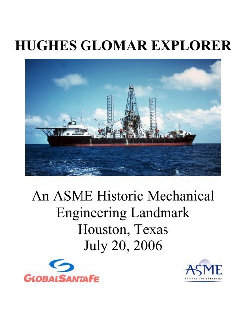
<strong>HUGHES</strong> <strong>GLOMAR</strong> <strong>EXPLORER</strong><br />
An ASME <strong>Historic</strong> Mechanical<br />
Engineering Landmark<br />
Houston, Texas<br />
July 20, 2006
Introduction<br />
The success of the Hughes Glomar Explorer proves that the impossible is, indeed, possible when talented engineers with<br />
the courage to take prudent risks are provided an incentive to stretch the state-of-the-art. The objective of the Hughes<br />
Glomar Explorer mission, retrieve a 2,000-ton (1,814-tonne) asymmetrical object from a water depth of 17,000 feet<br />
(5,182 meters), required a design incorporating unique solutions which were well beyond the state-of-the-art in numerous<br />
engineering and scientific disciplines, particularly mechanical engineering. For this reason the Hughes Glomar Explorer,<br />
as a complete deep-sea recovery system, has been designated an ASME <strong>Historic</strong> Mechanical Engineering Landmark.<br />
Grasping and raising a 2,000-ton (1,814-tonne) object in 17,000-feet (5,182-meters) of water in the central Pacific Ocean<br />
was a truly historic challenge requiring a recovery system of unprecedented size and scope. Major innovations and<br />
advances in mechanical engineering specifically required in the design of the Hughes Glomar Explorer include:<br />
1. A large center well opening in the hull and a means of sealing it off so that the objective could be examined in dry<br />
conditions<br />
2. A hydraulic lift system capable of hoisting a large, heavy load<br />
3. A tapered heavy lift pipe string, including tool joints, designed, constructed and proof tested to exceptionally<br />
demanding standards<br />
4. A “claw” with mechanically articulated fingers which used surface supplied sea water as a hydraulic fluid<br />
5. A motion compensated and gimbaled work platform system that effectively isolated the suspended load from the roll,<br />
pitch and heave motions of the ship<br />
6. A “docking leg” system which supported the weight and controlled the motion of the “claw” and load during the<br />
transition from dynamic open water conditions to the shelter of the ship’s center well<br />
Much of the specialized equipment employed on the Hughes Glomar Explorer was conceptually derived from standard<br />
drilling industry practice. The innovative, pragmatic application and adaptation of these concepts to meet the mission’s<br />
specific needs, however, is a testament to sound, creative mechanical engineering practice. The engineering design and<br />
manufacturing capabilities resulting from this project are used today by the deepwater offshore petroleum industry,<br />
particularly the use of electrical power to control sub-sea equipment.<br />
The Hughes Glomar Explorer and all of its subsystems, except the “claw”, were mothballed at the U.S. Navy fleet reserve<br />
center at Suisin Bay, California in 1975. The “claw’ was returned to Lockheed Ocean Systems in Redwood City,<br />
California and its disposition is unknown, but reportedly it has been scrapped. In 1979 the ship was re-activated, and,<br />
ironically, contracted to recover manganese nodules in anticipation of a commercial ocean mining venture. When the<br />
venture didn’t materialize the ship was re-mothballed in 1980. In 1996 GlobalSantaFe Corporation, a major U.S. drilling<br />
contractor leased the Hughes Glomar Explorer and converted it into a deep water drillship, re-named it the GSF Explorer,<br />
and currently operates it worldwide. Unfortunately, the conversion resulted in the removal and disposal of the unique<br />
equipment designed specifically for the deep water recovery mission.<br />
The Mission: The Jennifer Project<br />
In April 1968 the Soviet Golf-II class submarine K-129 sank in the Pacific Ocean near Hawaii. After an exhaustive but<br />
unsuccessful months-long search by Soviet vessels, it was clear that only the U.S. knew its whereabouts. The U.S.<br />
government contacted Global Marine Inc. in early 1970 regarding the feasibility of salvaging the vessel. In August 1970 a<br />
subsidiary of Global Marine Inc. submitted a proposal for construction and management of a recovery system and was<br />
subsequently designated the prime contractor, system integrator, and operations manager for the entire program. Sun<br />
Shipbuilding and Drydock Co. was selected in April 1971 to construct the Hughes Glomar Explorer portion of the<br />
recovery system. Major contracts were also awarded to Lockheed Ocean Systems Division for development and<br />
construction of the “claw” and to Hughes Tool Co. for development and fabrication of the heavy lift pipe. The hull of the<br />
partially outfitted Hughes Glomar Explorer was launched in November 1972. The ship was completed in July 1973 (at a<br />
cost of over $200 million) then mobilized via Cape Horn to the U.S. West coast, arriving in September 1973. After<br />
loading the 17,000-feet (5,182-meters) of heavy lift pipe and mating the “claw”, integrated sea trials were conducted off<br />
the California coast. In May 1974 the Hughes Glomar Explorer was declared ready for the mission and departed for<br />
location. The salvage mission commenced in July 1974 and was completed just five weeks later.
The Cover Story: The Deep Ocean Mining Project<br />
Oceanographers have long known that areas of the Pacific sea floor at depths from 14,000 to 17,000 feet (4,267 to 5,182<br />
meters) are carpeted with manganese nodules. Taking advantage of this phenomenon, the U.S. government approached<br />
Howard Hughes’ Summa Corporation about using its Deep Ocean Mining Project’s search for nodules as the reason for<br />
building the Hughes Glomar Explorer. The mission and the cover story remain shrouded in mystery to this day due to<br />
their national security implications. There is, however, no secret surrounding what is described herein regarding the<br />
specifications of the vessel and the great engineering challenges and unique solutions that are contained in her design and<br />
construction.<br />
The Ship: The Hughes Glomar Explorer<br />
The Hughes Glomar Explorer was designed and built as a self-contained, integrated mechanical system consisting of three<br />
major elements: the vessel Hughes Glomar Explorer, the heavy-lift pipe string, and the sub-sea grapple or “claw”. The<br />
specific engineering works considered most unique and representative of advances in mechanical engineering design are<br />
as follows:<br />
1. Gimbaled platform which isolates the suspended load from the ship’s dynamic pitch and roll. A gimbal is a<br />
pivoted ring, mounted at right angles to one or two other rings, to ensure that something, such as a ship’s<br />
compass, always remains horizontal.<br />
2. Hydraulic/pneumatic heave compensation system which prevents the ship’s heave motion from dynamically<br />
exciting the suspended load<br />
3. Hydraulic heavy-lift system to raise and lower the underwater machinery via the pipe string and attachments<br />
4. Heavy-lift pipe string<br />
5. Shipboard heavy-lift pipe handling system<br />
6. Vessel center well and sealing system<br />
7. Docking system that enabled the underwater machinery to be mated with the ship while in a dynamic seaway<br />
8. Underwater work platform or “claw”<br />
9. Sea Water Hydraulics and Umbilical Cables<br />
10. Submersible Barge.<br />
The following sections provide detailed descriptions of the ten major systems listed above.<br />
1. Gimbaled Platform<br />
The gimbaled platform provides a passively stable support structure for the heavy-lift system from which the “claw” and<br />
load are suspended during operations. This structure consists of outer and inner gimbaled elements that eliminate bending<br />
stresses in the pipe string as the ship rolls and pitches in a seaway. The 40 x 40-foot (12.2 x 12.2-meter) outer gimbal ring<br />
is a box weldment fabricated from high strength steel which is vertically supported by 48-inch (122-centimeter) diameter<br />
forged, hollow shafts attached to yokes mounted on the top of the heave compensator rams. The shafts turn through triple<br />
race anti-friction bearings mounted in the fore and aft faces of the outer gimbal, thus providing the roll axis of the<br />
platform. The inner gimbal element is an “H” shaped weldment which is connected to the outer gimbal element by two<br />
48-inch (122-centimeter) diameter pins extending from its sides through similar bearings mounted in the port and<br />
starboard faces of the outer gimbal element, thus providing the pitch axis of the platform.
The four gimbal bearings, each with a capacity of 5,000 tons (4,535 tonnes), are unique in size and design. The bearings<br />
consist of three races enclosing two sets of rollers. The 48-inch (122-centimeter) bore inner race accepts the gimbal’s<br />
structural pins. The outer race has an 8-foot (2.4-<br />
meter) outside diameter. An inner, double set of<br />
straight rollers and an outer double set of barrel<br />
rollers are separated by a middle race. The middle<br />
race is continuously rotated by an electric motor,<br />
and run at a speed sufficient to prevent any of the<br />
rollers from actually changing direction as the ship<br />
rolls and pitches in a seaway. The bearings are selfaligning<br />
to allow for structural deflections and<br />
construction tolerances.<br />
The inner gimbal, which is independent of ship roll,<br />
pitch, and heave motions, is the heart of the stable<br />
platform concept. The gimbaled platform is capable<br />
of accommodating ship motions of +/- 8.5 degree<br />
roll, +/- 5 degree pitch and 15-feet (4.6-meters) of<br />
heave. The upper pair of heavy-lift cylinders is<br />
mounted directly on top of the inner gimbal. The<br />
20-foot (6.1-meter) high rig floor substructure is also GIMBAL PLATFORM BEING LOWERED<br />
attached to the top of the inner gimbal and serves as DURING INSTALLATION<br />
the upper working deck for pipe handling operations.<br />
The lower pair of heavy-lift cylinders is welded to the underside of the inner gimbal. A strengthened foundation with a<br />
seating surface for a pipe tool joint is also provided at this level. This “parking brake” is used to take the load off the<br />
heavy-lift system for maintenance or during severe weather. A 10,000-ton (9,070-tonne) thrust bearing installed below the<br />
inner gimbal is used to rotate and align the axis of the “claw” with the docking legs during docking.<br />
2. Heave Compensator System<br />
The heave compensator system is installed between the gimbaled platform and the ship’s structure. Its function is to<br />
minimize the dynamic axial stresses in the<br />
heavy-lift pipe string by allowing a controlled<br />
amount of relative motion between the gimbaled<br />
platform and the ship. The system’s spring rate<br />
(rate at which it responds to movement of the<br />
ship) can be adjusted to the specific dynamic<br />
environment resulting from wave forces, ship<br />
motion characteristics, platform motion,<br />
suspended loads, and length of the pipe string.<br />
The passive, hydraulic/pneumatic heave<br />
compensation system consists of two 65-inch<br />
diameter upward stroking rams mounted on the<br />
centerline of the ship on two large structures that<br />
span the center-well. The outer gimbaled<br />
platform is supported on top of the two rams.<br />
The design range for vertical motion is +/- 7.5<br />
feet (2.3 meters), and the system’s maximum<br />
load capacity is 10,000 tons (9,070 tonnes). The<br />
system air pressure is adjusted to match the load<br />
on the gimbaled platform at mid-stroke, while<br />
the number of air bottles placed on line controls<br />
the effective spring rate of the system.<br />
HEAVE COMPENSATOR SYSTEM
A 36-inch (91-centimeter) rubber and steel flex joint installed on the bottom of each ram cylinder isolates the rams from<br />
structural deflections and construction tolerances. The rams are fitted with a patented internal hydraulic “snubber” to<br />
protect the system in the event of a rapid over-travel during their stroke.<br />
3. Hydraulic Heavy-lift System<br />
The 7,000-ton (6,350-tonne) capacity hoisting<br />
system is the nucleus of the Hughes Glomar<br />
Explorer’s ability to lower and raise heavy loads<br />
to and from the seafloor. The lift system utilizes<br />
two pairs of 60-inch (152-centimeter) internal<br />
diameter hydraulic cylinders with a 15-foot (4.6-<br />
meter) nominal stroke mounted on the inner<br />
gimbaled platform. The rod ends of the cylinders<br />
point downward and each pair is connected with<br />
heavy steel yokes which support the pipe string at<br />
its tool joints which are spaced every 30 feet (9.1<br />
meters). The cylinders are arranged with one pair<br />
45-feet (13.2-meters) above the other and rotated<br />
90 degrees so that the upper yoke can move<br />
between the cylinders of the lower pair. During SECTION THROUGH HEAVY LIFT<br />
operation the upper and lower cylinder pairs (LOOKING FORE/AFT)<br />
alternately pick up and release the load in a continuous,<br />
automated hand-to-hand sequence. The system is designed for a constant lifting/lowering speed of 18-feet (5.5-meters) per<br />
minute, although actual operations were carried out at a lesser rate.<br />
The structural yokes connecting each pair of cylinder rods have a clear opening through their centers that can pass the<br />
heavy-lift pipe tool joint. Each yoke has two sliding mechanisms that hydraulically move into place under the tool joint’s<br />
flat shoulder to assume the 7,000-ton (6,350-tonne) load. The upper yoke also contains a device that can apply 500,000-ftlbs<br />
(677,900-newton-meters) of make up torque to the tool joints and exert up to one million-ft-lbs (1,356,000-newtonmeters)<br />
of breakout torque if needed.<br />
4. Heavy-lift Pipe String<br />
The 17,000-foot (5,182-meter) forged steel heavy-lift pipe string is comprised of 570 joints, each one being 30-feet (9.1meters)<br />
long. The pipe material and the manufacturing process are derived from the military specification for large bore<br />
naval and shore battery gun barrels. The pipe sections are hammer forged with large upsets on each end to accommodate<br />
the machining of integral tool joints.<br />
Physical scale model tests of various thread configurations resulted in the selection of a modified buttress thread with a<br />
steep taper. All finished pipe joints were proof tested to approximately 88 percent of the material’s minimum yield<br />
strength in a specially constructed machine capable of 24,000,000 pounds (10,884,000-kilos) of tensile pull.<br />
To minimize the wet weight of the pipe string yet meet the strength requirements, six pipe body outer diameters are used<br />
ranging in size from 15.5 to 12.75 inches (39.4 to 32.4 centimeters). Although all pipe sections have a constant 6-inch<br />
(15.2- centimeter) bore, there are three tool joint diameters ranging from 28 to 25.5 inches (71.1 to 64.8 centimeters).<br />
Each box end tool joint has a flat support shoulder that rests on the heavy-lift yokes during operation. Both the pin and<br />
box tool joints have nine machined slots around their diameter to accommodate the make-up/break-out torquing device on<br />
the upper lifting yoke. Normally, the pipe is stored, handled, made up, and broken down from the string in 60-foot (18.3-<br />
meter) long double sections, ranging in weight from 12 to 20 tons (10.9 to 18.1 tonnes). The finished, dry weight of the<br />
pipe string is approximately 4,000 tons (3,628 tonnes) and the pay-load capacity at the end of the fully deployed 17,000-<br />
foot (5,182-meter) string is approximately 4,250 tons (3,855 tonnes).
HEAVY-LIFT PIPE TOOL JOINT MANUFACTURED BY <strong>HUGHES</strong> TOOL COMPANY<br />
5. Heavy-lift Pipe Handling System<br />
The 18-foot (5.5-meter) per minute raising/lowering speed of the heavy lift system dictates that a 60-foot (18.3-meter)<br />
long pipe section be inserted (or removed) every 3.3 minutes. The handling procedure includes retrieving a 12 to 20-ton<br />
(10.9 to 18.1-tonne) pipe section from a horizontal position in<br />
the storage hold below deck, transporting it to the rig floor<br />
located over 100-feet (30.5-meters) above the deck, raising it<br />
to a vertical position, and stabbing it into an upward facing<br />
box connection which is continuously being lowered by the<br />
heavy-lift system. This operation must be carried out while the<br />
ship is rolling and pitching in a seaway.<br />
The Pipe Handling System is comprised of six distinct<br />
machines:<br />
Two manually operated bridge cranes in the storage hold<br />
retrieve a 60-foot (18.3-meter) section of pipe from a bin, lift it<br />
to the top of the hold, and transport it transversely to a<br />
centerline elevator. Telescoping guide tubes are fitted around<br />
the hoisting blocks so that the two pipe grapples are made<br />
rigid, even at their maximum 35-foot (10.7-meter) vertical<br />
extension. The centerline elevator utilizes two hydraulic<br />
cylinders to raise the pipe through a hatch in the main deck<br />
into position for pick up by the transfer crane.<br />
The transfer crane has a grapple device at the end of its boom<br />
which grasps the pipe around its center tool joint, picks it up<br />
from the elevator, and transports it to starboard where<br />
it places it on the pipe transfer cart. PIPE HANDLING SYSTEM<br />
Despite the motion of the ship the pipe is always under rigid hydraulic control.<br />
The pipe transfer cart, which rides on rails atop the transfer boom, carries the pipe from the deck to the<br />
gimbaled rig floor. The transfer cart is pulled along the boom by a hydraulically driven winch.
When the pipe section arrives at the rig floor its top (box) end is directly in line with the center of the lift system<br />
and between two, upward curving, “banana-shaped” guide rails. The guide rails hold the lifting and stabbing<br />
guide which positions the automatic roughneck. The elevator/sub-spinner, which is attached to the traveling<br />
block bails, is clamped around the pipe. A stabbing guide mechanism firmly controls the lower end of the pipe<br />
as the upper end is raised into the derrick by the elevator/sub-spinner. The automatic roughneck controls the<br />
lower end of the pipe and guides it into vertical alignment with the heavy-lift pipe already in the system. The<br />
elevator/sub-spinner spins the pipe as it is lowered to engage the threads of the downward moving tool joint box<br />
and then applies approximately 50,000-ft-lbs (67,790-newton-meters) of torque to the tool joint.<br />
6. Docking Well<br />
The size of the object to be raised determined that the ship must have a dry center-well 199-feet (60.7-meters) long and<br />
74- feet (22.6-meters) wide with a 65-foot (19.8-meter) clear vertical height. The center well is closed from the sea by two<br />
gates that roll longitudinally, one forward and one aft, in gate guide rails built onto the bottom of the ship’s hull. The two<br />
gates are 9-foot (2.7-meter) deep barge-like pontoons with wheels along their sides and a two-compound rubber sealing<br />
gasket on the topside where the gates overlap the ship’s hull. Regulating the air volume in each gate’s free flooding (open<br />
bottom) compartments allows their buoyancy to be controlled. When the gates are closed and made positively buoyant,<br />
the perimeter gasket seals against the ship’s hull and high volume pumps remove water from the center-well. When the<br />
hydrostatic pressure differential between outside and inside reaches a few feet the gates are adequately sealed and held in<br />
position.<br />
To open the gates, the well is flooded with seawater to equalize the pressure and the floodable gate compartments are<br />
flooded. The gates become negatively buoyant and sink several inches until their steel wheels contact the gate guide rails.<br />
The gates can then be powered open (or closed) by a rack and pinion arrangement. Once in the fully open position the gate<br />
ballast tanks are blown down, become positively buoyant, and hold their position against the hull.<br />
7. Docking System<br />
The docking system is an innovative solution to one of the most vexing problems facing the mission – how to stabilize a<br />
4,000-ton (3,628-tonne) load which is suspended from a single point in a dynamic seaway environment and then hoist it<br />
into the narrow confines of the ship’s center-well. Furthermore, when the load is transferred to or from the pipe string and<br />
heavy lift system, the “claw” must be supported by some other structure. The solution was to provide two semi-rigid<br />
structural arms or “docking legs” that could support the weight and also reach below the ship’s hull to guide the “claw”<br />
and payload as it is hoisted into the center-well.<br />
The docking legs are modified sections of jackup drilling rig legs with continuous racks on two of the three vertical<br />
members. The electric driven, rack and pinion elevating system and integral guide structure are also standard modular<br />
design. The upper portion of the leg is made up of simple triangular trusses. The flat lower section incorporates a<br />
“keyhole” that engages a 48-inch (122-centimeter) diameter “docking pin” located on each end of the “claw”. A second<br />
structural pin on the “claw”, located about 10 feet (3 meters) directly below the main support pin, engages a second slot<br />
on the leg and serves to resist the torque from asymmetrical loads on the “claw”. Once seated in the supporting keyhole,<br />
the “claw” can be shifted laterally about 8 feet (2.4 meters) to accommodate the asymmetrical dimensions of the load<br />
being raised into the ship.<br />
The legs are raised and lowered by standard jack-up electric elevating units. When docking/undocking, two hydraulic tilt<br />
cylinders on each support truss are actuated to allow the legs to tilt up to 7 degrees fore and aft. The hydraulic system<br />
incorporates a pneumatic/hydraulic circuit that allows for the gradual dampening of relative surge and pitch motions as the<br />
ship and the “claw” respond differently to the wave forces. The submerged claw acts as a massive damper, significantly<br />
reducing the ship’s roll motion. Once the bridle connecting the “claw” to the heavy-lift pipe is attached and the weight<br />
transferred to the heavy-lift system, the load is raised from the leg’s keyhole slots, the legs are fully tilted to clear the pins,<br />
and the claw is lowered to the sea bed using the hydraulic heavy-lift system.
DOCKING LEG SYSTEM DOCKING LEG SYSTEM<br />
8. Underwater Work Platform or “Claw”<br />
The structural spine of the Underwater Work Platform, or “claw”, is a deep box girder which, when fully outfitted, weighs<br />
approximately 2,000 tons (1,814 tones). It is supported by a three-point, hinged bridle when suspended from the pipe<br />
string. During docking/undocking operations, 48-inch (122-centimeter) diameter “docking pins” support the “claw” at the<br />
ends. Multiple hydraulically operated, articulated fingers are attached to the underside of the box girder. The welded beam<br />
fingers, some of which are over 30 feet (9.1 meters) long with multiple articulated joints, are fabricated from high strength<br />
steel plate, 1 to 2 inches (2.53 to 5.08 centimeters) thick. Large bore hydraulic cylinders, using seawater as a hydraulic<br />
fluid, actuate the fingers. Four low pressure, vertically telescoping legs are installed at the corners. After the fingers are<br />
closed around the object, these legs are actuated with seawater to exert an additional 2,000-ton (1,814-tonne) force against<br />
the seabed to overcome the soil’s embedment restraint on the object.<br />
Eight hydraulically driven, fixed azimuth propeller thrusters are located on top of and at the extremities of the “claw”. A<br />
hydraulic motor, specially modified with dry film lubricant to operate on seawater pressure, drives the 5-foot (1.5-meter)<br />
diameter propellers. During near bottom operations a sub-sea acoustic positioning system commands the thrusters to<br />
position the “claw” over the desired spot on the seafloor, irrespective of the position of the ship three miles (4.8<br />
kilometers) above. The ship’s positioning system then senses the bias in the “claw” positioning system and commands the<br />
ship’s thrusters to position the ship directly over the “claw”.
9. Sea Water Hydraulics and Umbilical Cables<br />
SUBSEA EQUIPMENT LOWERED TO RELEASE DEPTH<br />
Pressurized seawater is supplied to the “claw” via the 6-inch (15.2-centimeter) bore of the heavy-lift pipe string. The<br />
pressure is generated from the ship’s two 1,600-HP oilfield mud pumps. Electric power and control wiring is provided<br />
from the surface to the “claw” via two 18,000-foot (5.5-kilometer) waterproof cables. Each cable has the capacity to<br />
transmit 75 kW of power.<br />
10. Submersible Barge<br />
The “claw” was transported fully outfitted from the shipyard to the Hughes Glomar Explorer on a large submersible<br />
barge, the HMB-1 (see picture below). This barge has a retractable cover to conceal its contents. The barge was<br />
submerged to the shallow seabed prior to the ship being positioned over it so that the claw could be lifted into the centerwell<br />
by the docking legs. The barge has since been used to transport the “Sea Shadow” stealth ship for sea trials.
Participants<br />
Due to this project’s large scope and complexity it is impossible, and perhaps unfair, to identify individual engineers as<br />
responsible for the many integrated elements of the Hughes Glomar Explorer program. Suffice to say it was literally a<br />
cast of hundreds, primarily mechanical engineers, many of them ASME members, who contributed their own expertise. It<br />
is appropriate, however, to name the major corporations that participated and their area of involvement.<br />
Global Marine Development Inc. – prime contractor, systems integrator, operations manager, vessel designer and<br />
marine operator.<br />
Lockheed Ocean Systems Division – development, construction, and operation of the sub-sea machinery including the<br />
submersible barge.<br />
Hughes Tool Company – design, development, fabrication, and testing of the heavy-lift pipe string. Summa Corporation,<br />
a subsidiary of Hughes Tool Company, was the surrogate “client” who provided the cover story of a commercial deep-sea<br />
manganese mining venture.<br />
Western Gear Corporation, Heavy Machinery Division – development, construction, testing, and at-sea operation of<br />
the heavy lift and heave compensating systems.<br />
Honeywell Ocean Systems – development, construction, installation, and operation of long and short base line acoustic<br />
positioning systems.<br />
Sun Shipbuilding & Drydock Corporation – detailed design and construction of Hughes Glomar Explorer vessel.<br />
American Bureau of Shipping – commercial agency responsible for certifying the ship and its systems meet the<br />
applicable rules for classification as Maltese Cross A1 – E.<br />
General Electric Corporation – development and provision of the vessel’s electrical components including a first-of-itskind<br />
4160 volt distribution system and the first marine application of SCR variable speed drives.<br />
Battelle Memorial Institute – proof testing of each section of the heavy-lift pipe with 12,000 ton (10,884 tonnes) tensile<br />
pull machine<br />
Marathon-LeTourneau – fabrication of docking legs and jacking motors<br />
The significant involvement of many other companies not listed above who contributed to the success of this project is<br />
recognized.<br />
The following references are provided for visitors who are interested in reading more about the Hughes Glomar Explorer<br />
and the Jennifer Project. GlobalSantaFe, however, assumes no responsibility for the accuracy of any of the material.<br />
Annonymous. Glomar Explorer’s Many Technical Innovations. 1976. Ocean Industry. December 1976: 67-73.<br />
Burleson, Clyde W. The Jennifer Project. 1977. College Station: Texas A&M University Press.<br />
Craven, John P. 2001. The Silent War. New York: Simon and Schuster.<br />
Dunham, Roger C. 1996. Spy Sub. Annapolis: <strong>Naval</strong> Institute Press.<br />
McNary, J.F., Person, A., and Ozudogru, Y.H. 1977. A 7,500-Ton-Capacity, Shipboard, Completely Gimbaled<br />
and Heave-Compensated Platform. Journal of Petroleum Technology April 1977: 439-448.<br />
Sewell, Kenneth. 2005. Red Star Rogue. New York: Simon and Schuster.<br />
Sontag, Sherry and Drew, Christopher. 1998. Blind Man’s Bluff. New York: Public Affairs.<br />
Varner, Roy and Collier, Wayne. 1978. A Matter of Risk. New York: Random House, Inc.
We wish to recognize Global Marine personnel who contributed to the design, construction, operation<br />
and support of the Hughes Glomar Explorer during the deep-sea salvage project. Unfortunately, time has<br />
taken its toll on our personnel records. While every effort was made to compile a complete list, we are<br />
certain there are individuals who were inadvertently overlooked, and for that we apologize.<br />
Terri Adamic<br />
Grant Allen<br />
Richard Allen<br />
Charles Alonjie<br />
Maynard Amundson<br />
Robert Arnall<br />
Carl Atherton<br />
John Bachino<br />
Jay Bamber<br />
Warren Bebow<br />
Maurice Belleville<br />
Julius Berczik<br />
Cindy Berry<br />
Alfred Bilang<br />
Barry Bird<br />
James Black<br />
Vance Bolding<br />
Don Borchardt<br />
Stephen Blanchard<br />
Leon Blurton<br />
Philip Blurton<br />
Charles Bozarth<br />
Sebe Bracey<br />
Harold Bradley<br />
Sonja Bridgeforth<br />
Cindy Brinkley<br />
Clarence Brown<br />
Donald Bull<br />
John Burford<br />
Charles Canby<br />
Chuck Cannon<br />
Carl Carlisle<br />
John Carpenter<br />
Philip Carpenter<br />
Richard Casse<br />
Dale Cheeseman<br />
Malcolm Clark<br />
Glenn Clemens<br />
Micky Cohen<br />
Eugene Coke<br />
James Cole<br />
Renee Comeau<br />
Danny Constantino<br />
James Cooper<br />
Robert Cooper<br />
Curtis Crooke<br />
Laura Crouchet<br />
Henry Cuffle<br />
Jim Culp<br />
Malcolm Currie<br />
Bud Cusick<br />
James Cusick<br />
Tullio D’Angelo<br />
Vernon Davenport<br />
Jim Dean<br />
Don deBourguignon<br />
Bob Demichelle<br />
Joe Dickey<br />
Jack Delaney<br />
Tom Dixon<br />
Donald Douglas<br />
James Drahos<br />
Bill Druitt<br />
Amy Dubick<br />
Larry Eckhardt<br />
Nick Ellis<br />
Bruce Erickson<br />
John Evans<br />
Barbara Evenson<br />
Robert Falconer<br />
Arleen Feltman<br />
Jan Ford<br />
Harry Fraley<br />
Daniel Fuller<br />
Ralph Garside<br />
Joe Gates<br />
King Gibson<br />
Gene Gilmore<br />
Guy Glass<br />
Jerry Goodner<br />
John Grahm<br />
Reginald Greatbanks<br />
Tom Gresham<br />
Bedford Griggs<br />
Joseph Guzzardi<br />
Gary Haddon<br />
Ray Haese<br />
Max Halebsky<br />
Taylor Hancock<br />
Kirk Hankins<br />
Phil Hardwick<br />
Kevin Hart<br />
Mike Hartt<br />
Bonnie Hess<br />
John Hicks<br />
James Higman<br />
Roger Hnat<br />
Robert Hogdon<br />
John Hollett<br />
Garvin Holt<br />
Ronald Howell<br />
Walter Hull<br />
C.W. Hurd<br />
John Hutchins<br />
Howard Imamura<br />
Joseph Imondi<br />
Paul Ito<br />
Michael Jefferis<br />
Preston Jobe<br />
Charlie Johnson<br />
Colleen Johnson<br />
Steve Johnson<br />
Walter Jones<br />
Howard Jones<br />
Skeet Jones<br />
Elmer Kaiser<br />
Micky Kahn<br />
John Kane<br />
Steve Kemp<br />
Dayton Knorr<br />
Leslie Koerner<br />
Thomas Koonings<br />
Larry Krueger<br />
Manfred Krutain<br />
John Kucera<br />
Robert Labarthe
Donna LaPorte<br />
Daniel Landsverk<br />
Barbara Lewis<br />
Ben Luttrell<br />
Lewis Madara<br />
Ed Madden<br />
Vincent Martelli<br />
Cornelius Martin<br />
Gil Mason<br />
Sharon McCain<br />
John McClure<br />
George McKee<br />
Russel McKinley<br />
Jim McNary<br />
Mike Meade<br />
Richard Meadows<br />
Richard Mee<br />
Cliff Melberg<br />
Eddie Merril<br />
Randy Michaelson<br />
Jim Miles<br />
Gaylan Million<br />
Joe Minton<br />
Cotton Moffett<br />
Scott Monson<br />
Stan Moon<br />
Therese Murphy<br />
Larry Myers<br />
Charles Newton<br />
Fred Newton<br />
Bobby Nichols<br />
Donald Oulette<br />
Ed Outen<br />
John Owens<br />
Yilmaz Ozadugru<br />
John Parker<br />
John Parsons<br />
David Pasho<br />
Jal Patell<br />
Wayne Pendleton<br />
Abe Person<br />
Luis Pettus<br />
James Phillips<br />
Thomas Phillips Jr.<br />
Eugene Prino<br />
Charles Prose<br />
Harold Ramsden<br />
Larry Randall<br />
Per Randrup<br />
Robert Reed<br />
Mike Reimers<br />
Fred Remington<br />
Clyde Reynolds<br />
Jeffery Robbins<br />
Chuck Robidart<br />
Adan Rodriguez<br />
George Rodts<br />
Jim Rogers<br />
John Salancy<br />
Jay Sanders<br />
Bill Schaper<br />
Steve Schneider<br />
Frederick Schubert<br />
William Schutt<br />
Lyle Seerey<br />
Ben Shimada<br />
Andy Shrock<br />
Charles Simons<br />
Douglas Simpson<br />
Richard Singer<br />
Richard Sink<br />
Harold Sinyard<br />
Bill Skipton<br />
Joe Slevin<br />
Archie Smith<br />
Sybil Smith<br />
Edward Smith<br />
Weston Smith<br />
Oran Spencer<br />
Rae Spencer<br />
Knut Stang<br />
Maurice Star<br />
Edward Stevens<br />
William Stevens<br />
A. Stupp<br />
Jeanna Summers<br />
Bill Terry<br />
Tommy Thompson<br />
Russ Thornberg<br />
Cheryl Valanes<br />
Brad Van Hofwegen<br />
John Valentine<br />
Earl Vanderport<br />
Edward Voelker<br />
Jimmy Walker<br />
Bob Wallerstadt<br />
John Walsh<br />
Dave Walton<br />
Roger Warren<br />
Linda Webber<br />
Steven Welch<br />
Sherman Wetmore<br />
Bob Wheeler<br />
Don White<br />
Bill Wilbur<br />
Walt Willard<br />
Steve Williams<br />
Tom Williams<br />
Howard Winkle<br />
Richard Wolf<br />
Leland Zanteson<br />
Gail Zeleny<br />
Ed Zick<br />
Joyce Ziegler
The History and Heritage Program of ASME<br />
The ASME History and heritage Program began in September 1971. To implement and achieve its goals,<br />
ASME formed a History and Heritage Committee, comprised of mechanical engineers, historians of<br />
technology, and the Curator Emeritus of Mechanical and Civil Engineering at the Smithsonian Institution.<br />
The committee provides a public service by examining, noting, recording, and acknowledging mechanical<br />
engineering achievements of particular significance. The History and Heritage Committee is part of the<br />
ASME Council on Public Affairs and Board on Public Information. For further information, please contact<br />
Public Information, the American Society of Mechanical Engineers, Three Park Avenue, New York, NY<br />
10016-5990, 212-591-7740, fax 212-591-8676.<br />
An ASME landmark represents a progressive step in the evolution of mechanical engineering. Site<br />
designations note an event or development of clear historical importance to mechanical engineers.<br />
Collections mark the contributions of several objects with special significance to the historical development<br />
of mechanical engineering.<br />
The ASME Mechanical Engineering Recognition Program illuminates our technological heritage and<br />
serves to encourage the preservation of the physical remains of historically important works. It provides an<br />
annotated roster for engineers, students, educators, historians, and travelers, and helps establish persistent<br />
reminders of where we have been and where we are going along the divergent paths of discovery.<br />
ASME International Board of Governors<br />
Terry E. Shoup, President Terry Shoup, President<br />
Virgil Carter, Executive Director Gene E. Feigel, Past President<br />
Tom Loughlin, Deputy Executive Director Virgil Carter, Executive Director<br />
Elizabeth Barna, Executive Office William T. Cousins, Term 2004-2007<br />
Dirk F. Dauw, Term 2004-2007<br />
International Petroleum Technology Robert J. Simoneau, Term 2004-2007<br />
Institute Board James W. Coaker, Term 2005-2008<br />
Bobby Grimes, Chair Alma U. Martinez Fallon, Term 2005-2008<br />
Joe Fowler, Board Member Ozden O. Ochoa, Term 2005-2008<br />
Terry Lechinger, Board Member Victoria A. Rockwell 2006-2009<br />
Denby Morrison, Board Member Chittaranjan Sahay 2006-2009<br />
Edmund Seiders, Board Member Robert T. Simmons 2006-2009<br />
George Wolfe, Board Member<br />
Ken Paulson, Board Member<br />
International Petroleum Technology<br />
Institute Staff and Officers<br />
Manny Mones, Director<br />
Lisa Elliott, Meetings Manager<br />
Amrah Goebel, Administrative Assistant, Meetings and Member Affairs<br />
Kim Miceli, Administrative Assistant, Meetings and New Media<br />
Petroleum Division Executive Committee ASME South Texas Section<br />
Bill Eustes, Chairman Ryan Schmidt, Chairman<br />
Phil Collins John Bradford, Vice Chairman<br />
Skipper Strong Greg Berry, Treasurer<br />
Charlie Burton Robert Bradshaw, Secretary<br />
Don Wells Richard Boswell, P.E., History and<br />
Kenneth Bayne Heritage Chairman<br />
Tom Kelly Glenn MacDonald, P.E., History and<br />
Heritage Vice-Chairman<br />
ASME History and Heritage Committee<br />
R. Michael Hunt, P.E., History and Heritage Chair<br />
Robert M. Vogel, Secretary<br />
John K. Brown<br />
William DeFotis<br />
Paul J. Torpey, Past President<br />
Diane Kaylor<br />
Maria Stennos, Staff Liaison
Acknowledgements<br />
ASME thanks all those who have contributed to the designation of the Hughes Glomar Explorer. Special<br />
thanks to Keith Thayer, past president of ASME 1997-1998, for nominating this landmark and Sherman<br />
Wetmore and Bruce Watson and the Staff of GlobalSantaFe.
PLAQUE<br />
<strong>HUGHES</strong> <strong>GLOMAR</strong> <strong>EXPLORER</strong><br />
1972<br />
THE <strong>HUGHES</strong> <strong>GLOMAR</strong> <strong>EXPLORER</strong> WAS BUILT FOR A COVERT U.S.<br />
GOVERNMENT PROJECT THAT RETRIEVED PART OF A SUNKEN SOVIET<br />
SUBMARINE FROM THE PACIFIC OCEAN IN 1974. IT WAS BUILT AROUND<br />
AN INTEGRATED MECHANICAL SYSTEM DESIGNED FOR THE DAUNTING<br />
PURPOSE OF RAISING A 2,000-TON OBJECT 17,000 FEET FROM THE<br />
OCEAN FLOOR. KEYS TO ITS SUCCESS WERE AN INNOVATIVE CLAW<br />
MECHANISM, A GIMBALED MOUNT TO STABILIZE THE PIPE STRING AND<br />
A DYNAMIC POSITIONING SYSTEM THAT MAINTAINED THE VESSEL’S<br />
LOCATION THROUGHOUT THE RECOVERY OPERATION.<br />
CONVERTED FOR DEEPWATER DRILLING IN 1998, ITS STABILIZING AND<br />
POSITIONING CONCEPTS BECAME A MODEL FOR SUBSEQUENT<br />
DRILLING RIGS.<br />
AMERICAN SOCIETY OF MECHANICAL ENGINEERS 2006


