

HUGHES GLOMAR EXPLORER - Historic Naval Ships Visitors Guide
HUGHES GLOMAR EXPLORER - Historic Naval Ships Visitors Guide
HUGHES GLOMAR EXPLORER - Historic Naval Ships Visitors Guide

You also want an ePaper? Increase the reach of your titles
YUMPU automatically turns print PDFs into web optimized ePapers that Google loves.
The four gimbal bearings, each with a capacity of 5,000 tons (4,535 tonnes), are unique in size and design. The bearings<br />
consist of three races enclosing two sets of rollers. The 48-inch (122-centimeter) bore inner race accepts the gimbal’s<br />
structural pins. The outer race has an 8-foot (2.4-<br />
meter) outside diameter. An inner, double set of<br />
straight rollers and an outer double set of barrel<br />
rollers are separated by a middle race. The middle<br />
race is continuously rotated by an electric motor,<br />
and run at a speed sufficient to prevent any of the<br />
rollers from actually changing direction as the ship<br />
rolls and pitches in a seaway. The bearings are selfaligning<br />
to allow for structural deflections and<br />
construction tolerances.<br />
The inner gimbal, which is independent of ship roll,<br />
pitch, and heave motions, is the heart of the stable<br />
platform concept. The gimbaled platform is capable<br />
of accommodating ship motions of +/- 8.5 degree<br />
roll, +/- 5 degree pitch and 15-feet (4.6-meters) of<br />
heave. The upper pair of heavy-lift cylinders is<br />
mounted directly on top of the inner gimbal. The<br />
20-foot (6.1-meter) high rig floor substructure is also GIMBAL PLATFORM BEING LOWERED<br />
attached to the top of the inner gimbal and serves as DURING INSTALLATION<br />
the upper working deck for pipe handling operations.<br />
The lower pair of heavy-lift cylinders is welded to the underside of the inner gimbal. A strengthened foundation with a<br />
seating surface for a pipe tool joint is also provided at this level. This “parking brake” is used to take the load off the<br />
heavy-lift system for maintenance or during severe weather. A 10,000-ton (9,070-tonne) thrust bearing installed below the<br />
inner gimbal is used to rotate and align the axis of the “claw” with the docking legs during docking.<br />
2. Heave Compensator System<br />
The heave compensator system is installed between the gimbaled platform and the ship’s structure. Its function is to<br />
minimize the dynamic axial stresses in the<br />
heavy-lift pipe string by allowing a controlled<br />
amount of relative motion between the gimbaled<br />
platform and the ship. The system’s spring rate<br />
(rate at which it responds to movement of the<br />
ship) can be adjusted to the specific dynamic<br />
environment resulting from wave forces, ship<br />
motion characteristics, platform motion,<br />
suspended loads, and length of the pipe string.<br />
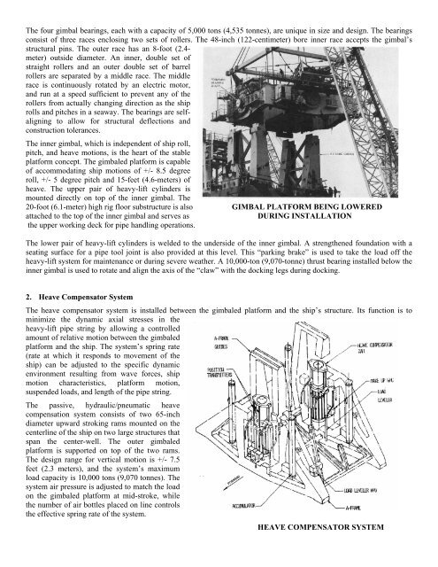
The passive, hydraulic/pneumatic heave<br />
compensation system consists of two 65-inch<br />
diameter upward stroking rams mounted on the<br />
centerline of the ship on two large structures that<br />
span the center-well. The outer gimbaled<br />
platform is supported on top of the two rams.<br />
The design range for vertical motion is +/- 7.5<br />
feet (2.3 meters), and the system’s maximum<br />
load capacity is 10,000 tons (9,070 tonnes). The<br />
system air pressure is adjusted to match the load<br />
on the gimbaled platform at mid-stroke, while<br />
the number of air bottles placed on line controls<br />
the effective spring rate of the system.<br />
HEAVE COMPENSATOR SYSTEM


